Advertisement
Quick Links
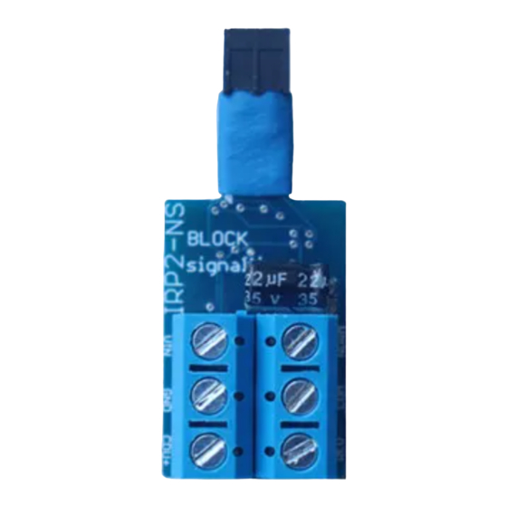
AUTOMATIC LED SIGNAL CONTROLLER ASP2-NS
(for COMMON-ANODE SIGNALS)
Controlling multi-aspect signals on model railways has never been easier
Detects trains passing signals using its in-built infra-red sensor
Fades leds in and out to simulate incandescent bulbs
Very simple to connect up to signals
No soldering required, all components are ready wired-up
No programming required (but you can adjust all settings if you wish)
For use with common-anode led signals (not signals that use bulbs)
Operates from 12V DC
Advertisement

Related Manuals for BLOCKsignalling ASP2-NS


Summary of Contents for BLOCKsignalling ASP2-NS
- Page 1 AUTOMATIC LED SIGNAL CONTROLLER ASP2-NS (for COMMON-ANODE SIGNALS) Controlling multi-aspect signals on model railways has never been easier Detects trains passing signals using its in-built infra-red sensor Fades leds in and out to simulate incandescent bulbs ...
- Page 2 Example Wiring for 2-aspect Common-Anode Signal GREEN Invisible Infra-Red Light Standard version: 16mm BLOCKsignalling ASP2-NS SIGNAL BLACK WIRE (LEDS +) POWER SUPPLY RED WIRE (RED LED -) GREEN WIRE (GREEN LED -) Notes: 1. The signal common positive wire shares a terminals with one of the power supply wires.
- Page 3 BLOCKsignalling www.blocksignalling.co.uk Connecting Up The module has six terminals. Negative feed from the DC supply. Positive feed from the 12V DC supply. It is also the connection for the signal common positive wire. This is the negative feed to the RED aspect...
- Page 4 BLOCKsignalling www.blocksignalling.co.uk Operation With the power switched on, the red led on the PCB should flicker rapidly and the signal should show clear (green). If a train now passes over the sensor, or you wave your hand close to the sensor, the signal will switch to danger (red).
- Page 5 Example Wiring for 2-aspect Common-Anode Signal GREEN Invisible Infra-Red Light Standard version: 16mm BLOCKsignalling ASP2-NS SIGNAL BLACK WIRE (LEDS +) POWER SUPPLY RED WIRE (RED LED -) GREEN WIRE (GREEN LED -) Notes: 1. The signal common positive wire shares a terminals with one of the power supply wires.
- Page 6 Example Wiring for 3-aspect Common-Anode Signal GREEN YELLOW Invisible Infra-Red Light Standard version: 16mm BLOCKsignalling ASP2-NS SIGNAL BLACK WIRE (LEDS +) POWER SUPPLY RED WIRE (RED LED -) YELLOW WIRE (YELLOW LED -) GREEN WIRE (GREEN LED -) Notes: 1. The signal common positive wire shares a terminals with one of the power supply wires.
- Page 7 BLOCKsignalling www.blocksignalling.co.uk Program 4 (4-Aspect Signalling) This program simulates the operation of a four aspect signal, which is normally showing green. The module searches for a train, and if one is detected in front of the sensor, the signal immediately switches to red.
- Page 8 BLOCKsignalling www.blocksignalling.co.uk Changing the Timing of each Phase The individual time for each of the phases can be adjusted to suit (as supplied they are set to 1 second each, which is ideal for initial testing). Once you are happy with the operation of the train detection, you will probably want to change these to more realistic values.
- Page 9 BLOCKsignalling www.blocksignalling.co.uk Other Programming Options There are a number of parameters which can be adjusted if you wish to alter the operation of the module. Release Time This is the time that the infra-red sensor must be continuously unobstructed for the module to confirm the train has passed.
- Page 10 BLOCKsignalling www.blocksignalling.co.uk Program Flow Diagram As mentioned above, there are a number of memory locations which can programmed with different values to change the operation of the module. Before starting, it is a good idea to write down the memory locations and the values you are going to set them to.
- Page 11 BLOCKsignalling www.blocksignalling.co.uk Any signals show in diagrams and photos are only to illustrate connections and are not included with the module. Page 11 of 13...
- Page 12 BLOCKsignalling www.blocksignalling.co.uk Troubleshooting When the power supply is connected and switched on, the red led on the module should light for 1 second, then flicker at a fast rate. This flickering indicates that the module is looking for a train in front of the sensor.
- Page 13 BLOCKsignalling www.blocksignalling.co.uk 5. If the signal aspects do not light as expected, wire each output in turn to the green output (with the other aspects not connected) to confirm that all the aspects of the signal work when separately connected to the green channel.
Need help?
Do you have a question about the ASP2-NS and is the answer not in the manual?
Questions and answers