Advertisement
Quick Links
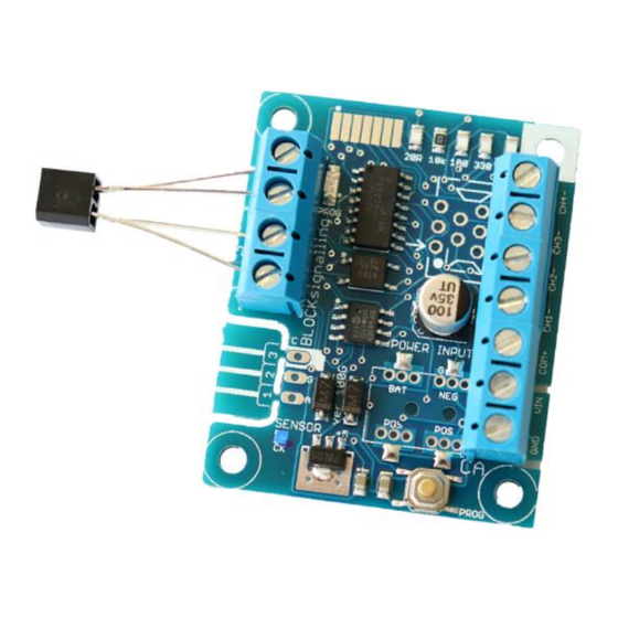
ASPECT CONTROLLER ASP1A
(FOR COMMON CATHODE LED SIGNALS)
Uses an infra-red sensor mounted below the track to detect trains passing above
When a train is detected, the module triggers the signal to switch to red
Signal automatically switches back to green (through yellow and double-yellow if
appropriate)
Flexible programming options to suit different signals and to allow adjustment of
timings to suit
Designed for signals which need +12V to be switched to them to light their leds
(common cathode)
Realistic fading between aspects.
Yellow and Double-Yellow stages will change to red if another train passes.
Building on the success of our infra-red train detectors, this module boasts a wider
range of input voltages, smooth fading between aspects, and the ability to be
triggered from yellow or double-yellow stages back to red.
This Signal Controller detects trains by bouncing invisible Infra-Red (IR) light off the
underside of the rolling stock, and detecting the light reflected back. Once triggered
by the train, the module runs built-programs to simulate the operation of 2-, 3- or 4-
aspect signals.
Advertisement

Related Manuals for BLOCKsignalling ASP1A


Summary of Contents for BLOCKsignalling ASP1A
- Page 1 ASPECT CONTROLLER ASP1A (FOR COMMON CATHODE LED SIGNALS) Uses an infra-red sensor mounted below the track to detect trains passing above When a train is detected, the module triggers the signal to switch to red Signal automatically switches back to green (through yellow and double-yellow if appropriate) ...
- Page 2 BLOCKsignalling www.blocksignalling.co.uk The signal normally shows green. When the train passes the detector, the signal switches to red. Once the train has fully cleared the detector, the module switches the signal back to green (via yellow and double-yellow if appropriate).
- Page 3 BLOCKsignalling www.blocksignalling.co.uk Programming As supplied, the module is programmed for 4-aspect signals. If you are using 3- or 2-aspect signals, then it will be necessary to reprogram the module. Programming for the particular application can be completed before or after testing the wiring, and also before or after completing the installation.
-
Page 4: Factory Reset
BLOCKsignalling www.blocksignalling.co.uk Factory Reset To reset the module back to factory settings, switch off the power to the module and hold down the Push Button. Apply the power and continue holding the push button until 1 flash of the led is seen. At this point, release the button. You will see a long flash of five seconds. - Page 5 BLOCKsignalling www.blocksignalling.co.uk Testing the Infra-red Detection An Infra-Red source and Infra-Red detector are moulded into a single 5mm x 6.5mm package that can be located below the track bed to reflect light off rolling stock. Identify the leads from the diagram and connect to the terminals marked A, K, C and E on the PCB.
-
Page 6: Sensitivity Setting
BLOCKsignalling www.blocksignalling.co.uk Sensitivity Setting The module is supplied with the sensitivity pre-set to suit most installations and should not need adjustment. In locations such as tunnels, or when the module is not being used under the track bed, then it may be desirable to adjust the detection threshold. - Page 7 BLOCKsignalling www.blocksignalling.co.uk Installation The Infra-Red sensor is normally installed below the track-bed. The detection range of the unit is up to approximately 25mm from the face of the package when the default sensitivity is set (for dark surfaces with low levels of reflectivity).
-
Page 8: Connecting The Outputs
BLOCKsignalling www.blocksignalling.co.uk Connecting the Outputs Each channel has an output, which switches to 12V to switch the output on. There are resistors built-in to the controller, so external resistors are not required. If your signal already has resistors connected, these can remain if you wish, although the signal may appear slightly dimmer. - Page 9 BLOCKsignalling www.blocksignalling.co.uk To select this program, switch off the power to the module and hold down the Push Button. Apply the power and continue holding the push button until 2 flashes are seen. At this point, release the button. You will see a long flash of two seconds and then the led will begin flashing again.
- Page 10 BLOCKsignalling www.blocksignalling.co.uk The "red time" can be adjusted to a realistic duration for a train to clear the section of track protected by the signal. The "yelllow time" can be adjusted to a realistic duration for the scale. When supplied, or following a factory reset, the module will operate in 4-aspect mode.
- Page 11 BLOCKsignalling www.blocksignalling.co.uk Once the train has cleared the sensor, and the release time expires, then the "red time" timer starts. When this expires, the signal switches to yellow and the "yellow timer" starts. When this expires, the signal switches to double yellow and the "double yellow timer"...
- Page 12 BLOCKsignalling www.blocksignalling.co.uk Connecting Control Panel Leds If you wish to show the status of any signal using separate leds on a control panel, then these can simply be wired in series with the signal leds. The diagram below shows two leds on a control panel, which will show the same colour as the connected 2-aspect signal.
- Page 13 BLOCKsignalling www.blocksignalling.co.uk Example Wiring to Eckon or Berko 4-aspect Signal The positive connection from each of the leds in an Eckon or Berko signal match the led colour (red wire for the red led positive connection, etc). Depending on the age of the signal, there will be one or more white wires. These are the negative connections to the leds.
- Page 14 BLOCKsignalling www.blocksignalling.co.uk Changing the Timing of each Phase The individual time for each of the phases can be adjusted to suit (the default values are shown in the programming diagram below). Once you are happy with the operation of the train detection, you will probably want to change these to more realistic values.
- Page 15 BLOCKsignalling www.blocksignalling.co.uk flashes for 10 seconds). When the button is released, the led flashes 10 times rapidly, and the module starts operating. Other Programming Options There are a number of parameters which can be adjusted if you wish to alter the operation of the module.
- Page 16 BLOCKsignalling www.blocksignalling.co.uk Program Flow Diagram The diagram below shows all the programming options. Programming is performed by inserting a link between the A and K terminals (or by having the detector wired in place) and holding down the Push Button when switching on the power.
- Page 17 BLOCKsignalling www.blocksignalling.co.uk ©blocksignalling.co.uk 2019 Page 17 of 18...
- Page 18 BLOCKsignalling www.blocksignalling.co.uk Troubleshooting If the module is not functioning as expected, please follow these diagnostic tests. 1. The led on the module does not light. Disconnect all the connections except the power supply and connect a link between the A and K terminals. If it now lights, recheck the connections to the IR sensor carefully.
Need help?
Do you have a question about the ASP1A and is the answer not in the manual?
Questions and answers