Table of Contents
Advertisement
Advertisement
Table of Contents
Troubleshooting

Subscribe to Our Youtube Channel
Related Manuals for Omron MS4800E


Summary of Contents for Omron MS4800E
- Page 1 Cat. No. F04E-EN-02 Safety Light Curtain Type 4 MS4800E OPERATION MANUAL...
- Page 3 MS4800E Safety Light Curtain Type 4 Installation and Operating Manual March 2010 Omron Europe B.V. Wegalaan 67-69 NL-2132 JD, Hoofddorp Pays-Bas Tel.: +31 (0) 23 568 13 00 Fax: +31 (0) 23 568 13 88 www.industrial.omron.eu...
- Page 5 © OMRON, 2010 All rights reserved. No part of this publication may be reproduced, stored in a retrieval system, or transmitted, in any form, or by any means, mechanical, electronic, photocopying, recording, or otherwise, without the prior written permission of OMRON.
-
Page 7: Table Of Contents
TABLE OF CONTENTS PRECAUTIONS ........xiii Precautions on Safety . - Page 8 Selecting External Device Monitoring (EDM) ........
- Page 9 Cleaning.........
- Page 10 Always heed the following points when using the MS4800 system: 1. Be sure to have MS4800 system handled by a "Responsible Person" who is well aware of and familiar with the machine to be installed.
- Page 11 The following are some examples of applications for which particular attention must be given. This is not intended to be an exhaustive list of all possible uses of the products, nor is it intended to imply that the uses listed may be suitable for the products: Outdoor use, uses involving potential chemical contamination or electrical interference, or conditions or uses not described in this document.
- Page 12 Product specifications and accessories may be changed at any time based on improvements and other reasons. It is our practice to change model numbers when published ratings or features are changed, or when significant construction changes are made. However, some specifications of the product may be changed without any notice.
-
Page 13: Precautions
PRECAUTIONS Precautions on Safety In order to use the MS4800 system safely, the precautions listed in this man- ual indicated by alert symbols and descriptions must be followed. Failure to follow all precautions and alerts may result in an unsafe use or operation. -
Page 14: Alert Statements In This Manual
Install the sen- sors so that part of the person is always present in the detection zone when working in a machine's hazardous areas. If a person is able to step into the... - Page 15 Do not short-circuit the output line to the +24 V line. Otherwise, the output is always ON. Also, the 0 V of the power supply must be grounded so that output does not turn ON due to grounding of the output line.
- Page 16 Double or reinforced insulation from hazardous voltage must be applied to all input and output lines. Failure to do so may result in electric shock. !WARNING Extension of the cable must be within a specified length. If it isn't, safety func- tion may not work properly, resulting in danger. Other...
-
Page 17: Precautions For Safe Use
• Not used with a current that is higher than the rating • Do not drop the product • Dispose of the product in accordance with the relevant rules and regula- tions of the country or are where the product is used. -
Page 18: Precautions For Correct Use
• Areas where the product may come into contact with water • Areas where the product may get wet with oil that can solve adhesive Do not use radio equipment such as cellular phones, walkie-talkies, or trans- ceivers near the MS4800 system. -
Page 19: Important Safety Warnings
• The operating instructions must be made available to the operator of the machine where the MS4800 system is installed. • The machine operator is to be instructed in the use of the device by spe- cialist personnel and must be instructed to read the operating instructions. -
Page 20: Section 2
Section... -
Page 21: Product Features
SECTION 2 Product features The MS4800 safety light curtain family is available in two versions. These ver- sions are identified as the MS4800-EA and EB versions. Configuration of the safety light curtains can be changed through selector switches located under an access cover. -
Page 22: System Components And Indicators
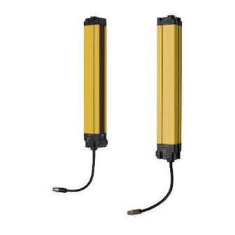
SECTION 3 System Components and Indicators Chart Chart Receiver Transmitter Individual beam Indicators (one with every beam) - Detection Zone Red LED Blanking Active - Amber LED Flip door, Access to configuration switches (on transmitter and receiver) INTERLOCK or ALARM indicator - Yellow LED... -
Page 23: System Operation
The two receiver safety outputs are in the ON state, the green MACHINE RUN indicator is lit, and the auxiliary output is in a state consistent with its configu- ration. The protected machine is allowed to operate. Pressing and releasing the start button has no effect. -
Page 24: Operating Modes
MS4800FS Requirements The MS4800FS is offered in protective heights ranging from 280 mm to 1800 mm for 14 mm resolution and 280 mm to 2120 mm for 30 mm resolu- tion. • An MS4800FS system has a maximum size limitation based on the num- ber of beams. - Page 25 The MS4800FS will enter a fault condition, indicated by error code "95" on the indicators in the bottom part of the device. This fault code indicates that there was a reduction in the number of cascaded segments. If the number of segments is reduced while power is off, the light curtain will power on with fault code "100".
- Page 26 MS4800FS Cascaded Series Section 4-3...
-
Page 27: Detection Options
Each Fixed Blanked area has a size and positional tolerance of ±1 beam to allow for slight position variance and only the two beams on the edges of the blanked area are allowed to vary. Because of this position tolerance, a reduc- tion of the optical resolution takes place on the border area of Fixed Blanking patterns. - Page 28 Blanked areas. For only this case, there is no positional tolerance allowed on that side of the clear beam for the object closest to the entry endcap so that clear beam can only be used by the object further away from the entry end- cap.
- Page 29 Start switch is activated to clear the fault. When the receiver powers up it will be in Fixed Blanking mode with the red and amber LEDs lit. 2. The authorized user then...
- Page 30 Blanking switches off and in Fixed Blanking is disabled. then on. The user may start normal operation by a press and release of the start button or by per- forming a power cycle. 6. To exit Fixed Blanking the user sets both selector IBIs of blocked beams on.
-
Page 31: Floating Blanking
Please refer to chapter 5-4 Opti- cal Synchronization for further details. This means that an object can freely float from one end of the protective field to the other without the MS4800 system entering the MACHINE STOP state. -
Page 32: Fixed Blanking With Floating Blanking
The increase is equal to the beam spacing distance for each beam that is disabled. If the size of the object detected by the system increases the minimum safe distance must also be increased. Use the minimum object sensitivity given in the following tables to determine the new figure to use when computing the safety distance. -
Page 33: Optical Synchronization
To establish synchro- nization the system needs to have a certain number of consecutive clear beams (see following table) within the first master segment. If they are not sat- isfied, the system will enter a MACHINE STOP state and every other Individ- ual Beam Indicator will light. - Page 34 Optical Synchronization Section 5-4...
-
Page 35: Diagnostic And Test Features
The MS4800 offers operating range selection: short range is 3 m and long range is 7 m for the 14 mm models. For the 30mm models the short range is 8m and long range is 20 m. This function is useful when there are many light curtains operating within a small space and the possibility of cross-talk is likely. -
Page 36: Start/Restart Input
Start/Restart Input Section 6-5 Start/Restart Input The characteristic of the Start/Restart Input is shown in the following sche- matic: +24 VDC Start MS4800 +24 VDC N.O. 0 VDC Reset... -
Page 37: Using Selector Switches To Set Features
Using selector switches to set features !WARNING Make sure that foreign objects such as water, oil, or dust do not enter the inside of the MS4800 system while the cover for the selector switches is open. Access to the selector switches The switches are located behind a flip door on both the transmitter and receiver. -
Page 38: Operating Mode Selection
Selecting External Device Monitoring (EDM) EDM is activated by setting position 2 of Switches A and B located on the receiver. Any mismatch between the settings of Switches A and B will result in an alarm condition. -
Page 39: Selecting Scan Codes
Selecting Scan Codes The MS4800 receiver and transmitter offer scan code selection to minimize cross talk. On the transmitter this is activated by setting position 1. On the receiver this is activated by setting position 3 of switch A and switch B. - Page 40 Selecting Scan Codes Section 7-7...
-
Page 41: Outputs
This is not a safety output. The MS4800 system supplies one auxiliary output. The configuration of this output is "PNP follow". So the signal on the auxiliary output is similar to the status of the OSSD outputs. It will source up to 100 mA at 24 VDC. - Page 42 Auxiliary Output Section 8-2...
-
Page 43: Safe Mounting Distances
An MS4800 system must be mounted far enough from the machine danger zone so the machine will stop before a hand or other body part reaches the hazardous area. This distance is called the safety distance. It is a calculated number based on a formula. - Page 44 If the result of the calcula- tion is less than 100 mm, a distance of at least 100 mm must still be maintained. Approach speed in mm/s. In the close area of 500 mm, the speed is calculated at 2000 mm/s.
-
Page 45: Safety Distance For Safeguarding Danger Areas
Additional countermeasures may be necessary to prevent access to the dan- gerous area from above, below, the sides or the rear of the machine. The height of the protective field "H" above the reference plane and the reso- lution "d" of the MS4800 system have the following relationship:... -
Page 46: Safety Distance And Beam Heights In Access Guarding
128 mm EN 294 EN 294 The height of the protective field "H" above the reference plane and the reso- lution "d" of the MS4800 system have the following relationship: (K x T) + C For K and T please refer to the previous chapter... -
Page 47: Installation
SECTION 10 Installation !WARNING Install the sensor system so that it is not affected by reflective surfaces. Fail- ure to do so may hinder detection, resulting in serious injury. 10-1 Reflective Surface Interference A reflective surface adjacent to the detection zone can deflect the optical beam and may cause an obstruction in the zone not to be detected. -
Page 48: Cross Talk Mitigation
To mitigate interference from other light curtains, the MS4800 system has two possible scan codes, A and B. The transmitter and receiver units must be set to the same scan code for the receiver to enter the MACHINE RUN state. -
Page 49: General Mounting Considerations
10-3 General Mounting Considerations 10-3-1 Additional Guarding Areas of access to the point of hazardous operation not guarded by the MS4800 system must be protected by suitable means such as a fixed barrier guard, an interlocked guard or a safety mat system. - Page 50 The system detection zone is delineated by the inside edge of the transmitter and receiver endcaps. The area outside these marks is not protected. Position the system so that it is only possible to access the danger point through the detection zone.
- Page 51 In this case, the guarded machine must only be restarted using a switch located outside and with a full view of the area of hazardous motion. Opera- tion of the MS4800 system In the Start/Restart Interlock operating mode is suitable for perimeter guarding.
- Page 52 General Mounting Considerations Section 10-3...
-
Page 53: Connection To The Machine Control Circuit
!WARNING Never use only a single safety output to control the machine. Should this sin- gle output fail, the machine may not stop, resulting in severe operator injury. The machine must be connected using both safety outputs. -
Page 54: Interconnect Cables For Cascaded Ms4800Fs System
The maximum cable length is 10 meters between segments. The extension cables are available in lengths of 0.3 m, 0.5 m, 1 m, 2 m, 5 m and 10 m. A MS4800FS system does not require an extension cable; it has a 150 mm integrated cable (pigtail). -
Page 55: Connection To Two Forcibly Guided Relays
Connection to two forcibly guided relays Section 11-2 11-2 Connection to two forcibly guided relays G7S and G7SA series relays provide forcibly guided relay outputs for machine control. Please refer to the next drawing for details: Power supply Fuse +24VDC Protective Earth MTS requires a NC contact. - Page 56 Connection to a safety relay unit Section 11-3...
-
Page 57: Muting
Install muting sensors so that they can distinguish between the object that is being allowed to pass through the detection zone and a person. If the muting function is activated by the detection of a person, it may result in serious injury. - Page 58 3. The MS4800 system performs a system reboot. When this sequence is properly completed, muting function is enabled. The status LED of the receiver turns to green and the status LED of the RM6 lights permanently. When this sequence is properly completed, the system will enable muting.
-
Page 59: Checkout And Test Procedure
13-2 Test Procedure !WARNING The tests outlined in the Test Procedure in Appendix B must be performed at installation, according to the employer's regular inspection program and after any maintenance, tooling change set up, adjustment or modification to the MS4800 system or the guarded machine. - Page 60 Using the test object Section 13-3...
-
Page 61: Cleaning
SECTION 14 Cleaning Accumulation of oil, dirt and grease on the front window of the MS4800 trans- mitter and receiver can effect the system operation. Clean the window with a mild detergent or glass cleaner. Use a clean, soft, lint-free cloth. Painted MS4800 surfaces may be cleaned with a mild de-greasing cleaner or deter- gent. - Page 62 Section...
-
Page 63: Specifications And Additional Information
14 mm and 30 mm Operating Range 0.3 m - 7 m (14 mm resolution), DIP SW 6 option 0.3 m - 3 m (14 mm resolution), default 0.3 m - 20 m (30 mm resolution), DIP SW 6 option 0.3 m - 8 m (30 mm resolution), default... - Page 64 Must meet the requirements of EN/IEC 60204-1 and EN/IEC 61496-1, and must guarantee safe insulation from the mains voltage in accordance with IEC 60742 and be able to cover a drop of supply voltage of at least 20 ms. Protection class...
- Page 65 Category 4 acc. EN954-1 (1996) Safety Integrity Level MS4800E system is suitable for up to SIL 3 per IEC 61508 3,5 * 10 Proof test interval Every 2 years (based on max. number of channels in a 4 segment system including muting system).
-
Page 66: Ms4800 System Dimensional Drawing
MS4800 system Dimensional Drawing Section 15-2 15-2 MS4800 system Dimensional Drawing 30.2 [1.19] 62.9 [2.48] BRACKET ROTATION 90.0 ° VIEWS 53.6 [2.11] 59.2 [2.33] 38.1 [1.50] 40.1 [1.58] 49.1 [1.93] DIA.6.8 [.27] 23.2 [.91] 52.8 [2.08] 37.3 [1.47] 27.6 [1.09] 58.6 [2.31]... -
Page 67: Ms4800 System Data With 14 Mm Resolution
MS4800 system data with 14 mm resolution Section 15-3 15-3 MS4800 system data with 14 mm resolution 280 mm 320 mm 360 mm 400 mm 440 mm 480 mm 284,4 324,8 364,5 404,2 443,9 484,3 420,4 460,8 500,5 540,2 579,9... -
Page 68: Ms4800 System Data With 30 Mm Resolution
1021,1 746,9 784,9 826,4 866,7 905,7 946,7 810,9 848,9 890,4 930,7 969,7 1010,7 Weight 3,54 kg 3,76 kg 3,90 kg 4,08 kg 4,26 kg 4,45 kg Number of Beams * This size is not available for Master or Standalone models. - Page 69 MS4800 system data with 30 mm resolution Section 15-4 960 mm 1000 mm 1040 mm 1080 mm 1120 mm 1160 mm 963,6 1002,6 1042,9 1083,9 1122,3 1162,7 1099,6 1138,6 1178,9 1219,9 1258,3 1298,7 1060,9 1099,9 1140,2 1181,2 1219,6 1260,0 986,5...
-
Page 70: Ms4800Fs System Dimensional Drawing
MS4800FS system Dimensional Drawing Section 15-5 15-5 MS4800FS system Dimensional Drawing 30.1 [1.19] 62.9 [2.48] BRACKET MULTIPLE ROTATION FLEX SEGMENTS ° ° 90.0 VIEWS 53.6 [2.11] 40.1 [1.58] 59.2 [2.33] DIA 6.8 [.27] 38.1 [1.50] 52.8 [2.08] 49.1 [1.93] 27.8 [1.09] 23.2 [.91]... -
Page 71: Ms4800Fs System Data With 14 Mm Resolution
1307,9 1045,0 1084,0 1124,3 1165,3 1203,7 1244,1 1090,3 1129,3 1169,6 1210,6 1249,0 1289,5 Weight 4,63 kg 4,81 kg 4,99 kg 5,17 kg 5,35 kg 5,53 kg Number of Beams * This size is not available for Master or Standalone models. -
Page 72: Ms4800Fs System Data With 30 Mm Resolution
589,1 326,0 365,8 401,4 445,9 481,4 525,3 371,3 411,1 451,5 491,2 530,9 570,6 Weight 1,55 kg 1,68 kg 1,81 kg 1,95 kg 2,13 kg 2,40 kg Number of Beams * This size is not available for Master or Standalone models. - Page 73 MS4800FS system data with 30 mm resolution Section 15-7 480 mm 520 mm 560 mm 600 mm 640 mm 680 mm 484,3 523,4 563,7 604,1 643,9 683,6 620,3 659,4 699,7 740,1 779,9 819,6 601,8 640,9 681,2 721,6 761,4 801,1 581,6...
- Page 74 MS4800FS system data with 30 mm resolution Section 15-7 1440 mm 1480 mm 1520 mm 1560 mm 1600 mm 1640 mm 1443,4 1481,8 1521,5 1563,3 1600,9 1641,3 1579,4 1617,8 1657,5 1699,3 1736,9 1777,3 1560,9 1599,3 1639,0 1680,8 1718,4 1758,8 1540,7...
-
Page 75: List Of Models
List of models Section 15-8 15-8 List of models Basic version, 14 mm resolution, Standalone units without Flex connection Type Name Version Resolution Length Operation [mm] [mm] MS4800S-EB-014-0280 Basic 14 mm Standalone MS4800S-EB-014-0320 Basic 14 mm Standalone MS4800S-EB-014-0360 Basic 14 mm... - Page 76 List of models Section 15-8 Advanced version, 14 mm resolution, Standalone unit without Flex connection Type Name Version Resolution Length Operation [mm] [mm] MS4800S-EA-014-0280 Advanced 14 mm Standalone MS4800S-EA-014-0320 Advanced 14 mm Standalone MS4800S-EA-014-0360 Advanced 14 mm Standalone MS4800S-EA-014-0400 Advanced...
- Page 77 List of models Section 15-8 Basic version, 30 mm resolution, Standalone unit without Flex connection Type Name Version Resolution Length Operation [mm] [mm] MS4800S-EB-030-0280 Basic 30 mm Standalone MS4800S-EB-030-0320 Basic 30 mm Standalone MS4800S-EB-030-0360 Basic 30 mm Standalone MS4800S-EB-030-0400 Basic...
- Page 78 List of models Section 15-8 Advanced version, 30 mm resolution, Standalone unit without Flex connection Type Name Version Resolution Length Operation [mm] [mm] MS4800S-EA-030-0280 Advanced 30 mm Standalone MS4800S-EA-030-0320 Advanced 30 mm Standalone MS4800S-EA-030-0360 Advanced 30 mm Standalone MS4800S-EA-030-0400 Advanced...
- Page 79 List of models Section 15-8 Basic version, 14 mm resolution, Cascadable, Master unit Type Name Version Resolution Length Operation [mm] [mm] MS4800FS-EB-014-0280 Basic 14 mm Master MS4800FS-EB-014-0320 Basic 14 mm Master MS4800FS-EB-014-0360 Basic 14 mm Master MS4800FS-EB-014-0400 Basic 14 mm...
- Page 80 List of models Section 15-8 Advanced version, 14 mm resolution, Cascadable, Master unit Type Name Version Resolution Length Operation [mm] [mm] MS4800FS-EA-014-0280 Advanced 14 mm Master MS4800FS-EA-014-0320 Advanced 14 mm Master MS4800FS-EA-014-0360 Advanced 14 mm Master MS4800FS-EA-014-0400 Advanced 14 mm...
- Page 81 List of models Section 15-8 Slave operation model, 14 mm resolution, Cascadable, Slave unit Type Name Version Resolution Length Operation [mm] [mm] MS4800F-E-014-0240 n.a. 14 mm Slave MS4800F-E-014-0280 n.a. 14 mm Slave MS4800F-E-014-0320 n.a. 14 mm Slave MS4800F-E-014-0360 n.a. 14 mm...
- Page 82 List of models Section 15-8 Basic version, 30 mm resolution, Cascadable, Master unit Type Name Version Resolution Length Operation [mm] [mm] MS4800FS-EB-030-0280 Basic 30 mm Master MS4800FS-EB-030-0320 Basic 30 mm Master MS4800FS-EB-030-0360 Basic 30 mm Master MS4800FS-EB-030-0400 Basic 30 mm...
- Page 83 List of models Section 15-8 Advanced version, 30 mm resolution, Cascadable, Master unit Type Name Version Resolution Length Operation [mm] [mm] MS4800FS-EA-030-0280 Advanced 30 mm Master MS4800FS-EA-030-0320 Advanced 30 mm Master MS4800FS-EA-030-0360 Advanced 30 mm Master MS4800FS-EA-030-0400 Advanced 30 mm...
- Page 84 List of models Section 15-8 Slave operation model, 30 mm resolution, Cascadable, Slave unit Type Name Version Resolution Length Operation [mm] [mm] MS4800F-E-030-0280 n.a. 30 mm Slave MS4800F-E-030-0320 n.a. 30 mm Slave MS4800F-E-030-0360 n.a. 30 mm Slave MS4800F-E-030-0400 n.a. 30 mm...
-
Page 85: Accessories
15-9-1 Muting controller MS4800-RM6 22.5 0.89 S11 S12 Lamp Shield 0VDC +VDC RM-6 3.90 3.90 Status 4.49 Note Required cable to connect MS_800FS-EA-_ to MS4800-RM6 module is MS4800-CBLMT_M 15-9-2 Safety Relay Units Family Type Name Configuration G9SB G9SB-200-D DPST-NO G9SB-301-D 3PST-NO G9SA G9SA-301... - Page 86 Transmitter Interconnect Cable, 3,0 m length F39-JMCT-5M Transmitter Interconnect Cable, 5,0 m length F39-JMCT-10M Transmitter Interconnect Cable, 10 m length Note Max length of interconnect cable 10 m Combination Example: Transmitter Master/Slave 10 m -> Slave 1 10 m -> Slave 2 10 m ->...
- Page 87 Section 15-9 15-9-5 Explosion Proof Kit for MS4800 Designed for use in explosive environments, the MS4800-EPKT kit consists of a transmitter and receiver housing. The explosion proof kit for MS4800 is available in 4 sizes: MS4800-EPKT-0320 Explosion proof housing for...
- Page 88 Accessories Section 15-9...
-
Page 89: Glossary
ESPE power or by a Start signal transition. MACHINE RUN When the ESPE is in this state, the two OSSD are both active. In this state the Green MACHINE RUN LED is on, the red MACHINE STOP LED is off and the Yellow INTERLOCK LED is off. - Page 90 Section...
-
Page 91: Diagnostics And Troubleshooting
The receiver first segment has a set of LEDs to indicate diagnostic codes. The LEDs will only indicate error codes, if it is in an error condition. In this state the yellow INTERLOCK LED will be flashing and a row of 10 LEDs will display the fault code. -
Page 92: Receiver Troubleshooting
SECTION 12 Muting for further information. 5. Verify the control relays are within operating limits of the safety outputs. 6. Verify the cable lengths from the light curtain to the control relays are within specified limits. 7. If this does not solve the problem, please contact your local Omron distrib- utor or the European Repair Center. - Page 93 Segment count is less than original configu- reduced (changed) ration. Add required segment(s) or program system for current configuration Too many flex nodes or muting modules in Make sure of total of 4 segments with only the flex bus one muting module.
-
Page 94: Faq
3. The Power Supply must be deactivated and immediately activated. The MS4800 will be now in the Fixed Blanking mode and the red as well as the amber LEDs will lit. 4. Please deactivate Fixed Blanking (both nr. 5 switches to off). -
Page 95: Appendix
18-1 Appendix A Checkout procedure log The following checkout procedure must be performed by qualified personnel during initial MS4800 system installation and at least every three months or more frequently depending on machine usage and company guidelines. Machine identification____________________________ Date____________... -
Page 96: Appendix B
MS4800 system or the guarded machine. Testing ensures that the light cur- tain, safety system, and machine control system work together to properly stop the machine. Failure to test properly could result in serious injury to per- sonnel. To test the MS4800 system, use the correct size test object. -
Page 97: Ec Declaration Of Conformity
EC Declaration of Conformity Section 18-3 18-3 EC Declaration of Conformity... -
Page 98: Revision History
Revision History A manual revision code appears as a suffix to the catalog number on the front cover of the manual. Cat. No. F04E-EN-02 Revision code The following table outlines the changes made to the manual during each revision. Page numbers refer to the previous version.
Need help?
Do you have a question about the MS4800E and is the answer not in the manual?
Questions and answers