Advertisement
Quick Links
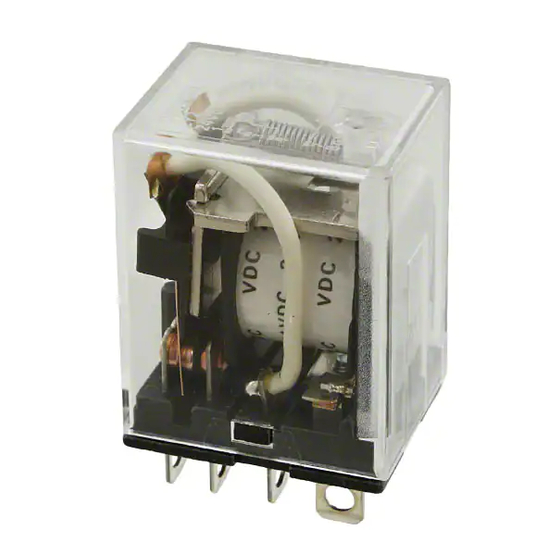
General-purpose Relay
LY
A Miniature Power Relay
• Equipped with arc barrier.
• Dielectric strength: 2,000 V.
• Built-in diode models added to the LY Series.
• Single-pole and double-pole models are applicable to operating
coils with ratings of 100/110 VAC, 110/120 VAC, 200/220 VAC,
220/240 VAC, or 100/110 VDC).
• Three-pole and four-pole models are applicable to operating
coils with ratings of 100/110 VAC, 200/220 VAC, or 100/110
VDC).
Ordering Information
■ Open Relays
Type
Contact form
Standard
SPDT
DPDT
DPDT (bifurcated)
3PDT
4PDT
With built-in diode
SPDT
(DC only)
DPDT
DPDT (bifurcated)
3PDT
4PDT
With built-in CR
SPDT
(AC only)
DPDT
DPDT (bifurcated)
Note: 1. When ordering, add the rated coil voltage to the model number. Rated coil voltages are given in the coil ratings table.
Example: LY2, 6 VAC
2. Relays with #187 quick connect terminals are also available with SPDT and DPDT contact. Ask your OMRON representative for details.
3. SEV models are standard Relays excluding DPDT (bifurcated) models.
4. VDE- or LR- qualifying Relays must be specified when ordering.
Plug-in/solder
terminals with LED
terminals
LY1
LY1N
LY2
LY2N
LY2Z
LY2ZN
LY3
LY3N
LY4
LY4N
LY1-D
LY1N-D2
LY2-D
LY2N-D2
LY2Z-D
LY2ZN-D2
LY3-D
---
LY4-D
LY4N-D2
---
---
LY2-CR
LY2N-CR
LY2Z-CR
LY2ZN-CR
Rated coil voltage
Plug-in/solder
PCB terminals
indicator
LY1-0
LY2-0
LY2Z-0
LY3-0
LY4-0
---
---
---
---
---
---
---
---
General-purpose Relay
LR
Upper-mounting
Plug-in/solder
terminals
LY1F
LY2F
LY2ZF
LY3F
LY4F
---
---
---
---
---
---
---
---
LY
A-31
Advertisement

Related Manuals for Omron LY


Summary of Contents for Omron LY
- Page 1 DPDT (bifurcated) LY2Z-CR LY2ZN-CR Note: 1. When ordering, add the rated coil voltage to the model number. Rated coil voltages are given in the coil ratings table. Example: LY2, 6 VAC Rated coil voltage 2. Relays with #187 quick connect terminals are also available with SPDT and DPDT contact. Ask your OMRON representative for details.
-
Page 2: Specifications
PTF14A-E, PTF14A PT14 PT14QN PT14-0 Note: 1. For PTF08-E and PTF14A-E, see “Track Mounted Socket.” 2. PTF@A (-E) Sockets have met UL and CSA standards: UL 508/CSA C22.2. Mounting Plates for Sockets Socket model For 1 Socket For 10 Sockets... - Page 3 32 H 63.7 H Note: 1. The rated current and coil resistance are measured at a coil temperature of 23 C with tolerances of +15%/–20% for rated currents and 15% for DC coil resistance. 2. Performance characteristic data are measured at a coil temperatures of 23 C.
- Page 4 Single- and double-pole standard, bifurcated-contact Relays: –25 C to 55 C (with no icing) (–25 C to 70 C if carry current is 4 A or less) All other Relays: –25 C to 40 C (with no icing) (–25 C to 55 C if carry current is 4 A or less) Ambient humidity...
- Page 5 Conditions Operating frequency Electrical life 100 VAC AC motor 400 W, 100 VAC single-phase with 35-A in- ON for 10 s, OFF for 50 s 50,000 operations rush current, 7-A current flow AC lamp 300 W, 100 VAC with 51-A inrush current,...
- Page 6 3 and 4 10 A, 30 VDC (Resistive) 6 x 10 10 A, 240 VAC (General use) 1/3 HP, 240 VAC CSA 22.2 No. 14 Listings (File No. LR31928) No. of poles Coil ratings Contact ratings Operations 6 to 240 VAC...
-
Page 7: Engineering Data
7 ms 1,000 DC resistive load 24 VDC 110 VAC (cos = 0.4) (L/R = 7ms) 500 1,000 10 12 14 16 18 20 Switching voltage (V) Switching current (A) Maximum Switching Power Endurance AC resistive load Life: 500,000 operations... - Page 8 7 ms 24 VDC (L/R = 7ms) Life: 500,000 operations 500 1,000 Switching voltage (V) Switching current (A) Dimensions Note: All units are in millimeters unless otherwise indicated. Relays with Solder/Plug-in Terminals LY1N (-D2) LY1-D Eight, 2-dia. holes 28 max. 21.5 max.
- Page 9 LY2(Z) Eight, 3-dia. holes 28 max. 21.5 max. 36 max. LY2(Z)N LY2(Z)N-D2 DC Model AC Model Note: The DC models have polarity. LY3Z LY3N LY3-D 28 max. 31.5 max. 36.5 max. Eleven, 3-dia. holes Terminal Arrangement/Internal Connections (Bottom View) LY3-D...
- Page 10 2. This figure is 6.4 for the LY1-0 Note: 1. The tolerance for the above figures is 0.1 mm. 2. Besides the terminals, some part of the LY1-0 car- ries current. Due attention should be paid when mounting the LY1-0 to a double-sided PC board.
- Page 11 38 0.1 max. Eight, 2-dia. Two, 3.5-dia. holes (see note) 35.5 max. holes (or Two M3 holes) Note: 1. Eight 3-dia. holes should apply to the LY2F model. LY3F 32 max. 28.5 38 0.1 44 max. max. Eleven, Two, 3.5-dia. holes 3-dia.
- Page 12 The following Socket heights should be maintained. Back-connecting Front-connecting 40 (57) 67 (84) Note: 1. The PTF@A (-E) can be track-mounted or screw-mounted. 71 (see note) 2. For the LY@-CR (CR circuit built-in type) model, this figure should be 88. PTF@A (-E) Sockets PTF08A-E PTF11A PTF14A-E...
- Page 13 ■ Hold-down Clips Hold-down clips are used to hold Relays to Sockets and prevent them from coming loose due to vibration or shock. Used with Socket Used with Socket For CR circuit built-in Relay mounting plate PYC-P PYC-S PYC-1 PYC-A1...
- Page 14 ALL DIMENSIONS SHOWN ARE IN MILLIMETERS. To convert millimeters into inches, multiply by 0.03937. To convert grams into ounces, multiply by 0.03527. In the interest of product improvement, specifications are subject to change without notice. Cat. No. J002-E1-10 A-44 General-purpose Relay...
Need help?
Do you have a question about the LY and is the answer not in the manual?
Questions and answers