Advertisement
Table of Contents
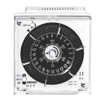
24-hour/Weekly Time Switch
H2F
Up to 96 ON/OFF Cycles from DIN-sized
(72 x 72 mm) Timer
• Easy setting with color-coded programming tabs.
• Choose from 24-hour or 1-week models with either SPST-NO or
SPDT control outputs.
• Minute dial assures accurate settings.
• Models with memory protection available.
• Control outputs can be manually turned ON/OFF.
• Designed for surface, flush, or track mounting.
Model Number Structure
Model Number Legend
H2F-@@@@
1 2 3 4
1. Operation cycle
D:
24-hour
W:
1-week
2. Motor type
None: Synchronous motor
M:
Quartz motor
3. Mounting method
None: Flush mounting
F:
Surface mounting, DIN track mounting
4. Output type
None: SPST-NO
C:
SPDT
24-hour/Weekly Time Switch
H2F
1
Advertisement
Table of Contents

Related Manuals for Omron H2F


Summary of Contents for Omron H2F
- Page 1 Up to 96 ON/OFF Cycles from DIN-sized (72 x 72 mm) Timer • Easy setting with color-coded programming tabs. • Choose from 24-hour or 1-week models with either SPST-NO or SPDT control outputs. • Minute dial assures accurate settings. • Models with memory protection available.
-
Page 2: Ordering Information
Note: 1. The 24-hour models are supplied with three pairs of programming tabs. The 1-week models are supplied with seven pairs of programming tabs. 2. A Rechargeable Battery is provided in the H2F. When the life of the Battery has expired, order a replacement using this model number. Specifications... - Page 3 150 g Surface mounting:approx. 200 g Note: 1. Accuracy of operating time of when the H2F is ON or when the H2F is OFF. 2. Difference between the set and actual operation time with the pointer set to the present time.
- Page 4 Specified torque: 0.8 N·m Maximum torque: 0.98 N·m 3: When connecting leads to the terminal block, use the same wire size for all leads. If different wire sizes are used, the thinner leads may come off during operation. 4: Recommended lead wires: AWG18 to AWG24 (cross-section: 0.205 to 0.823 mm ), solid or twisted wire 5: When using crimp terminals, connect a maximum of two crimp terminals to any one terminal.
- Page 5 Dimensions Note: All units are in millimeters unless otherwise indicated. Mounting Dimensions Surface Mounting: H2F-DF/-DMF/-WMF Track Mounting: H2F-DFC/-DMFC/-WMFC Mounting Holes M3.5 Two, M3 holes Screw size M3 x 45 (included) Flush Mounting: H2F-D/-DM/-WM/-DC/-DMC/-WMC 65.5 Panel Cutout Recommended panel thickness: 1 to 3.2 mm Note: The mounting adapter and screws are included.
-
Page 6: Time Setting
H2F is mounted in the panel, engage the H2F to part A of the adapter and push it in the direction of B. Then 1. To mount the adapter to the panel cutout, first deform the adapter tighten the two screws as described in 2. -
Page 7: Manual Switch
Be sure to load the Battery with the correct polarity. The polarity is across terminals 4 and 5) is turned ON and load 2 (across 5 and 6) is indicated in the battery box. After loading the Battery, be sure to turned OFF. - Page 8 ALL DIMENSIONS SHOWN ARE IN MILLIMETERS. To convert millimeters into inches, multiply by 0.03937. To convert grams into ounces, multiply by 0.03527. Cat. No. L013-E1-05 In the interest of product improvement, specifications are subject to change without notice.
Need help?
Do you have a question about the H2F and is the answer not in the manual?
Questions and answers