Advertisement
Table of Contents
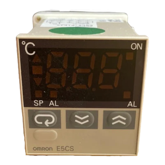
Temperature Controller
DIN-sized (48 48 mm) Temperature
Controller Features Automatic P
(proportional action) Tuning Function
Accurate to 0.5% of full scale.
Multiple temperature ranges allow easy selection
for application.
Field-selectable temperature ranges in C and F.
Easy-to-read, 11-mm high LED digital display.
Tamper-proof setting, faulty-sensor detection, and
controller diagnostics.
8-function alarm available.
Nonvolatile memory.
Field-selectable control mode (ON/OFF or PID).
Ordering Information
Thermocouple Type
Standard temperature ranges
(switch selectable)
Temperature unit (selectable)
Measurement unit
Control mode
Without alarm
ou a a
Relay output
Voltage output
With alarm
a a
Relay output
Voltage output
K (CA) Chromel-alumel
Input
In ut
1,000
900
800
700
600
500
400
400
300
300
200
200
100
0
0
0
0
Set no.
0
1
2
C
C
C/ F
ON/OFF or PID
E5CS-RKJX
E5CS-QKJX
E5CS-R1KJX
E5CS-Q1KJX
999
999
600
500
0
0
0
0
3
4
5
6
C/ F
C/ F
C/ F
F
1
E5CS-X
J (IC) Iron-constantan
500
400
300
200
0
0
0
0
6
7
8
9
C
C
C/ F
C/ F
1
Advertisement
Table of Contents

Related Manuals for Omron E5CS-X


Summary of Contents for Omron E5CS-X
-
Page 1: Ordering Information
(proportional action) Tuning Function Accurate to 0.5% of full scale. Multiple temperature ranges allow easy selection for application. Field-selectable temperature ranges in C and F. Easy-to-read, 11-mm high LED digital display. Tamper-proof setting, faulty-sensor detection, and controller diagnostics. 8-function alarm available. - Page 2 E5CS-R1GX Voltage output E5CS-Q1GX The functions can be factory-set for shipment as shown in the table below, depending on the suffix attached to the model number when you place your order. Two suffixes are selectable: “-DIN” or “-F”. Example: E5CS-RKJX-DIN...
- Page 3 Accessories (Order Separately) Protective Cover Y92A-48 The protective cover protects the front panel, particularly the setting section, against dust, dirt, and water drip. It also prevents the set values from being altered due to accidental contact with the setting keys.
-
Page 4: Specifications
Weight Approx. 170 g (main enclosure only) Note: Set values must be within the allowable range limits for alarm values, control outputs, etc. If a set value does not satisfy the following condition, select another range: Minimum of temperature range x T... - Page 5 Sequentially displays the present temperature, set ture is higher than the set tempera- temperature, and an alarm value (in that order) ture, and o lights when it is lower. each time the temperature indication switching The j indicator lights in green if ) key is pressed.
-
Page 6: Operation
1 units. Conversely, if the temperature range is changed from one in which the temperature can be set in 1 units to a range of 0.0 to 50.0 or 0.0 to 99.9, the unit is decreased to 1/10 of the original unit. -
Page 7: Dip Switch Settings
Lower-limit alarm If the alarm mode selector switch is set to “0” or “9”, no alarm value is displayed. Upper- and On models without alarms, no alarm value is displayed. -
Page 8: Control Mode Selection
Pin 1 ON: Temperature Controller performs PID control. Determining Proportional Period Set pin 2 of the DIP switch to OFF to select a proportional period of Reverse output 20 seconds. This is used when PID control is performed with the... -
Page 9: Thermocouple Type
84 C (offset by –16 C) The input shift value can be set within a range of –99 to 99, except with a 0.0 to 99.9 platinum resistance thermometer, where the input This allows the setting of the temperature shift value. Press the tem- shift narrows to a range of –9.9 to 9.9. -
Page 10: Error Messages
Note: 1. The key operations are disabled. 2. The models with alarm output produce alarm output according to the alarm output setting when the message “FFF” is displayed (or blinks), indicating that the temperature has risen above the set temperature range. Similarly, the alarm output is produced when the message ”–”... -
Page 11: Panel Cutout
Dimensions Note: All units are in millimeters unless otherwise indicated. Panel cutout Note: 1. The recommended panel thickness is 1 to 4 mm. 2. The Temperature Controller is contained in a mount- ing bracket, so close side-by-side Temperature Controller mounting is possible. Provide a center-to- center distance of at least 60 mm between two adja- cent Temperature Controllers. - Page 12 ALL DIMENSIONS SHOWN ARE IN MILLIMETERS. To convert millimeters into inches, multiply by 0.03937. To convert grams into ounces, multiply by 0.03527. Cat. No. H032-E1-2A In the interest of product improvement, specifications are subject to change without notice.
Need help?
Do you have a question about the E5CS-X and is the answer not in the manual?
Questions and answers