Table of Contents
Advertisement
Quick Links
Advertisement
Chapters
Table of Contents

Related Manuals for Laird Nextreme EFC Series


Summary of Contents for Laird Nextreme EFC Series
- Page 1 EFC Recirculating Chiller Specification and User Manual...
- Page 2 Laird. All specifications are subject to change without notice. Laird assumes no responsibility and disclaims all liability for losses or damages resulting from use of or reliance on this information. All Laird products are sold subject to the Laird Terms and Conditions of sale (including Laird’s limited warranty) in effect from time to time, a copy of which will be furnished upon request.
-
Page 3: Table Of Contents
Table of Contents Introduction ............................6 Contact information ..........................6 Safety Precautions ..........................7 Guidelines for Safe Operation ......................8 Prevent Hazards ..........................8 Personal Protective Gear ........................ 8 Guidelines Regarding Electrical Equipment ..................8 Inadmissible Operating Conditions ....................9 Specialized Knowledge ........................ - Page 4 Returning the Unit to Service After Decommissioning ..............53 Final Decommissioning or Disposal ....................53 Disposal of Operating Materials ......................53 Disposal of Refrigerant ........................54 Return of the Unit to Laird Thermal Systems ..................54 Return Procedure ..........................55 List of figures ............................56...
- Page 5 Revision History User Manual number: ETS-DOC-000018514 DATE DESCRIPTION 18/03/2024 Initial release...
-
Page 6: Introduction
Name of contact at your address • Product data as on identification plate: Type of unit, serial number, part number and year of manufacture Company contact: Mail: Laird Thermal Systems s.r.o. Prumyslová 497 462 11 Liberec Czech Republic Phone: +420 488 575 111 Internet: http://www.lairdthermal.com... -
Page 7: Safety Precautions
Safety Precautions This section provides an overview of all the important safety aspects for optimal protection of personnel as well as safe and trouble-free operation of the equipment. The operating manual and warning instructions specified herein should be reviewed completely by all personnel prior to operating the unit. -
Page 8: Guidelines For Safe Operation
Guidelines for Safe Operation Prevent Hazards Hazards can be prevented by safety-conscious and anticipatory behavior of staff. Individuals working with the unit should keep the following in mind: ▪ Always keep a complete and legible copy of this operating manual (or the location at which it can be found) available at the installation site of the unit. -
Page 9: Inadmissible Operating Conditions
High Temperature Limit on Coolant Return - The maximum allowable coolant return (inlet) is 50°C. It is the responsibility of the customer to ensure that this limit is not exceeded. Laird Thermal Systems recommends a thermal shutoff be used with the equipment connected to the Recirculating Chiller. -
Page 10: Safety And Signaling Equipment Included In The Unit
Safety and Signaling Equipment Included in the Unit The unit is equipped with the following safety equipment: ▪ The maximum pressure in the refrigeration system is limited by a refrigerant high-pressure switch. This switch will turn off the compressor and activate ‘high-pressure alarm’ on the display if the pressure exceeds 28 bar on the compressor discharge line. -
Page 11: Guards
Guards Direct access to hazardous parts or areas of the unit is prevented by the unit covers. The unit covers may only be removed for maintenance or repairs. It must be closed prior operating the unit. Top cover Side cover Figure 1 Guards In Case of Accidents Should you or another person be injured when working with the unit, do the following:... - Page 12 Refrigerant R290 (Propane) The refrigerant used in the unit is classified as highly flammable material. WARNING Highly flammable refrigerant Injuries to persons and significant damage to property can occur in the case of improper handling. ▪ Do not try to drain the refrigerant. ▪...
-
Page 13: Specifications
Compliance EN IEC 61326–1:2020 EN 61010–1:2010, EN 61010-2-11:2019 Intended electromagnetic environment: INDUSTRIAL Nominal capacity rating is given at a 20°C setpoint, 20°C ambient temperature, sea level, and 50Hz operation. For ambient conditions outside this range, please contact Laird Thermal Systems. -
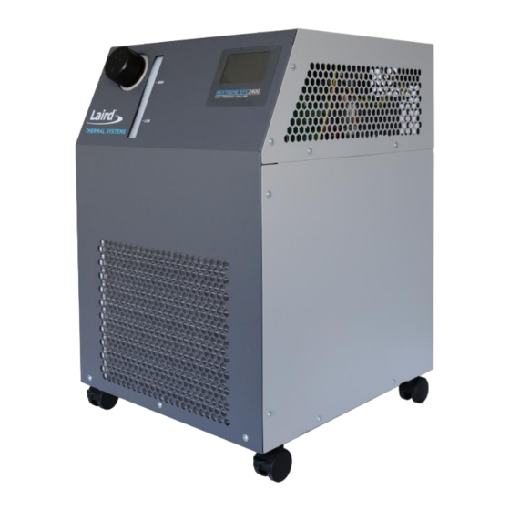
Page 14: Component Locations
Component Locations Figure 2 Isometric Views of Unit Figure 3 Top View... -
Page 15: Figure 4 Front View Figure 5 Rear View
Figure 4 Front View Figure 5 Rear View CONTROL PANEL CONDENSER CONDENSER EVAPORATOR ELECTRONIC EXPANSION VALVE HOT GAS BYPASS VALVE Figure 6 Side Views... -
Page 16: Figure 7 Marking On Unit Figure 8 Labels On Unit
Figure 8 Labels on Unit 1 – Coolant level low marking 2 – Coolant level high marking 3 – Laird serial number label 4 – Flammable label 5 – Coolant return label (to the unit) 6 – Coolant supply label (from the unit) 7 –... -
Page 17: Transport, Packaging And Storage
Transport, Packaging and Storage Safety WARNING Damage due to improper transportation Injuries to persons and significant damage to property can occur in the case of improper transportation. ▪ When unloading the packed unit on delivery, including in-house transport, proceed very carefully and obey the symbols and instructions on the packaging. -
Page 18: Packaging
Symbol Meaning Do not stack This symbol indicates that goods are sensitive to stacking Handle with care This symbol indicates that package must be handled with care Team lift This symbol indicates that two or more persons must be used for lifting as the package is heavy Keep Upright This symbol indicates the goods are sensitive to tilt... - Page 19 a) Cut the straps securing the cardboard box to the pallet. b) Lift the cardboard box and remove from the top. c) Carefully drop the fold down ramp to the floor.
-
Page 20: Handling The Unit While In The Packaging
Then carefully and steadily roll the unit down the ramp. Care should be taken to make sure the unit does not roll off the side of the ramp. Laird advises to keep the transport pallet for later transportation of the unit if necessary. Handling the Unit While in the Packaging... -
Page 21: Transportation On Casters
Transportation on casters The unit is equipped with lockable casters on the front end of the unit. The casters on the back end of the unit are non-lockable. To transport the unit over short distances, the unit can be moved on these casters. - Page 22 Disconnecting the Coolant Hoses. Procedure 1. Pack the unit according to the transport conditions that can be expected. Laird advises to use original packaging, if available, or an equivalent packaging. 2. Mark the packaging with the appropriate symbols. Refer to Symbols on the Packaging.
-
Page 23: Installation Requirements
Installation Requirements 1. Minimum Clearance from obstructions is required as shown to ensure that air intake and air discharge is not blocked as this could affect cooling capacity. Figure 9 Minimum Clearance required for Unit Installation 2. The location must be level. 3. -
Page 24: Installation Procedure
Installation Procedure Connect Hoses NOTE Risk of damage by using improper or faulty coolant hoses This may lead to damage to persons, damage to property, or corrosion damage. ▪ When choosing coolant hoses pay attention to burst pressure, operation temperature and compatibility with coolant. -
Page 25: Disconnect Hoses
Disconnect Hoses The coolant hoses are connected to the unit at the coolant inlet and coolant outlet connections, labeled with respective symbols. Figure 11 Disconnecting Hoses Requirements ▪ Unit prepared for maintenance. Refer to Preparing the Unit for Maintenance. ▪ Coolant cooled to the ambient temperature. -
Page 26: Adding Coolant And Priming Unit
Connecting Power Power cord is not supplied with the unit and must be ordered separately. Please see Laird Thermal Systems product webpage for ordering the power cord. Requirements: ▪ The unit construction provides protection against the risk of electrical shock by grounding appropriate metal parts. - Page 27 Inhibited EG or PG should be used when the coolant is being exposed to aluminum components to prevent galvanic corrosion. Suggested Contaminant Limits: Organics Algae, Bacteria, etc. Inorganic Chemicals Calcium <10 Chloride <25 Copper <1.0 Iron <0.2 Lead Magnesium <5 Manganese <0.05 Nitrates \ Nitrites...
-
Page 28: Chiller Operation
Chiller Operation The chiller unit consists of the following subunits: 1. Refrigeration Circuit The refrigeration circuit consists of an evaporator, compressor, condenser, expansion valve and refrigerant. The coolant returning from the customer’s application exchanges with the refrigerant in the evaporator. The evaporated refrigerant is compressed by the compressor and sent to the condenser. -
Page 29: Figure 15 Refrigerant Circuit And Coolant Circuit
Figure 13 Refrigerant Circuit and Coolant Circuit Figure 14 Coolant Circuit and Control Panel... -
Page 30: Figure 17 P&Id For Efc
P&ID Figure 15 P&ID for EFC... -
Page 31: Performance Graphs
Performance Graphs Thermal Performance Pump Performance... -
Page 32: Figure 18 Nrc2400 Chiller Overall Dimensions
Figure 16 NRC2400 Chiller Overall Dimensions NOTE: Dimensions are in mm... -
Page 33: Controller Display Panel Functions
Controller Display Panel Functions Startup Screen When the unit is first powered on, the touch panel shows this screen for 10 seconds. Figure 17 Start-up Screen Main Screen Figure 18 Main Menu Buttons Description Main Menu is selected Information Menu is selected Alarm menu is selected Settings menu is selected Pump is OFF... -
Page 34: Running The Pump
Increase setpoint by selected increment level Decrease setpoint by selected decrement level Stores set point in flash memory Running the Pump The pump can be switched on by pressing the PUMP button on the screen. The box will turn from grey to green which indicates that the pump is on. -
Page 35: Sleep Screen
Sleep Screen The touch panel goes to sleep when the screen has been inactive for 3 minutes and shows coolant supply temperature. The system does not go to sleep screen when the information screen is being displayed or when the unit is not running. Figure 21 Sleep Screen Information Screen Figure 22 Information Screen... -
Page 36: Alarms Display Screen
Alarms Display Screen If the system is not in an alarm condition, then the alarms tab doesn’t show any alarm. If the system experiences an alarm condition, the alarm button changes on the home screen to indicate this. Figure 23 Alarm screen with no active alarms Figure 24 Home screen with an active alarm Acknowledging Alarms Alarms can be acknowledged individually by selecting them and then pressing the ACKNOWLEDGE... -
Page 37: Settings Screen
Red alarms are used to indicate an abnormal system condition and are usually associated with the shutdown of a component or the whole system. There is an audible alarm for this condition and requires an action from the customer for the system to restart. Amber alarms are warnings to indicate an abnormal system condition, but the system or components are not shut down. -
Page 38: Customer Configurable Alarms
Customer Configurable Alarms Figure 28 Setpoint Alarms Alarms such as Coolant Supply Pressure, Low Temperature Δ and High Temperature Δ can be set in the Setting Menu Each Alarm can be turned ON or OFF as required and the value can be changed by clicking on the number. -
Page 39: Figure 33 High Temperature Delta
High temp delta This alarm is to alert the customer if the coolant supply temperature doesn’t come within this specified deltaT from above the set point in a set amount of time. This alarm is disabled by default. If the customer enables this alarm, then the default value of delta T is 1 and default time is 30 minutes. -
Page 40: Troubleshooting
Troubleshooting For troubleshooting, use the following: ▪ Alarm status screen ▪ Plumbing & Refrigeration Diagram ▪ Troubleshooting table (below) Issue Possible Cause Corrective Measures Clearance By Power not applied. Electrical Check power supply and ensure proper connection is not correct or voltage in the line. -
Page 41: Alarms
Alarms *- Red: Critical with Stop, Amber: Notify, Green: Status Alarm Criticality Alarm Description Cause Effect Action Required/ Troubleshooting Refrigerant Refrigerant Condenser Ambient temperature Compressor Check if the ambient temperature is too side pressure have condenser side is high stops high or above operating limits. - Page 42 Alarm Criticality Alarm Description Cause Effect Action Required/ Troubleshooting Coolant supply Alerts the customer if High load on the Unit alarms Check if the ambient temperature is too high temp Δ the coolant supply system than the to indicate high or above operating limits. temperature is not specified capacity or customer...
-
Page 43: Communications Interface
Communications Interface Instructions for Setup RS232 serial communication is available. It is accessible via the DB-9 connectors on the rear of the chiller. Refer Inadmissible Operating Conditions to avoid any safety hazards. A Terminal Emulator or other comparable device will need to be connected to the DB-9 to allow commands to be entered. The DB-9 pinout at the rear of the chiller is as follows: Terminal Settings: Baud Rate 115200, Data –... -
Page 44: System Maintenance And Service
System Maintenance and Service Diligent maintenance is the prime factor for assuring an error-free and efficient operation of the unit. All the maintenance tasks contained in this chapter must be performed according to the maintenance intervals. Safety All safety and warning instructions must be reviewed completely by all personnel prior to maintenance work of the unit. -
Page 45: Maintenance Schedule
Environmental Issues NOTE Danger to the environment due to improper handling Environmentally conscious and anticipatory behavior of staff avoids environmentally hazardous impacts. The following principles apply for environmentally conscious behavior: ▪ Environmentally hazardous substances must not get into the soil or into the drains. They should be kept in appropriate containers. -
Page 46: Preparing The Unit For Maintenance
Preparing the Unit for Maintenance All necessary safety measures must be taken to prevent accidents when carrying out the maintenance. The following preparations must be made: ▪ Terminate the cooling operation. ▪ Let the unit and its coolant cool down to the ambient temperature. ▪... -
Page 47: Coolant Maintenance
Valve OPENED Valve CLOSED Figure 32 Draining the Coolant Coolant Maintenance Periodically inspect the coolant for contamination. Replace if the coolant becomes dirty/contaminated. Replace filter As filter ages, it will become clogged with particles and contamination. Visually inspect and replace filter as necessary. - Page 48 NOTE Damage to the fins of the heat exchanger due to improper handling of the unit. Damaged fins of the heat exchanger lead to a reduced cooling capacity. ▪ Take care not to damage the fins of the heat exchanger when cleaning the heat exchanger.
-
Page 49: High-Pressure Switch Information
High-pressure switch information The maximum pressure in the refrigeration circuit is limited by a refrigerant high-pressure switch. This switch is located on the compressor discharge line and switches power on the power board, this in turn opens and closes power to the compressor. There is also a signal given to the controller which displays a fault). -
Page 50: Replacing The Expansion Valve Controller Fuse
Replacing the expansion valve controller fuse 1. Turn off the machine and disconnect the power cable. 2. Remove the top panel: • To remove the top panel, you need to open 16 screws, as shown in the picture below. 3. Locate the expansion valve controller fuse: The fuse is inside the fuse holder. -
Page 51: Replacing The Pump Fuse
Replacing the Pump Fuse 1. Turn off the machine and disconnect the power cable. 2. Remove the top panel: • To remove the top panel, you need to open 16 screws, as shown in the picture below. 3. Locate the Pump Fuse: The fuse is inside the fuse holder. -
Page 52: Spare Parts
SYSTEMS. Original LAIRD THERMAL SYSTEMS parts are subject to strict obligations and fulfil these requirements. LAIRD THERMAL SYSTEMS does not provide warranty service in case of damages caused by the use of spare parts made by manufacturers other than LAIRD THERMAL SYSTEMS. -
Page 53: Decommissioning And Disposal
Final decommissioning or disposal of the unit must be performed in accordance with the regulations of the country of use. Contact Laird Thermal Systems to return end-of-life units through the official website at https://www.lairdthermal.com/contact or contact a company specializing in the disposal and recycling of equipment. -
Page 54: Disposal Of Refrigerant
Waste disposal only by qualified contractors. Always adhere to manufacturer safety requirements when handling operating supplies. Return of the Unit to Laird Thermal Systems Declaration of decontamination Before re-shipment of the unit a declaration of decontamination must be sent to Laird Thermal Systems. -
Page 55: Return Procedure
Return Procedure All returns must be assigned a Return Materials Authorization number (RMA#) in advance. To start a return process, simply fill out the form at https://www.lairdthermal.com/about/product-return-policy Returns received without RMA # may be refused. All returns must be securely packed to prevent shipping damage and must be clearly marked with the RMA# on the box. -
Page 56: List Of Figures
List of figures Figure 1 Guards ............................ 11 Figure 2 Isometric Views of Unit ......................14 Figure 3 Top View ..........................14 Figure 4 Front View Figure 5 Rear View ....................15 Figure 6 Side Views ..........................15 Figure 7 Marking on Unit Figure 8 Labels on Unit ................16 Figure 11 Minimum Clearance required for Unit Installation ..............
Need help?
Do you have a question about the Nextreme EFC Series and is the answer not in the manual?
Questions and answers