Table of Contents
Advertisement
Quick Links
Advertisement
Table of Contents

Subscribe to Our Youtube Channel
Related Manuals for Laird Nextreme NRC400


Summary of Contents for Laird Nextreme NRC400
- Page 1 Nextreme™ Thermoelectric Chiller, NRC400 Specification and User Manual...
- Page 2 Laird. All specifications are subject to change without notice. Laird assumes no responsibility and disclaims all liability for losses or damages resulting from use of or reliance on this information. All Laird products are sold subject to the Laird Terms and Conditions of sale (including Laird’s limited warranty) in effect from time to time, a copy of which will be furnished upon request.
-
Page 3: Table Of Contents
Table of Content Table of Content ..........................3 Revision History.......................... 5 Introduction ..........................6 Safety Precautions ........................7 3.1 Guidelines for Safe Operation ....................7 3.1.1 Prevent Hazards ........................7 3.1.2 Personal Protective Gear ..................... 7 3.1.3 Guidelines Regarding Electrical Equipment ................. 8 3.1.4 Inadmissible Operating Conditions .................. - Page 4 20.2 Returning the Unit to Service After Decommissioning ............47 20.3 Final Decommissioning or Disposal ..................47 20.4 Disposal of Operating Materials ..................... 47 20.5 Return of the Unit to Laird ...................... 48 Return Procedure ........................49 List of figures ........................50...
-
Page 5: Revision History
1. Revision History User Manual Part Number: 387009443 DATE DESCRIPTION 06/30/2022 Initial release... -
Page 6: Introduction
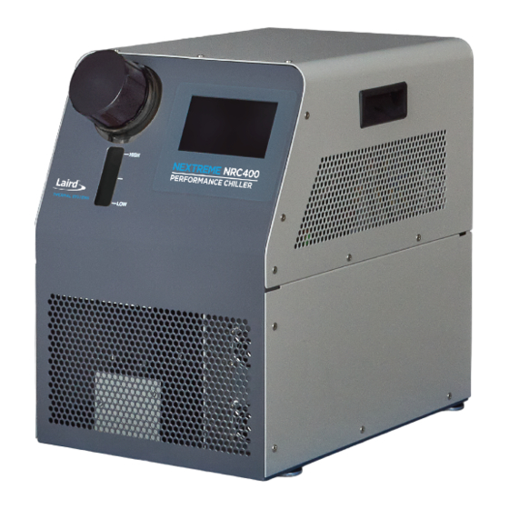
2. Introduction Nextreme NRC400 is a new generation recirculating chiller designed for precise temperature control of analytical instrumentation, industrial lasers and imaging. The NRC400 is a thermoelectric- based recirculating chiller with few moving parts offering solid-state construction and high reliability. It is also environmentally friendly as no hazardous refrigerants are used. -
Page 7: Safety Precautions
3. Safety Precautions This section provides an overview of all the important safety aspects for optimal protection of personnel as well as safe and trouble-free operation of the equipment. The operating manual and warning instructions specified herein should be reviewed completely by all personnel prior to operating the unit. -
Page 8: Guidelines Regarding Electrical Equipment
High Temperature Limit on Coolant Return - The maximum allowable coolant return (inlet) is 50°C. It is the responsibility of the customer to ensure that this limit is not exceeded. Laird Thermal Systems recommends a thermal shutoff be used in conjunction with the equipment being connected to the Recirculating Chiller. -
Page 9: Safety And Signaling Equipment Included In The Unit
The activities listed Table 1 in may only be performed by personnel with specialized knowledge. Table 1: Activities and specialized knowledge Activities Qualifications Industrial technician or sufficiently instructed personnel who can work on Working on mechanical and / or the unit under the guidance of the manufacturer’s technical support or hydraulic installations installation instructions Working on electrical installations... -
Page 10: In Case Of Accidents
Figure 1: Guards 3.4 In Case of Accidents Should you or another person be injured when working with the unit, do the following: ▪ Stay calm ▪ Perform first aid ▪ Always call the company’s first aid personnel ▪ If necessary, call the applicable emergency number 3.5 Environmental Issues Environmentally conscious and anticipatory behavior of staff helps avoid environmentally hazardous events. -
Page 11: Model Number Description
4. Model Number Description NRC400-T0-00-PC2 Basic Cooling Electrical Pump Model No. Engine Configuration NRC400 400 Watts Air Cooled / Plastic, Centrifugal 115-230V~, 2.17-4.35 A, Thermoelectric Pump 1ph, 50/60Hz See Laird Thermal Systems Online Wizard Configurator for Manufacturer’s Part Number. www.lairdthermal.com... -
Page 12: Specifications
(ANSI / UL / CSA / IEC EN 61010-1 Edition 3) Nominal capacity rating is given at a 20°C (68°F) setpoint, 20°C (68°F) ambient temperature, sea level, and 60Hz operation. For ambient conditions outside this range, please contact Laird Thermal Systems. -
Page 13: Component Locations
6. Component Locations Figure 2: Isometric Views of Unit Figure 3 Front View Figure 4 Rear View... -
Page 14: Labels And Markings
7. Labels and Markings 1 – Coolant level low marking 2 – Coolant level high marking 3 – Laird serial number label 4 – Caution hazardous voltage label: This label indicates location on the unit on the unit where power connections need to be made by the user. -
Page 15: Transport, Packaging And Storage
8. Transport, Packaging and Storage 8.1 Safety WARNING Damage due to improper transportation Injuries to persons and significant damage to property can occur in the case of improper transportation. ▪ When unloading the packed unit on delivery, including in-house transport, proceed very carefully and obey the symbols and instructions on the packaging. -
Page 16: Packaging
Symbol Meaning Do not stack This symbol indicates that goods are sensitive to stacking Handle with care This symbol indicates that package must be handled with care Team lift This symbol indicates that two or more persons must be used for lifting as the package is heavy Keep Upright This symbol indicates the goods are sensitive to tilt... -
Page 17: Handling The Unit While In The Packaging
8.6 Handling the Unit While in the Packaging WARNING Danger due to lifting and carrying heavy loads Manual handling of the loads (lifting, pushing, and carrying) must be avoided. ▪ Unit weight – Refer to Specifications. ▪ Use only suitable means of transport (such as industrial truck or lift truck). WARNING Danger of injury due to tipping or falling loads Bruises. - Page 18 Disconnect Hoses. Procedure Pack the unit according to the transport conditions that can be expected. Laird advises to use original packaging, if available, or an equivalent packaging. 1. Mark the packaging with the appropriate symbols. Refer to Symbols on the Packaging.
-
Page 19: Installation Requirements
9. Installation Requirements 1. Minimum Clearance from obstructions is required as shown to ensure that air intake and air discharge is not blocked as this could affect cooling capacity. Figure 6: Minimum Clearance required for Unit Installation 2. The location must be level 3. -
Page 20: Installation Procedure
Installation Procedure 10.1 Connect Hoses NOTE Risk of damage by using improper or faulty coolant hoses This may lead to damage to persons, damage to property, or corrosion damage. ▪ When choosing coolant hoses pay attention to burst pressure and compatibility with coolant. ▪... -
Page 21: Disconnect Hoses
10.2 Disconnect Hoses The coolant hoses are connected to the unit at the coolant inlet and coolant outlet connections, labeled with respective symbols. O TL T I L T Figure 8 Disconnecting Hoses Requirements ▪ Unit prepared for maintenance. Refer to Preparing the Unit for Maintenance. -
Page 22: Connecting Power
It is the user’s responsibility to assure a proper ground connection is provided. • Power Cord with C13 connector (not supplied by Laird Thermal Systems) • Use cable rated for 20A 250V with IEC320-C13 receptacle. The customer... - Page 23 Suggested Contaminant Limits: Organics Algae, Bacteria, etc. Inorganic Chemicals Calcium <10 Chloride <25 Copper <1.0 Iron <0.2 Lead Magnesium <5 Manganese <0.05 Nitrates \ Nitrites <10 Potassium <2 Silicate <5 Sodium <4 Sulfate <25 Hardness <1 Total Dissolved Solids <25 Other Parameters 6.8.
- Page 24 Plumbing & Refrigeration Diagram Figure 10: Plumbing and Refrigeration Diagram...
-
Page 25: Performance Graphs
Performance Graphs 11.1 Thermal Performance NRC400-T0-00-PC2 Cooling Capacity - Boost Mode ON 1 L/min Fluid Flow 100% Water (20°C Ambient Air) 70/30 Water-Glycol (20°C Ambient Air) 100% Water (30°C Ambient Air) 70/30 Water-Glycol (30°C Ambient Air) 100% Water (40°C Ambient Air) 70/30 Water-Glycol (40°C Ambient Air) 10.0... - Page 26 NRC400-T0-00-PC2 ΔT (Inlet-Outlet) Fluid Temperature Max System Cooling at 20°C Ambient Air 1 L/min Fluid Flow. 12.00 10.00 100% Water 8.00 ρ=997.2 kg/m3 Cp=4180.1 J/kg.K 6.00 70/30 Water-Glycol ρ=1048 kg/m3 4.00 Cp=3776.5 J/kg.K 2.00 0.00 10.0 15.0 20.0 25.0 30.0 35.0 40.0 Fluid Temperature Setpoint (°C)
-
Page 27: Pump Performance
11.2 Pump Performance Figure 14: Pump Performance with Cooling Fluids: Water & 30% EG/W NRC 400-T0-00-PC2... -
Page 28: Chiller Dimensions
Chiller Dimensions Figure 15: NRC400 Chiller Overall Dimensions... -
Page 29: Controller Display Panel Functions
Controller Display Panel Functions 13.1 Startup Screen When the unit is first powered on, the touch panel shows this screen for 10 seconds. Figure 16: Start-up Screen 13.2 Main Screen Figure 17: Main Menu Buttons Description Main Menu is selected Information Menu is selected Alarm menu is selected Settings menu is selected... -
Page 30: Running The Pump
Setpoint increments/decrements in 1.0 Increase setpoint by selected increment level Decrease setpoint by selected decrement level Stores set point in flash memory 13.2.1 Running the Pump The pump can be switched on by pressing the PUMP button on screen. The box will turn from grey to green which indicates that the pump is on. -
Page 31: Sleep Screen
13.3 Sleep Screen Touch panel goes to sleep when the screen has been inactive for 3 minutes and shows coolant supply temperature. The system does not go to sleep screen when the information screen is being displayed or when the unit is not running. Figure 20: Sleep Screen 13.4 Information Screen Figure 21: Information Screen... -
Page 32: Alarms Display Screen
Information Description Temperature This is the Supply Temperature from the chiller to the application Temperature setpoint This is the Temperature Setpoint set by User in the Main Menu Offset This is the Setpoint Offset set by the User in the Settings Menu 13.5 Alarms Display Screen If the system is not in an alarm condition, then the alarms tab doesn’t show any alarm. -
Page 33: Settings Screen
Figure 24: Acknowledging Alarms Buttons Description Alarm has been set Amber alarm Amber alarm Selected Red Alarm Red Alarm Selected Red alarms are used to indicate an abnormal system condition and is usually associated with the shutdown of a component or the whole system. There is an audible alarm for this condition and requires an action from the customer for the system to restart. -
Page 34: Boost Mode
percentages. Note that selecting the correct coolant is the responsibility of the customer and should match what is filled in the system by the customer. Selecting the wrong coolant may cause damage to the equipment. Water: 10°C to 40°C 10% Ethylene Glycol: 5°C to 40°C 20% Ethylene Glycol: 0°C to 40°C 30% Ethylene Glycol: -5°C to 40°C Figure 26: Choosing the Coolant... - Page 35 Alarms such as Low Temperature Δ and High Temperature Δ can be set in the Setting Menu Each Alarm can be turned ON or OFF as required and the value can be changed by clicking on the number. Low temp delta This alarm is to alert the customer if the coolant supply temperature doesn’t come within this specified deltaT from below the set point in a set amount of time.
-
Page 36: Setting Offset
13.7 Setting Offset Figure 31: Setting Menu Setting Offset This setting allows you to offset the displayed temperature from the measured temperature. 14. Troubleshooting For troubleshooting, use the following: ▪ Alarm status screen ▪ Wiring diagram ▪ Plumbing Diagram ▪ Troubleshooting table (below) Issue Possible Cause... - Page 37 Issue Possible Cause Corrective Measures Clearance By No flow in cooling circuit Check system for blockage or lack of fluid Operator Fan does not rotate Check to determine if the fan is rotating. Operator Ambient air temperature too Operate unit within allowable ambient Operator high temperature range.
-
Page 38: Alarms
15. Alarms *- Red: Critical with Stop, Amber: Notify, Green: Status Alarm Criticality Alarm Description Cause Effect Action Required/ Troubleshooting Low fluid level Coolant fluid level is Possible leak in the Entire system Check to see if the coolant level is at low. - Page 39 Alarm Criticality Alarm Description Cause Effect Action Required/ Troubleshooting High TEM Controller checks if the Heat load is too Entire system Check to see if the heat load is too Current TEM current exceeds high, or TEM is not stops running high.
-
Page 40: Communications Interface
16. Communications Interface 16.1 Instructions for Setup RS232 serial communications are available. They are accessible via the DB-9 connectors on the rear of the chiller. Refer Inadmissible Operating Conditions to avoid any safety hazards. A Terminal Emulator or other comparable device will need to be connected to the DB-9 to allow command to be entered. -
Page 41: System Maintenance And Service
17. System Maintenance and Service Diligent maintenance is the prime factor for assuring an error-free and efficient operation of the unit. All the maintenance tasks contained in this chapter must be performed according to the maintenance intervals. 17.1 Safety All safety and warning instructions must be reviewed completely by all personnel prior to maintenance work of the unit. -
Page 42: Maintenance Schedule
Environmental Issues NOTE Danger to the environment due to improper handling Environmentally conscious and anticipatory behavior of staff avoids environmentally hazardous impacts. The following principles apply for environmentally conscious behavior: ▪ Environmentally hazardous substances must not get into the soil or into the drains. They should be kept in appropriate containers. -
Page 43: Verification Of Safe State After Maintenance
▪ Terminate the cooling operation. ▪ Let the unit and its coolant cool down to the ambient temperature. ▪ Switch off the unit. ▪ Disconnect the unit from mains by pulling the mains plug. ▪ Secure the unit against being switched on again. ▪... -
Page 44: Draining Procedure
17.5 Draining Procedure NOTE Risk of Damage to the pump When the coolant level in the coolant tank is too low and if it runs the pump dry, the pump can be damaged or destroyed. ▪ Avoid running the pump dry to prevent damage Requirements ▪... - Page 45 ▪ If the fins of the heat exchanger are not in a suitable condition, the unit must only be used again once the damage has been rectified. Requirements ▪ Unit prepared for maintenance. Refer to Preparing the Unit for Maintenance. Required Tools and Materials ▪...
-
Page 46: Spare Parts
18. Spare Parts NRC400 (385901-002) Name Part No. Pump 387008261-SP 157005314-SP Tank Cap 387002004-SP Temp Sensor 387005808-SP... -
Page 47: Decommissioning And Disposal
Final decommissioning or disposal of the unit must be performed in accordance with the regulations of the country of use. Contact Laird Thermal Systems to return end-of-life units through the official website at https://www.lairdthermal.com/contact or contact a company specializing in the disposal and recycling of equipment. -
Page 48: Return Of The Unit To Laird
20.5 Return of the Unit to Laird Declaration of decontamination Before re-shipment of the unit a declaration of decontamination must be sent to Laird Thermal Systems. -
Page 49: Return Procedure
RMA# on the box. Consignor shall pay freight charges on all returns. This product is made by Laird Thermal Systems Shenzhen Limited. Address: Room 201, Dejin industrial park, No 34, Fuyuan 1 Road, Heping Community, Fuhai street, Baoan district, Shenzhen City, Guangdong Province, PRC. -
Page 50: List Of Figures
21. List of figures Figure 1: Guards ..........................10 Figure 2: Isometric Views of Unit ......................13 Figure 3 Front View Figure 4 Rear View ............ 13 Figure 5: Marking on Unit ........................14 Figure 6: Minimum Clearance required for Unit Installation ..............19 Figure 7 Connecting Hoses.........................
Need help?
Do you have a question about the Nextreme NRC400 and is the answer not in the manual?
Questions and answers