Table of Contents
Advertisement
Quick Links
Advertisement
Table of Contents

Subscribe to Our Youtube Channel
Related Manuals for LiteOn AP900Ci

Summary of Contents for LiteOn AP900Ci
- Page 1 Installation manual Cruise Control Speed limiter RPM limiter AP900Ci...
- Page 2 This installation manual is written for professional installers with knowledge and experience with modern vehicle engineering and vehicle-electronics. The AP900Ci is a modular product that has been designed and produced to the highest quality standards of the automotive industry. The AP900Ci can provide the following functions:...
-
Page 3: Table Of Contents
CONTENTS: Chapter Name Page Introduction..........................4 Safety directions ……………………………………………………………..5 Kit content…………………………………………………………………..6 Tools required.......................... 6 ........................7 Wiring diagram Installation and connections....................8 Location module ........................8 Connections..........................9/10 Set-up ………………………………………………………………………... 10 Activation procedure......................11 Throttle calibration …………………………………………………………..Speed-signal calibration......................13 Adjusting engage timing ....................... -
Page 4: Introduction
The AP900Ci is usually provided by your supplier with the vehicle-specific data pre-programmed. If you install AP900Ci and SL900Ci on a regularly base, it’s also possible to program the module yourself for the desired vehicle, you require a USB programming cable (LTK-0900090). -
Page 5: Safety Directions
SAFETY DIRECTIONS The AP900Ci is designed to function as a Cruise Control, Speed Limiter or RPM limiter. The installer must have sufficient knowledge and experience with modern vehicle-electronics. Incorrect and/or substandard installation, connection, adjustments and/or diagnostics of the vehicle and/or Cruise Control may indirectly affect road safety. -
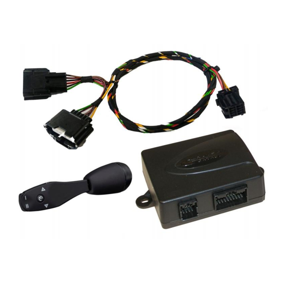
Page 6: Kit Content
Kit Content Item Part No. Description Picture A10.2014940 Electronic module 190.5000400 Main harness LTK.1400150 1 Hardware kit 190-5002*** Throttle connection cable Users- Manual Installation- Manual TOOLS REQUIRED For connections where a connector does not apply, it is strongly recommended to solder and isolate with volcanizing tape to ensure a reliable installation. -
Page 7: Wiring Diagram
WIRING DIAGRAM... -
Page 8: Installation And Connections
INSTALLATION AND CONNECTIONS 6.1 LOCATION MODULE Always place the module in the passenger compartment of the vehicle. Avoid locations with excessive heat, moisture and power lines. Usual mounting areas are under the dashboard, behind the glove compartment or behind the A-style panel at the driver side or passenger side. Never place the module in the engine compartment. -
Page 9: Connections
6.2 WIRING CONNECTIONS When the module is positioned, it is possible to route and connect the harness. If necessary, use a digital multimeter to determine the correct connection points. See also the wiring diagram at page 7. Follow the connection data as stated in the vehicle-specific manual and/or the pop-up screen that is displayed after programming the module via the PC. -
Page 10: Set-Up
Purple wire Clutch (if necessary) If the clutch signal is not present on the CAN-bus, the purple wire must be connected. This is also visible in the programming tool, at the CAN-baut is no at the Clutch / Neutral. The purple wire can be connected in 2 ways: 1. -
Page 11: Activation Procedure
7.1 ACTIVATION PROCEDURE From a safety point of view, the Cruise Control functions are blocked from factory. The software in the AP900Ci must be verified with the vehicle CAN-data. Run the activation procedure to activate the Cruise Control functions. 4x low... -
Page 12: Throttle Calibration
7.2 THROTTLE CALIBRATION 2x low 4x high green press 4x to start switch on the press and hold the turn the ignition off the setup Cruise Control brake within 45 and on again seconds 1x low 1x high 1x high press 1x press and hold the release the brake... -
Page 13: Speed-Signal Calibration
SPEED-SIGNAL CALIBRATION In exceptional cases, it may be necessary to calibrate the speed-signal. 2x low 4x high green press and hold turn the ignition off switch on the press 4x the brake within and on and start the Cruise Control start the setup 45 seconds engine immediately... -
Page 14: Adjusting Engage Timing
ADJUSTING ENGAGE TIMING (Cruise Control process adjustment INIT) 4x high 2x low green turn the ignition off switch on the press and hold the press 4x and on and start the Cruise Control brake within 45 start the setup engine immediately seconds orange 3x low... -
Page 15: Adjusting Speed Sensitivity
7.5 ADJUSTING SPEED SENSITIVITY (Cruise Control process adjustment GAIN) 4x high 2x low green press 4x turn the ignition off switch on the press and hold the and on and start the start the setup Cruise Control brake in 45 engine immediately seconds 4x low... -
Page 16: Diagnosis 1
DIAGNOSE The Cruise Control has an integrated diagnostic function. The diagnostic includes 2 steps to test all connections and features of the Cruise Control without using a laptop. first of all check the installation. Pull the handbrake and turn the gear into neutral. If something is not functioning, reference shall be made to a fault table. -
Page 17: Diagnosis 2 Throttle, Speed-Signal Test
8.2 Diagnosis 2 (accelerator-pedal, speed-signal test) pulsating 1 x low green turn off the ignition press and hold start the engine release the switch on the Cruise Control pulsating pulsating orange orange calibrate go to table 2 throttle RPM revs up. press and hold press until... - Page 18 8.3 Table 1 Diagnosis 1x low 1x low make sure the +15 switched 12V go to table 2 go to table 2 power supply is press 1x press 1x correctly continue with connected table 2 diagnosis 8.4 Table 2 diagnosis 1x low green orange...
-
Page 19: Error Codes
8.6 Error codes The Cruise Control is equipped with an error code generator in case as the Cruise Control switches off or does not switches on for an abnormal reason. The error code is indicated with beeps: : Tone Discription control function is pressed for more than 20 seconds acceleration speed is more then 9 kph per second speed drops below 33 kph... - Page 20 The Cruise Control falls far back in Engage timing setting is too low (INIT) speed after engaging The car accelerates when engaging Engage timing setting is too high (INIT) the Cruise Control The car is very nervous when the The speed sensitivity is set too high (GAIN) Cruise Control is engaged The car fluctuates in speed when The speed sensitivity is set too low (GAIN)
Need help?
Do you have a question about the AP900Ci and is the answer not in the manual?
Questions and answers