Table of Contents
Advertisement
Quick Links
BAT-3105
Club Car Precedent 2004-2008.5
Lithium Battery Pack Installation Kit
(4) 12V LiFePo4 Batteries
INSTALLATION INSTRUCTIONS
Caution: Please read through the instructions carefully. Before starting this project, remove the system's positive (+) and negative (-) connections
from the battery pack. Look behind each drill location BEFORE YOU DRILL. (i.e. drilling into a wiring harness, battery etc.). Installer is responsible
for damage if instructions are not followed properly.
Batteries: This kit is designed to replace (4) 12V lead acid batteries in the Club Car Precedent, 2004-08.5. Different battery mounting components
may be required if the cart has (6) 8V batteries.
On Board Computer (OBC): The OBC cannot be used with lithium batteries and must be bypassed in order to use this kit. The CGR-123 Bypass
Kit (sold separately) can be used to bypass the OBC.
Charger Warning: **DO NOT USE LEAD ACID GOLF CAR CHARGERS**. Only use the approved charger(s) recommended in the battery
manufacturer's Operator's Manual. Affix the supplied Caution Label just above the charger port to ensure only approved LiFePo4 lithium chargers
can be used.
Revision B-072423
Advertisement
Table of Contents

Related Manuals for RHOX BAT-3105

Summary of Contents for RHOX BAT-3105
- Page 1 BAT-3105 Club Car Precedent 2004-2008.5 Lithium Battery Pack Installation Kit (4) 12V LiFePo4 Batteries INSTALLATION INSTRUCTIONS Caution: Please read through the instructions carefully. Before starting this project, remove the system’s positive (+) and negative (-) connections from the battery pack. Look behind each drill location BEFORE YOU DRILL. (i.e. drilling into a wiring harness, battery etc.). Installer is responsible for damage if instructions are not followed properly.
-
Page 2: Table Of Contents
Table of Contents . . . . . . . . . . . . . . . . . . . . . . . . . . . . . . . . . . . . . . . . . . . . . . . . . . . . . . . . . . . . . . . . . . . . . . . . . . . . . . . . . 2 Tools Needed for Installation . -
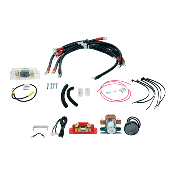
Page 3: Contents Of Kit
Contents of Kit BATTERY CABLES (2 AWG) Qty . Length From Terminal and Terminal and Heat Shrink Color Heat Shrink Color 6” -12V on Battery 5/16” Ring SOC Shunt (B-) 3/8” Ring 9” Solenoid (+) OUT 5/16” Ring Controller (B+) 5/16”... -
Page 4: Remove Lead Acid Batteries And Clean Battery Compartment
Remove Lead Acid Batteries and Clean Battery Compartment Turn Key OFF . Engage parking brake . Place Tow/Run Switch in Tow . With the cart in Tow, use a voltage meter to identify which terminal on the Tow/Run Switch is OFF . This wire is normally pink in an OE configuration. - Page 5 Carefully loosen (1) screw on either of the (B+) terminals on the SOC Shunt using a jeweler’s screwdriver . Use a pick to open the hole by sliding the tab out of the way, as shown . Insert (1) stripped end of the 34”, 20 AWG Pink Wire into the (B+) terminal that was opened in Step 2 and tighten the screw . NOTE: Please review the manufacturer’s SOC Instruction Manual for details .
-
Page 6: Install Anl Fuse Holder
11 . Disconnect the 6” 2AWG battery cable from the battery and remove the battery . 12 . Following the diagram and the steps below, connect the remaining wires to the “P-” terminal on the SOC shunt . NOTE: Multiple wires may be attached to the “P-” terminal and it may look like the photo to the right . -
Page 7: Install Solenoid
Locate (1) 16” 2AWG Battery Cable included in the kit . Loosely install one side of the ANL Fuse Holder cable to the ANL fuse holder . Connect the opposite side to the positive (+) terminal on Mounting Location the 12V battery . Locate an area on the rear wall of the battery compartment to mount the fuse holder . -
Page 8: Install Batteries
Install Batteries Place the remaining batteries as shown in the diagram below, paying attention to where the positive and negative terminals are positioned . ANL Fuse Holder (+36V) (+24V) 12” Cable 12” Cable (+48V) (+12V) OEM Charger Receptacle (B-) from SOC Shunt Front of Cart Install both OEM battery hold down plates using the (2) Original Hold Down Rods, Nuts and Flat Washers along with (2) Included PVC Spacers . -
Page 9: Install State Of Charge (Soc) Meter, Dash Mount
Install State of Charge (SOC) Meter, Dash Mount Find a location on the dash to mount the SOC meter . Mount the meter and connect the wire harness to the meter per the instructions included with the SOC meter . Run the opposite end of the wiring harness under the cart and towards the SOC shunt within the battery compartment . -
Page 10: Optional: Install Sb-50 Charger Plug (Sold Separately)
Use a digital voltmeter to verify all connections and the total voltage of the pack . Check the charger receptacle’s voltages and the battery pack’s main negative (-) to the positive (+) 48V terminal for the correct polarity and voltage . The reading should be above +48V . Lithium batteries will generally read +52V static and not fully charged . Place Tow/Run Switch in RUN . -
Page 11: Notes On On-Board Computer (Obc)
Notes on On-Board Computer (OBC) The OBC was bypassed and removed in the photos shown below . The battery charger for lithium batteries is NOT controlled by the OBC so the OBC can be bypassed and removed . The OBC would normally charge the batteries and control the Tow/Run switch . The procedure described moved the red/pink wire to the positive (+) 48V battery terminal along with the positive (+) cable from the solenoid . -
Page 12: Notes
Notes PAGE 12...
Need help?
Do you have a question about the BAT-3105 and is the answer not in the manual?
Questions and answers