Table of Contents
Advertisement
Quick Links
Advertisement
Table of Contents

Subscribe to Our Youtube Channel
Related Manuals for LS ELECTRIC Xmotion L7S Series


Summary of Contents for LS ELECTRIC Xmotion L7S Series
- Page 1 Xmotion L7S Series...
- Page 3 The reproduction of part or all of the contents of this manual in any form, by any means or for any purpose is strictly prohibited without the explicit written consent of LS ELECTRIC. LS ELECTRIC retains all patents, trademarks, copyrights and other intellectual property rights to the material in this manual.
-
Page 4: Electric Safety Precautions
Safety Precautions Safety Precautions Safety precautions are categorized as either Danger or Cautions, depending on the severity of the precaution. Precautions Meaning Failure to comply with these guidelines may cause serious injury or death. Danger Failure to comply with these guidelines may cause personal injury or property Caution damage. -
Page 5: Installation Precautions
Safety Precautions Installation Precautions Store and operate this product under the following environmental conditions. Conditions Environment Servo Drive Servo Motor Ambient 0∼50[℃] 0~40[℃] temperature Storage temp. -20∼65[℃] -10~60[℃] Ambient 80% RH or less (no condensation) humidity 90% RH or less (no condensation) Storage 90% RH or less (no condensation) humidity... -
Page 6: Wiring Precautions
Safety Precautions Wiring Precautions Caution Be sure to use the input power of the servo drive after checking the product. L7SA□□□A/B: AC 200[V]~230[V], L7SB□□□B: AC 380[V]~480[V] Be sure to connect the ground terminal of the servo drive to the ground terminal. ... -
Page 7: Usage Precautions
Safety Precautions Usage Precautions Caution Install an emergency cut-off switch which immediately stops operation in an emergency. Reset the alarm when the servo is off. Be warned that the system restarts immediately if the alarm is reset while the servo is on. ... - Page 8 Safety Precautions EEPROM Lifespan Caution The EEPROM is rewritable up to 1 million times for the purpose of recording parameter settings and other information. The servo drive may malfunction if the total number of the following tasks exceeds 1 million, depending on the lifespan of the EEPROM. ...
- Page 9 Table of Contents Introduction ........i Safety Precautions ......ii 1. Product configuration and signal description1-1 1.1 Product configuration ............. 1-1 Product Verification ........................1-1 1.1.1 Part Names ..........................1-3 1.1.2 1.2 System Configuration ............1-15 Overview ............................ 1-15 1.2.1 CN1 connector overall wiring diagram ................
- Page 10 L7 drive block diagram [L7SA150B, L7SB150B] ............4-14 4.2.3 Power circuit Electrical Components ................4-15 4.2.4 4.3 Connection Example with PLC device ......... 4-27 LS ELECTRIC .......................... 4-27 4.3.1 4.4 Timing diagram ..............4-34 Timing diagram when power is turned on ..............4-34 4.4.1 Timing chart when an alarm occurs .................
- Page 11 DS cable ......................4-42 4.7.2 APCS-E ES cable ......................4-43 4.7.3 APCS-E 4.8 Multi Encoder Signaling unit (CN2) wiring ......4-44 CS1 cable ......................4-44 4.8.1 APCS-E DS1 cable ......................4-44 4.8.2 APCS-E ES1 cable ......................4-45 4.8.3 APCS-E 4.9 Absolute encoder data transmission ........4-46 Absolute encoder data transmission ................
- Page 12 System parameter setting ....................5-97 5.4.1 Control parameter setting ....................5-100 5.4.2 Analog input/output parameter setting ................ 5-104 5.4.3 I/O parameter setting ......................5-105 5.4.4 Speed operation parameter setting ................5-108 5.4.5 Position operation parameter setting ................5-109 5.4.6 5.5 List of alarms and warnings ..........5-111 Summary display list of servo alarm status ...............
- Page 13 7.1 Overview and Communication spec........7-1 Overview ............................7-1 7.1.1 Communication specification and cable connection diagram ........7-2 7.1.2 7.2 Communication protocol basic structure ........ 7-3 Sending and receiving packet structure ................7-3 7.2.1 Protocol Command Code ....................... 7-5 7.2.2 7.3 L7 Servo Drive Communication Address Table ....
-
Page 15: Product Configuration
1. Product configuration and signal description Product configuration and signal description Product configuration 1.1.1 Product Verification 1. Check the name tag to verify that the product received matches the model ordered Does the servo driver's name plate match? Does the servo motor's name plate match? 2. - Page 16 1. Product configuration and signal description Servo motor product type APM C – F E P 30 A M K 1 Input voltage Rated speed Option spec. SERVO MOTOR Blank : 200Vac Blank : None : 3000 [rpm] : Oil Seal : 400Vac : 2000 [rpm] : Brake...
-
Page 17: Part Names
1. Product configuration and signal description 1.1.2 Part Names Servo Motor 80 Flange or below Motor Power Motor Cable Encoder Connector Connector Encoder Cable Encoder Cover Shaft Frame Flange Housing Bearing Cap •80 Flange or less (L series) Encoder connector Power connector Shaft Flange... - Page 18 1. Product configuration and signal description Servo Drive L7SA 001□, L7SA 002□, L7SA 004□ Display Operation keys CN5: USB connector Main power connector (L1, L2, L3) CN4: RS-422 communication DC reactor connector connector (PO, PI) Short circuit when not used CN3: RS-422 communication connector...
- Page 19 1. Product configuration and signal description L7SA 008□, L7SA 010□ Display Operation keys CN5: USB connector Main power connector (L1, L2, L3) CN4: RS-422 communication DC reactor connector connector (PO, PI) Short circuit when not used CN3: RS-422 communication connector Regenerative resistor connector (B+, B, BI)
- Page 20 1. Product configuration and signal description L7SA 020□, L7SA 035□ Display Operation keys CN5: Main power connector USB connector (L1, L2, L3) CN4: DC reactor connector RS-422 communication (PO, PI) connector Short circuit when not used CN3: RS-422 communication connector Regenerative resistor connector (B+, B, BI)
- Page 21 1. Product configuration and signal description L7SA 050□ Display Operation keys CN5: USB Connector CN4: RS-422 Communication connector CN3: RS-422 Communication connector CN1: Control signal connector CN2: Encoder signal connector Not used(N) DC reactor connector (PO, PI) Short circuit when not used Control power connector (C1, C2) PE: Protective earth...
- Page 22 1. Product configuration and signal description L7SA 075B Display Operation keys Mode, Up, Down, Set) CN5: USB connector CN4: RS-422 communication connector CN3: RS-422 communication connector CN1: Control signal connector CN2: Encoder signal connector DC reactor connector (PO, PI) Short circuit when not used *DO NOT connect Control power connector...
- Page 23 1. Product configuration and signal description L7SA 150B Display Operation keys (Mode, Up, Down, Set) CN5: USB Connector CN4: RS-422 Communication connector CN3: RS-422 Communication connector CN1: Control signal connector CN2: Encoder signal connector DC reactor connector (PO, PI) Short circuit when not used Control power connector (C1, C2)
- Page 24 1. Product configuration and signal description L7SB 010B Operation keys (Mode, Up, Down, Set) Display Main power connector CN5: (L1, L2, L3) USB connector * Not used(N) CN4: RS-422 communication connector DC reactor connectors (PO, PI) CN3: Short circuit when not used RS-422 communication connector Regenerative resistor...
- Page 25 1. Product configuration and signal description L7SB 020B, L7SAB035B Operation keys (Mode, Up, Down, Set) Display Main power connector (L1, L2, L3) CN5: USB connector Not used (N) CN4: DC reactor connectors RS-422 communication connector (PO, PI) Short circuit when not used CN3: RS-422 communication connector...
- Page 26 1. Product configuration and signal description L7SB 050B Display Operation keys (Mode, Up, Down, Set) CN5: USB connector CN4: RS-422 communication connector CN3: RS-422 communication connector CN1: Control signal connector CN2: Encoder signal connector * Not used(N) DC reactor connector (PO, PI) Short circuit when not used Control power connector...
- Page 27 1. Product configuration and signal description L7SB 075B Display Operation keys (Mode, Up, Down, Set) CN5: USB connector CN4: RS-422 communication connector CN3: RS-422 communication connector CN1: Control signal connector CN2: Encoder signal connector Main power connector (L1, L2, L3) Motor power connector(U, V, W) * Not used (N)
- Page 28 1. Product configuration and signal description L7SB 150B Display Operation keys (Mode, Up, Down, Set) CN5: USB connector CN4: RS-422 communication connector CN3: RS-422 communication connector CN1:Control signal connector CN2: Encoder signal connector Control power connector (C1, C2) DC reactor connector (PO, PI) Short circuit when not used Motor power connector...
-
Page 29: System Configuration
1. Product configuration and signal description System Configuration 1.2.1 Overview The L7 servo system can be configured and used in various ways according to the interface method with the host controller. (1) Position operation system As a method of driving the servo with a pulse command, the position of the servo motor is operated by converting the command pulse according to the constant feed unit. -
Page 30: Operation Mode
1. Product configuration and signal description (3) Torque operation system As a way to drive servo with torque command, torque command by analog voltage is used. Host Controller Servo Drive Servo Motor Torque Command Change Position Torque Torque Current Motor Torque Controller Controller... - Page 31 1. Product configuration and signal description 1.2.2 CN1 connector overall wiring diagram Digital output Digital input Note1) DC 24V ALARM+ +24V IN (DO1) ALARM- 3.3kΩ Note)1 (DIA) STOP READY+ (DI9) (DO2) READY- (DI8) CWLIM (DI7) CCWLIM ZSPD (DI6) (DO3) BRAKE (DI5) ALMRST (DO4)
- Page 32 1. Product configuration and signal description 1.2.3 Position Operation Mode Wiring Example Digital Input Digital Output Note 1) (DO1) DC 24V ALARM+ +24V IN 3.3kΩ ALARM- Note1) (DO2) (DIA) STOP READY+ (DI9) READY- (DI8) CWLIM (DO3) ZSPD (DI7) CCWLIM (DO4) BRAKE (DI6) (DO5)
- Page 33 1. Product configuration and signal description 1.2.4 Speed Operation Mode Wiring Example Digital output Digital input Note1) DC 24V ALARM+ +24V IN (DO1) ALARM- 3.3kΩ Note1) (DIA) STOP READY+ (DI9) (DO2) READY- (DI8) CWLIM (DI7) CCWLIM ZSPD (DI6) (DO3) BRAKE (DI5) ALMRST (DO4)
- Page 34 1. Product configuration and signal description 1.2.5 Torque Operation Mode Wiring Example Digital output Digital input Note1) DC 24V ALARM+ +24V IN (DO1) ALARM- 3.3kΩ Note1) (DI9) STOP READY+ (DI8) (DO2) READY- (DI7) CWLIM (DI6) CCWLIM ZSPD (DI5) (DO3) BRAKE (DI4) ALMRST (DO4)
- Page 35 1. Product configuration and signal description 1.2.6 Speed/Position Operation Mode Wiring Example Digital output Digital input Note1) DC 24V ALARM+ +24V IN (DO1) ALARM- 3.3kΩ Note1) (DIA) STOP READY+ (DI9) (DO2) READY- (DI8) CWLIM (DI7) CCWLIM ZSPD Note3) (DI6) (DO3) MODE INSPD (DI5)
- Page 36 1. Product configuration and signal description 1.2.7 Speed/Torque Operation Mode Wiring Example Digital Digital input output Note1) DC 24V ALARM+ +24V IN (DO1) ALARM- 3.3kΩ Note1) (DIA) STOP READY+ (DI9) (DO2) READY- (DI8) CWLIM (DI7) CCWLIM TLMT Note3) (DI6) (DO3) MODE VLMT (DI5)
- Page 37 1. Product configuration and signal description 1.2.8 Position/Torque Operation Mode Wiring Example Digital output Digital input Note1) DC 24V ALARM+ +24V IN (DO1) ALARM- 3.3kΩ Note1) (DIA) STOP READY+ (DI9) (DO2) READY- (DI8) CWLIM (DI7) CCWLIM VLMT Not3) (DI6) (DO3) MODE TLMT (DI5)
-
Page 38: Signal Description
1. Product configuration and signal description Signal description 1.3.1 Digital input contact signal Application table by operation mode Initial Spee Spee Positi shipment Name Contents Positi Spee Torqu d/Pos d/Tor on/To Pin No. ition rque +24V IN +24[V] power Input SVON Servo On SPD1... - Page 39 1. Product configuration and signal description 1.3.3 Digital output contact signal Application table by operation mode Initial Posit Spee Spee shipment Name Content Posit Spee Torq ion/T d/Po d/Tor Pin No. orqu sition Alarm group contact ALO0 output 1 Alarm group contact ALO1 output 2 Alarm group contact...
- Page 40 1. Product configuration and signal description 1.3.5 Pulse string input signal Line driver(5V) Application table by operation mode Speed/ Positio Name Content Positio Speed/ Speed Torque Positio n/Torqu Torque F+ pulse input F- pulse input R+ pulse input R- pulse input PULC No use ...
-
Page 41: Product Specification
2. Product specification Product specification Servo Motor ■ Heat Sink Spec. Classification Size(mm) Classification AP04 250x250x6 AP06 250x250x6 AP08 250x250x12 Aluminum AP13 350x350x20 AP18 550x550x30 AP22 650x650x35 Note1) In the case of product specifications, it is the data measured after applying the heat sink. ※... -
Page 42: Product Features
2. Product specification 2.1.1 Product Features ■ [200V] SAR3A SAR5A SA01A SA015A Servo Motor Type (APM- Applicable Drive (L7SAxxx□) L7SA001□ L7SA002□ [kW] 0.03 0.05 0.10 0.15 Rated output [N⋅m] 0.10 0.16 0.32 0.48 Rated torque 0.97 1.62 3.25 4.87 [kgf⋅cm] Maximum [N⋅m] 0.29... - Page 43 2. Product specification ■ [200V] (APM- SB01A SB02A SB04A Servo Motor Type (L7SAxxx□) L7SA002□ L7SA004□ Applicable Drive [kW] 0.10 0.20 0.40 Rated output [N⋅m] 0.32 0.64 1.27 Rated torque [kgf⋅cm] 3.25 6.49 12.99 [N⋅m] 0.96 1.91 3.82 Maximum instantaneous [kgf⋅cm] 9.74 19.48 38.96...
- Page 44 2. Product specification ■ [200V] (APM- SC04A SC06A SC08A SC10A Servo Motor Type (L7SAxxx□) L7SA004□ L7SA008□ L7SA010□ Applicable Drive [kW] Rated output [N⋅m] 1.27 1.91 2.55 3.19 Rated torque [kgf⋅cm] 12.99 19.49 25.98 32.48 [N⋅m] 3.82 5.73 7.64 9.56 Maximum instantaneous [kgf⋅cm] 38.96...
- Page 45 2. Product specification ■ [200V] (APM- SC03D SC05D SC06D SC07D Servo Motor Type (L7SAxxx□) L7SA004□ L7SA008□ Applicable Drive [kW] 0.30 0.45 0.55 0.65 Rated output [N⋅m] 1.43 2.15 2.63 3.10 Rated torque [kgf⋅cm] 14.61 21.92 26.79 31.66 [N⋅m] 4.30 6.45 7.88 9.31 Maximum...
- Page 46 2. Product specification ■ [200V] (APM- FALR5A FAL01A FAL015A FBL01A FBL02A FBL04A Servo Motor Type (L7SAxxx□) L7SA001B L7SA002B L7SA001B L7SA002B L7SA004B Applicable Drive [kW] 0.05 0.10 0.15 0.10 0.20 0.40 Rated output [N⋅m] 0.16 0.32 0.48 0.32 0.64 1.27 Rated torque [kgf⋅cm] 1.62 3.25...
- Page 47 2. Product specification ■ [200V] (APM- FCL04A FCL06A FCL08A FCL10A Servo Motor Type (L7SAxxx□) L7SA004B L7SA008B L7SA010B Applicable Drive [kW] 0.40 0.60 0.75 1.00 Rated output [N⋅m] 1.27 1.91 2.39 3.18 Rated torque [kgf⋅cm] 12.99 19.49 24.36 32.48 [N⋅m] 3.82 5.73 7.16 9.55...
- Page 48 2. Product specification ■ [200V] (APM- FCL03D FCL05D FCL06D FCL07D Servo Motor Type (L7SAxxx□) L7SA004B L7SA008B Applicable Drive [kW] 0.30 0.45 0.55 0.65 Rated output [N⋅m] 1.43 2.15 2.63 3.10 Rated torque [kgf⋅cm] 14.62 21.92 26.80 31.67 [N⋅m] 4.30 6.45 7.88 9.31 Maximum...
- Page 49 2. Product specification ■ [200V] (APM- HB01A HB02AA HB04A HE09A HE15A HE30A Servo Motor Type (L7SAxxx□) L7SA002A L7SA002A L7SA010A L7SA020A L7SA035A Applicable Drive [kW] Rated output [N⋅m] 0.32 0.64 1.27 2.86 4.77 9.55 Rated torque [kgf⋅cm] 3.25 6.49 12.99 29.23 48.72 97.43 [N⋅m]...
- Page 50 2. Product specification ■ [200V] (APM- FE09A FE15A FE22A FE30A Servo Motor Type (L7SAxxx□) L7SA010B L7SA020B L7SA035B Applicable Drive [kW] Rated output [N⋅m] 2.86 4.77 7.00 9.55 Rated torque [kgf⋅cm] 29.20 48.70 71.40 97.40 [N⋅m] 8.59 14.32 21.01 28.65 Maximum instantaneous [kgf⋅cm] 87.70...
- Page 51 2. Product specification ■ [200V] (APM- FE06D FE11D FE16D FE22D Servo Motor Type (L7SAxxx□) L7SA008B L7SA010B L7SA020B Applicable Drive [kW] Rated output [N⋅m] 2.86 5.25 7.63 10.5 Rated torque [kgf⋅cm] 29.2 53.60 77.90 107.10 [N⋅m] 8.59 15.75 22.92 31.51 Maximum instantaneous [kgf⋅cm] 87.70...
- Page 52 2. Product specification ■ [200V] (APM- FE05G FE09G FE13G FE17G Servo Motor Type (L7SAxxx□) L7SA008B L7SA010B L7SA020B Applicable Drive [kW] 0.45 0.85 Rated output [N⋅m] 2.86 5.41 8.27 10.82 Rated torque [kgf⋅cm] 29.22 55.19 84.41 110..38 [N⋅m] 8.59 16.23 24.82 32.46 Maximum instantaneous...
- Page 53 2. Product specification ■ [200V] (APM- FE03M FE06M FE09M FE12M Servo Motor Type (L7SAxxx□) L7SA004B L7SA008B L7SA010B L7SA020B Applicable Drive [kW] Rated output [N⋅m] 2.86 5.72 8.59 11.46 Rated torque [kgf⋅cm] 29.22 58.4 87.7 116.9 [N⋅m] 8.59 17.18 25.77 34.22 Maximum instantaneous [kgf⋅cm]...
- Page 54 2. Product specification ■ [200V] (APM- FF30A FF50A FF22D FF35D FF55D FF75D Servo Motor Type (L7SAxxx□) L7SA035B L7SA050B L7SA020B L7SA035B L7SA050B L7SA075B Applicable Drive [kW] Rated output [N⋅m] 9.55 15.91 10.50 16.70 26.25 35.81 Rated torque [kgf⋅cm] 97.40 162.30 107.10 170.40 267.80 365.40...
- Page 55 2. Product specification ■ [200V] (APM- FF20G FF30G FF44G FF60G FF75G Servo Motor Type (L7SAxxx□) L7SA020B L7SA035B L7SA050B L7SA075B Applicable Drive [kW] Rated output [N⋅m] 11.45 18.46 28.00 38.20 47.70 Rated torque [kgf⋅cm] 116.90 188.30 285.70 389.80 487.20 [N⋅m] 34.35 55.38 78.40 95.50...
- Page 56 2. Product specification ■ [200V] (APM- FF12M FF20M FF30M FF40M Servo Motor Type (L7SAxxx□) L7SA020B L7SA035B L7SA050B Applicable Drive [kW] Rated output [N⋅m] 11.46 19.09 28.64 42.02 Rated torque [kgf⋅cm] 116.9 194.8 292.2 428.7 [N⋅m] 34.38 57.29 85.94 105.05 Maximum instantaneous [kgf⋅cm] 350.70...
- Page 57 2. Product specification ■ [200V] (APM- FG22D FG35D FG55D FG75D FG110D Servo Motor Type (L7SAxxx□) L7SA020B L7SA035B L7SA050B L7SA750B L7SA150B Applicable Drive [kW] Rated output [N⋅m] 10.50 16.71 26.25 35.81 52.52 Rated torque [kgf⋅cm] 107.1 170.4 267.8 365.4 525.9 [N⋅m] 31.51 50.12 78.76...
- Page 58 2. Product specification ■ [200V] (APM- FG20G FG30G FG44G FG60G FG85G FG110G FG150G Servo Motor Type (L7SAxxx□) L7SA020B L7SA035B L7SA050B L7SA075B L7SA150B Applicable Drive [kW] Rated output [N⋅m] 11.50 18.50 28.00 38.2 54.11 69.99 95.45 Rated torque [kgf⋅cm] 116.9 188.4 285.8 389.7 552.1...
- Page 59 2. Product specification ■ [200V] (APM- FG12M FG20M FG30M FG44M FG60M Servo Motor Type (L7SAxxx□) L7SA020B L7SA020B L7SA020B L7SA075B Applicable Drive [kW] Rated output [N⋅m] 11.50 19.10 28.60 42.00 57.29 Rated torque [kgf⋅cm] 116.9 194.9 292.3 428.7 584.6 [N⋅m] 34.40 57.30 85.90 126.00...
- Page 60 2. Product specification ■ [400V] (APM- FEP09A FEP15A FEP22A FEP30A Servo Motor Type (L7SBxxxB) L7SB010B L7SB020B L7SB035B Applicable Drive [kW] Rated output [N⋅m] 2.86 4.77 7.00 9.55 Rated torque [kgf⋅cm] 29.23 48.72 71.46 97.44 [N⋅m] 8.59 14.32 21.01 28.65 Maximum instantaneous [kgf⋅cm] 87.7...
- Page 61 2. Product specification ■ [400V] (APM- FEP06D FEP11D FEP16D FEP22D Servo Motor Type (L7SBxxxB) L7SB010B L7SB020B Applicable Drive [kW] Rated output [N⋅m] 2.86 5.25 7.64 10.5 Rated torque [kgf⋅cm] 29.23 53.59 77.95 107.19 [N⋅m] 8.59 15.76 22.92 31.51 Maximum instantaneous [kgf⋅cm] 87.7 160.78...
- Page 62 2. Product specification ■ [400V] (APM- FEP05G FEP09G FEP13G FEP17G Servo Motor Type (L7SBxxxB) L7SB010B L7SB020B Applicable Drive [kW] 0.45 0.85 Rated output [N⋅m] 2.86 5.41 8.28 10.82 Rated torque [kgf⋅cm] 29.23 55.22 84.45 110.43 [N⋅m] 8.59 16.23 24.83 32.47 Maximum instantaneous [kgf⋅cm]...
- Page 63 2. Product specification ■ [400V] (APM- FEP03M FEP05M FEP09M FEP12M Servo Motor Type (L7SBxxxB) L7SB010B L7SB020B Applicable Drive [kW] Rated output [N⋅m] 2.86 5.73 8.59 11.46 Rated torque [kgf⋅cm] 29.23 58.47 87.70 116.93 [N⋅m] 8.59 17.19 25.78 34.38 Maximum instantaneous [kgf⋅cm] 87.70 175.40...
- Page 64 2. Product specification ■ [400V] (APM- FFP30A FFP50A FFP22D FFP35D FFP55D FFP75D Servo Motor Type (L7SBxxxB) L7SB035B L7SB075B L7SB020B L7SB035B L7SB050B L7SB075B Applicable Drive [kW] Rated output [N⋅m] 9.55 15.92 10.50 16.71 26.26 35.81 Rated torque [kgf⋅cm] 97.44 162.40 107.19 170.52 267.96 365.41...
- Page 65 2. Product specification ■ [400V] (APM- FFP20G FFP30G FFP44G FFP60G FFP75G Servo Motor Type (L7SBxxxB) L7SB020B L7SB035B L7SB050B L7SB075B Applicable Drive [kW] Rated output [N⋅m] 11.46 18.46 28.01 38.20 47.75 Rated torque [kgf⋅cm] 116.93 188.39 285.83 389.77 487.21 [N⋅m] 34.38 55.39 70.02 95.49...
- Page 66 2. Product specification ■ [400V] (APM- FFP12M FFP20M FFP30M FFP44M Servo Motor Type (L7SBxxxB) L7SB020B L7SB035B L7SB050B Applicable Drive [kW] Rated output [N⋅m] 11.46 19.10 28.65 42.02 Rated torque [kgf⋅cm] 116.93 194.88 292.33 428.74 [N⋅m] 34.38 57.30 71.62 105.05 Maximum instantaneous [kgf⋅cm] 350.79...
- Page 67 2. Product specification ■ [400V] (APM- FGP22D FGP35D FGP55D FGP75D FGP110D Servo Motor Type (L7SBxxxB) L7SB020B L7SB035B L7SB050B L7SB075B L7SB150B Applicable Drive [kW] 11.0 Rated output [N⋅m] 10.50 16.71 26.26 35.81 52.52 Rated torque [kgf⋅cm] 107.19 170.52 267.96 365.41 525.9 [N⋅m] 31.51 50.13...
- Page 68 2. Product specification ■ [400V] (APM- FGP20G FGP30G FGP44G FGP60G FGP85G FGP110G FGP150G Servo Motor Type (L7SBxxxB) L7SB020B L7SB035B L7SB050B L7SB075B L7SB150B Applicable Drive [kW] 11.0 15.0 Rated output [N⋅m] 11.46 18.46 28.01 38.20 54.11 70.03 95.49 Rated torque [kgf⋅cm] 116.93 188.39 285.83...
- Page 69 2. Product specification ■ [400V] (APM- FGP12M FGP20M FGP30M FGP44M FGP60M Servo Motor Type (L7SBxxxB) L7SB020B L7SB035B L7SB050B L7SB075B Applicable Drive [kW] Rated output [N⋅m] 11.46 19.10 28.26 42.02 57.30 Rated torque [kgf⋅cm] 116.93 194.88 292.33 428.74 584.65 [N⋅m] 34.38 57.30 85.94 105.05...
- Page 70 2. Product specification ■ Electric brake specification FG/FGP110G Applicable motor FE/FEP FF/FFP FG/FGP series FG/FGP150G For retain Usage For retain For retain For retain For retain For retain For retain Input voltage[V] DC 24V DC 24V DC 24V DC 24V DC 24V DC 24V DC 24V...
-
Page 71: Outline Drawing
2. Product specification 2.1.2 Outline drawing ■ SA Series | APM-SAR3A, SAR5A, SA01A, SA015A "CB±0.5" 0.04 44.2±0.5 0.04 23.8±0.5 2-Ø4.5 throu 4-R3 PCD 46±0.12 "LC" 36.5 0.02 "LM±0.5" "L±0.5" <Power Connector> <Brake Connector> <Encoder Connector> Signal Signal Signal Signal Pin No. Pin No. - Page 72 2. Product specification ■ SB Series | APM-SB01A, SB02A, SB04A "CB±0.5" 0.04 31.2±0.5 4-Ø6 throu PCD 70±0.12 0.04 22.5 0.02 "LC" 40.2 "LM±0.5" "L±0.5" <Cross section of shaft key> <Power Connector> <Brake Connector> <Encoder Connector> Signal Signal Signal Signal Pin No. Pin No.
- Page 73 2. Product specification ■ SC Series | APM-SC04A, SC03D, SC06A, SC05D, SC08A, SC06D, SC10A, SC07D "CB±0.5" 0.04 27.5 20±0.5 4-Ø6.6 throu 0.04 PCD90±0.12 0.02 "LC" 40.5 "LM±0.5" "L±0.5" <Cross section of shaft key> <Power Connector> <Brake Connector> <Encoder Connector> Signal Signal Signal Signal...
-
Page 74: External Dimensions
2. Product specification ■ FAL Series | APM – FALR5A APM – FAL01A APM – FAL015A Encoder Connector Brake Connector Power Connector 2-Ø4.5 throu PCD46±0.12 0.04 A "LA" "LC" 36.4 0.04 0.04 A "LM±0.5" "L±0.5" Multi Turn (M) Signal Pin No. Signal Signal name... - Page 75 2. Product specification ■ FBL Series | APM – FBL01A, FBL02A, FBL04A "W" 9° (Cross section of shaft key) Brake Connector Encoder Connector Power Connector 4-Ø6 throu PCD 70±0.12 0.04 A 22.5 0.04 "LC" 40.2 "LM±0.5" 0.04 A "L±0.5" <Cable Extraction direction is on the opposite direction of axis>...
- Page 76 2. Product specification ■ FCL Series | APM - FCL04A, FCL03D, FCL06A, FCL05D APM - FCL08A, FCL06D, FCL10A, FCL07D "W" 9° Brake Connector Encoder Connector Power Connector 4-Ø6.6 throu PCD 90±0.12 0.04 A Ø 0.04 "LC" 40.5 0.04 A "LM±0.5" "L±0.5"...
- Page 77 2. Product specification ■ HB Series | APM-HB01A (Hollow shaft) APM-HB02A (Hollow shaft) APM-HB04A (Hollow shaft) "CB" 49.5 0.04 A 4-Ø6 throu 0.04 A PCD 70±0.12 Ø C0.5 "LC" 0.04 "LM" "L±0.1" <Power Connector> <Encoder Connector> Signal Signal Signal Pin No. Pin No.
- Page 78 2. Product specification ■ HE Series | APM-HE09A(Hollow shaft) APM-HE15A (Hollow shaft) APM-HE30A (Hollow shaft) 6-M5 Tap, depth 10 PCD52±0.12 4-Ø9 throu PCD145±0.15 0.05 A 0.02 0.02 60° "LC" 38.5 0.05 A "LM" "L" <Power Connector> <Encoder Connector> Signal Signal Signal Pin No.
- Page 79 2. Product specification ■FE(P) Series | APM-FE(P)09A, FE(P)06D, FE(P)05G, FE(P)03M, FE(P)15A, FE(P)11D, FE(P)09G, FE06M APM-FE(P)22A, FE(P)16D, FE(P)13G, FE(P)09M, FE(P)30A, FE(P)22D, FE(P)17G, FE(P)12M 4-∅9 throu PCD145±0.15 0.04 A 0.02 "LC" 38.2 0.04 A "W" "LM±0.5" "L±0.5" <Power Connector> <Brake Type Connector> Signal Pin No.
- Page 80 2. Product specification ■ FF(P) Series | APM-FF(P)30A, FF(P)22D, FF(P)20G, FF(P)12M, FF(P)50A, FF(P)35D, FF(P)30G, FF(P)20M, APM-FF(P)55D, FF(P)44G, FF(P)30M, FF(P)75D, FF(P)60G, FF(P)44M, FF(P)75G 72.2±0.5 4-Ø13.5 throu PCD200±0.15 0.04 A "QW" 0.02 "LC" 51.7 0.04 A "LR" "LM±0.5" "W" "L±0.5" (Cross section of shaft key) <Power Connector>...
- Page 81 2. Product specification ■ FG(P) Series | APM-FG(P)22D, FG(P)20G, FG(P)12M, FG(P)35D, FG(P)30G, FG(P)20M, FG(P)55D, FG(P)44G, APM-FG(P)30M ,FG(P)75D, FG(P)60G, FG(P)44M, FG(P)110D, FG(P)85G, FG(P)60M 20.5±0.5 4-M8 Tap 4-∅13.5 PCD252±0.5 0.04 A PCD235±0.2 90° Equal interval Ø 0.02 "LF" "LC±0.5" "W" 0.04 A "LM±0.5"...
- Page 82 2. Product specification ■ FG(P) Series | APM-FG(P)110G 4-M8 Tap, DP18 4-Ø13.5 throu PCD252±0.2 PCD235±0.2 90° equal interval 20.5±0.5 0.02 A 0.02 "LC" 0.02 A "LM±0.5" "L±0.5" M12 Tap, DP25 <Power Connector> <Brake Connector> Signal Pin No. Polar name Pin No. Plug : MS3102A32-17P Plug : MS3102A14-7P <Serial M-Turn Connector>...
- Page 83 2. Product specification ■ FG(P) Series | APM-FG(P)150G 4-∅13.5 throu 4-M8, Tap throu PCD235±0.2 PCD252±0.15 20.5±0.5 0.04 A 0.02 "LC" `` A "LM±0.5" "L±0.5" M12 Tap, DP25 <Power Connector> <Brake Connector> Signal Pin No. name Pin No. Polarity Plug : MS3102A32-17P Plug : MS3102A14-7P <Serial M-Turn Connector>...
-
Page 84: Servo Drive
2. Product specification Servo Drive 2.2.1 Product Features [200V product feature] Model name L7SA0 L7SA0 L7SA0 L7SA0 L7SA0 A010 A035 A050 A075 A150 01□ 02□ 04□ 08□ 20□ Item □ □ □ Main power 3-phase AC 200~230[V](-15~10[%]), 50~60[Hz] Input power Control power Single phase AC 200~230[V](-15~10[%]), 50~60[Hz] Rated current [A]... - Page 85 2. Product specification Model name L7SA0 L7SA0 L7SA0 L7SA0 L7SA0 A010 A035 A050 A075 A150 01□ 02□ 04□ 08□ 20□ Item □ □ □ 10 input channels (allocable) SVON, SPD1, SPD2, SPD3, ALMRST, DIR, CCWLIM, CWLIM, EMG, STOP, EGEAR1, Digital input EGEAR2, PCON, GAIN2, P_CLR, T_LMT, MODE, ABS_RQ, ZCLAMP Input/o 19 function inputs can be selectively assigned.
- Page 86 2. Product specification [400V product feature] Model name L7SB010B L7SB020B L7SB035B L7SB050B L7SB075B L7SB150B Item Main power Three-phase AC380 ~ 480[V](-15 ~ 10[%]), 50 ~ 60[Hz] Input power Control power Single-phase AC380 ~ 480[V](-15 ~ 10[%]), 50 ~ 60[Hz] Rated current [A] 10.1 17.5 22.4...
- Page 87 2. Product specification Model name L7SB010B L7SB020B L7SB035B L7SB050B L7SB075B L7SB150B Item 10 input channels (allocable) SVON, SPD1, SPD2, SPD3, ALMRST, DIR, CCWLIM, CWLIM, EMG, STOP, EGEAR1, Digital input EGEAR2, PCON, GAIN2, P_CLR, T_LMT, MODE, ABS_RQ, ZCLAMP Input/o 19 function inputs can be selectively assigned. utput Possible to set positive/negative logic of selection signal.
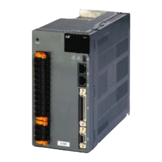
- Page 88 2. Product specification 2.2.2 Outline drawing L7SA001□ ~ L7SA004□ 2-Ø6 18.1 ★ Weight: 1.0[kg] L7SA008□ / L7SA010□ Ø6 127.7 2-Ø6 PE ( 17.2 *Weight: 1.5[kg] (including cooling pan) 2-48...
- Page 89 2. Product specification L7SA020□ / L7SA035□ 3-6Ø PE ( *Weight: 2.5[kg] (including cooling pan) L7SA050□ 130.4 4-Ø5.5 127.5 192.5 *Weight: 5.5[kg] (including cooling pan) 2-49...
- Page 90 2. Product specification L7SA075B 182.4 212.5 4-Ø6 122.8 *Weight: 9.7[kg] (including cooling pan) L7SA150B 4-Ø7 12.5 101.6 247.5 *Weight: 16.2[kg] (including cooling pan) 2-50...
- Page 91 2. Product specification L7SB010B Ø6 PE( ) 2-Ø6 *Weight: 1.5[kg] (including cooling pan) L7SB020B / L7SB035B 3-6Ø PE ( *Weight: 2.5[kg] (including cooling pan) 2-51...
- Page 92 2. Product specification L7SB050B 130.4 4-Ø5.5 127.5 192.5 *Weight: 5.5[kg] (including cooling pan) L7SA075B 182.4 4-Ø6 PE ( 130.5 177.5 *Weight: 9.7[kg] (including cooling pan) 2-52...
- Page 93 2. Product specification L7SB150B 4-Ø7 PE( ) 12.5 101.6 247.5 *Weight: 16.2[kg] (including cooling pan) 2-53...
-
Page 94: Options And Peripheral Devices
2. Product specification Options and Peripheral Devices ■ Option (Incremental encoder cable) Product Small capacity AMP Type INC encoder Classification For signal cable name Product Applicable All model of APM-SA/SB/SC/HB SERIES APCS- E name Motors (*Note 1) Motor Side Connector Dirve Side Connector Encoder Encoder... - Page 95 2. Product specification ■ Option [serial encoder cable] Classificatio Product Small capacity AMP Type serial encoder For signal cable (single turn) name Product Applicable All model of APM-SB/SC SERIES S-turn APCS- E name Motors (*Note 1) Motor Side Connector Dirve Side Connector L7 Biss Encoder Encoder...
- Page 96 2. Product specification ■ Option [serial encoder cable] Classificatio Product Small capacity Flat type motor serial encoder For signal cable(multi turn) name APCS- E ES1(Front Product Direction)/ Applicabl All model of APM-FAL/FBL/FCL SERIES M-turn e Motors name APCS- E ES1-R(Rear (*Note 1) Direction) Motor Side Connector...
- Page 97 2. Product specification ■ Option [serial encoder cable] Classific Product Medium-large capacity MS Type serial For signal encoder cable (multi turn) ation name Product Applicabl All models of APM-FE(P)/FF(P)/FG(P) name APCS- E e Motors SERIES M-turn (*Note 1) Motor Side Connector Dirve Side Connector Encoder Encoder...
- Page 98 2. Product specification ■ [200V] Option (Standard power cable) Product Classification Power Small capacity AMP Type power cable name Product Applicable All model of APM-SA/SB/SC/HB SERIES APCS- P name Motors (*Note 1) Motor Side Connector Dirve Side Connector Product name Pin No.
- Page 99 2. Product specification ■ [200V] Option (Standard power cable) Product Medium capacity MS Type power cable(for 130 Classification Power Flange) name Product Applicable All model of APM-FE/HE SERIES APCS- P name Motors (*Note 1) Motor Side Connector Dirve Side Connector Product name Pin No.
- Page 100 2. Product specification ■ [200V] Option (Standard power cable) Product Medium capacity MS Type power cable(180/ 220 Classification Power Flange) name FF30A, FF22D, FF35D, FF20G, FF30G,FF12M, Product Applicable FF20M, FF30M APCS- P name Motors (*Note 1) FG22D, FG35D, FG20G, FG12M, FG20M, FG30M Motor Side Connector Dirve Side Connector Product...
- Page 101 2. Product specification ■ [200V] Option (Standard power cable) Product Medium capacity MS Type power cable(180/ 220 Classification Power Flange) name Product Applicable FF50A, FF55D, FF44G, FF44M, FG55D, FG44G, APCS- P FG44M name Motors (*Note 1) Motor Side Connector Dirve Side Connector Name Phase Pin No.
- Page 102 2. Product specification ■ [200V] Option (Standard power cable) Product Medium capacity MS Type power cable(for 220 Classification Power Flange) name Product Applicable FG60M, FG75G APCS- P name Motors (*Note 1) Motor Side Connector Dirve Side Connector Name Phase Pin No. Specification LEAD WIRE...
- Page 103 2. Product specification ■ [200V] Option (Standard power cable) Classific Product Medium capacity MS Type power cable(for 220 Power Flange) ation name Product Applicabl name APCS- P FG150G e Motors (*Note 1) Motor Side Connector Dirve Side Connector Specifica Name Phase Pin No.
- Page 104 2. Product specification ■ [200V] Options spec. (small capacity L Series power cable) Product Classification Power Small capacity L Series power cable name Product Applicable APCS- P LS(Front Direction)/ All model of APM- FAL/ FBL/FCL Series name Motors APCS- P LS-R(Rear Direction) (*Note 1) Motor Side Connector...
- Page 105 2. Product specification ■ [400V] Option (Standard power cable) Product Medium capacity MS Type power cable(for 130 Classification Power Flange) name Product Applicable APCF- P All model of APM-FEP SERIES name Motors (*Note 1) Motor Side Connector Dirve Side Connector Product name Pin No.
- Page 106 2. Product specification ■ [400V] Option (Standard power cable) Product Medium capacity MS Type power cable(180/ 220 Classification Power Flange) name FFP30A, FFP22D, FFP35D, FFP20G, FFP30G, Product Applicable FFP12M, FFP20M, APCF- P FGP22D, FGP35D, FGP20G, FGP30G FGP12M, name Motors (*Note 1) FGP20M Motor Side Connector Dirve Side Connector...
- Page 107 2. Product specification ■ [400V] Option (Standard power cable) Product Medium capacity MS Type power cable(180/ 220 Classification Power Flange) name FFP50A, FFP55D, FFP75D, FFP44G, FFP60G, Product Applicable FFP30M, FFP44M, APCF- P FGP55D, FGP75D, FGP44G, FGP60G, FGP30M, name Motors (*Note 1) FGP44M Motor Side Connector Dirve Side Connector...
- Page 108 2. Product specification ■ [400V] Option (Standard power cable) Product Medium capacity MS Type power cable(for 220 Classification Power Flange) name Product Applicable FFP75G, FGP110D, FGP85G, FGP110G, APCF- P FGP150G, FGP60M name Motors (*Note 1) Motor Side Connector Dirve Side Connector Name Phase Pin No.
- Page 109 2. Product specification ■ [200V/ 400V] Option (Standard power cable) Product Medium capacity MS Type brake cable(for 220 Category Power Flange) Name Name Applicable All models of FGP Series(Common use of FG Series) APCS- P (Note 1) Motors Motor Side Connector Brake Power Connector Product name...
- Page 110 2. Product specification ■ Options spec. (cable) Classif Product Product Applicable Specification ication name drive name (Note 1) [Upper level controller] [Drive connector(CN1)] Pin no Pr oduct name 1. Drive connection (CN1) a. Socket spec.: SM-50J (SUNTONE) 10350-52A0-008(3M) b. Connector spec.: SM-50J(SUNTONE) 10150-3000VE(3M) c.
- Page 111 2. Product specification ■ Option spec. (connector) Classif Product Model name Applicable Specification ication name drive APC-VSCN1T CN1 T/B L7 SERIES APC-VPCN1T 1. APC-VSCN1T: CN1 T/B extended type of APD-VS a. APC-VPCN1T: CN1 T/B extended type of APD- b. Cable length can be changed c.
- Page 112 2. Product specification ■ [200V] Option spec (braking resistor) Clas Product Applicable sific Model name Specification Name drive ation APCS-140R50 L7SA001□ Resis Brake 50 [Ω] L7SA002□ resistor (140[W]) L7SA004□ APCS-300R30 L7SA008□ Resis Brake 30 [Ω] resistor L7SA010□ (300[W]) L7SA020□ APC-600R30 (2P) Resis Brake...
- Page 113 2. Product specification ■ [400V] Option spec (braking resistor) Clas Product Applicable sific Model name Specification Name drive ation APCS-300R82 Resis Brake 82 [Ω] L7SB010B resistor (300[W]) L7SB020B APC-600R140 (2P) Resis Brake 140 [Ω] resistor L7SB035B (600[W]) (2P) L7SB050B APC-600R875 (3P) Resis Brake...
- Page 114 2. Product specification 2-74...
-
Page 115: Installation
3. Installation Installation Servo Motor Caution If the encoder loses multi-turn data, there is a risk of equipment malfunction or accident, so be sure to operate after originating. When using an absolute value encoder, the multi-turn data of the encoder is lost in the following process. - Page 116 3. Installation Connect the U, V, and W terminals of the motor in the same way as the U, V, and W terminals of the drive. Ensure that the pins on the motor connector are securely attached. In order to protect against moisture or condensation in the motor, make sure that insulation resistor is 10 ㏁ ...
-
Page 117: Cable Installation
3. Installation 3.1.5 Cable Installation For vertical installations, make sure that no oil or water flows into the connecting parts. Do not apply pressure to or damage the cables. If the motor moves, be sure to use a movable cable and ensure that the cable does not swing. -
Page 118: Servo Drive
3. Installation Servo Drive 3.2.1 Operating Environment Environmental Item Remarks conditions Caution Ambient 0∼50[℃] Install a cooling fan on the control panel to maintain an temperature appropriate temperature. Caution Condensation or moisture may develop inside the drive during Ambient prolonged periods of inactivity and damage it. 90% RH or less humidity Remove all moisture before operating the drive after a... - Page 119 3. Installation 3.2.2 Installation in the Control panel The installation interval in the control panel is as shown in the figure below. In case of 1 unit installation 40mm or more 10mm 10mm or more or more 40mm or more...
- Page 120 3. Installation In case of installation of 2 or more units Install a cooling fan on the top of the servo drive to prevent the internal temperature of the control panel from exceeding the environmental conditions of the servo drive. Also, leave enough space while referring to the figure below to allow cooling by heat convection within the fan and control panel.
- Page 121 3. Installation 3.2.3 Power Supply Wiring Ensure that the input power voltage is within the acceptable range. Caution Over voltages can damage the drive. If commercial power is connected to U, V, W terminals of Drive, they may be damaged. Be sure to connect power to L1, L2, L3 terminals.
-
Page 122: Wiring Method
4. Wiring Method Wiring Method Internal block diagram L7 drive block diagram [L7SA001□ ~ L7SA004□] 4.1.1 Note1) If using a DC reactor, connect the PO and PI pins. Note2) If using an external regeneration resistor, remove the B and BI short-circuit pins and connect the B+ and B pins. Note3) Wire after checking the input power for each model. - Page 123 4. Wiring Method L7 drive block diagram [L7SA008□ ~ L7SA035□, 4.1.2 L7SB010B ~ L7SB035B] AC200~230V or AC380~480V Single phase power input AC200~230V or AC380~480V Note1) If using a DC reactor, connect the PO and PI pins. Note2) If using an external regeneration resistor, remove the B and BI short-circuit pins and connect the B+ and B pins.
- Page 124 4. Wiring Method 4.1.3 L7 drive block diagram [L7SA050□~L7SA075B, L7SB050B~L7SB075B] (Note2) External Regenerative (Note1) External regenerative resistor Resistance(separately Installed) (separately installed) (Note3) Diode IGBT Three-phase Power Input Regenerative Current Sensor Resistance AC200~230V AC200~230V or AC380~480V Thermister Chage Lamp T1 T2 Thermister Internal Regenerative...
- Page 125 4. Wiring Method 4.1.4 L7 drive block diagram [L7SA150B, L7SB150B] AC200~230V or AC380~480V Note1) If using a DC reactor, connect the PO and PI pins. Note2) The built-in regenerative resistor is not available in the L7SA150B model. It is basic to use an external regenerative resistor, and when installing, connect the external regenerative resistor to the B+ and B terminals.
-
Page 126: Power Supply Wiring
4. Wiring Method Power Supply Wiring L7 drive block diagram [L7SA001□ ~ L7SA035□, 4.2.1 L7SB010B~L7SB035B] AC 200~230[V] AC 380~480[V] Servo drive R S T (Note 1) Main DC reactor Main PO PI Motor (Note 5) Encoder Alarm+ +24V Alarm- (Note 2) External CN1(I/O) regenerative resistor... - Page 127 4. Wiring Method 4.2.2 L7 drive block diagram [L7SA050□~L7SA075B, L7SB050B~L7SB075B] AC 200~230[V] AC 380~480[V] Servo drive R S T (Note 1) Main Main reactor PO PI Motor (Note 3) Encoder Alarm+ +24V Alarm- (Note 2) External regenerative resistor Note1) It takes approximately one to two seconds until alarm signal is output after you turn on the main power. Accordingly, push and hold the main power ON switch for at least two seconds.
- Page 128 4. Wiring Method 4.2.3 L7 drive block diagram [L7SA150B, L7SB150B] AC 200~230[V] AC 380~480[V] Dervo drive R S T (Note 1) Main DC Reactor Main PO PI Motor (Note 3) Encoder Alarm+ +24V Alarm- (Note 2) External regenerative resistor Note1) It takes approximately one to two seconds until alarm signal is output after you turn on the main power. Accordingly, push and hold the main power ON switch for at least two seconds.
- Page 129 4. Wiring Method 4.2.4 Power circuit Electrical Components [200V Electronic component standard] L7SA001□ L7SA008□ L7SA020□ Name L7SA004□ L7SA050□ L7SA075B L7SA150B L7SA002□ L7SA010□ L7SA035□ 100A Frame 30A Frame 30A Frame 30A Frame 30A Frame 50A Frame 50A Frame 100A MCCB(NFB) (ABS103c/100 (ABE33b/5) (ABE33b/10) (ABE33b/15)
- Page 130 4. Wiring Method [400V Electrical Components standard] L7SB020B Name L7SB010B L7SB050B L7SB075B L7SB150B L7SB035B 30A Frame 30A Frame 30A Frame 30A Frame 50A Frame MCCB (NFB) (ABE33b/10) (ABE33b/20) (ABE33b/30) (ABE33b/30) (ABE53b/50) Noise Filter TB6-B010LBEI TB6-B020NBDC TB6-B030NBDC TB6-B040As TB6-B060LAs (10A) (20A) (30A) (40A) (60A)
- Page 131 4. Wiring Method (L7SA004□ or less) Wire strip (L7SA008□ ~ L7SA010□) Wire strip 4-17...
- Page 132 4. Wiring Method (L7SA020□ ~ L7SA035□) Wire strip For information on wiring to BLF 5.08 and BLZ 7.62HP Series connector, refer to the above procedures. Insert electric wire into insert hole with upper locking screw loosened, and use applicable flat head (-) driver for each model to fully tighten screw to 0.4-0.5 N·m.
- Page 133 4. Wiring Method (L7SA050□) NC : Internal regenerative resistance lead resistor terminal fixing bolt Terminal signal array Terminal screw: M4 Tightening torque: 1.20[N·m] Terminal screw: M4 Tightening torque: 1.20[N·m] Terminal screw: M4 Tightening torque: 1.20[N·m] Otherwise, insufficient torque of locking screw may cause vibration-induced disconnection, system malfunction and contact-induced fire accident.
- Page 134 4. Wiring Method (L7SA075B) NC : NC : Internal regenerative resistor lead terminal fixing bolt Terminal signal array Terminal screw: M5 Tightening torque: 2.70[N·m] Terminal screw: M5 Tightening torque:2.70[N·m] Terminal screw: M5 Tightening torque: 1.20[N·m] Otherwise, insufficient torque of locking screw may cause vibration-induced disconnection, system malfunction and contact-induced fire accident.
- Page 135 4. Wiring Method (L7SA150B) Terminal signal array Terminal screw: M6 Tightening torque: 4.70[N·m] Terminal screw: M4 Tightening torque: 1.20[N·m] Terminal screw: M5 Tightening torque: 2.70[N·m] Otherwise, insufficient torque of locking screw may cause vibration-induced disconnection, system malfunction and contact-induced fire accident. 4-21...
- Page 136 4. Wiring Method (L7SB010B) Wire Strip 7~10 [mm] Weidmueller's SD 0.6x3.5x100 M4: 1.2[N·m] (L7SB020B ~ L7SB035B) Strip 길이 7~10 [mm] Weidmueller's SD 0.6x3.5x100 M4 : 1.2 [N·m] 4-22...
- Page 137 4. Wiring Method For information on wiring to BLF 5.08 and BLZ 7.62HP Series connector, refer to the above procedures. Insert electric wire into insert hole with upper locking screw loosened, and use applicable flat head (-) driver for each model to fully tighten screw to 0.4-0.5 N·m. Otherwise, insufficient torque of locking screw may cause vibration-induced disconnection, system malfunction and contact-induced fire accident.
- Page 138 4. Wiring Method (L7SB050B) 400V AC380~480 NC : Internal regenerative resistor lead terminal fixing bolt Terminal signal array Terminal screw: M4 Tightening torque: 1.20[N·m] Terminal screw: M4 Tightening torque: 1.20[N·m] Terminal screw: M4 Tightening torque: 1.20[N·m] Otherwise, insufficient torque of locking screw may cause vibration-induced disconnection, system malfunction and contact-induced fire accident.
- Page 139 4. Wiring Method (L7SB075B) 400V AC380~480 NC: Internal regenerative resistor lead terminal fixing bolt Terminal signal array Terminal screw: M4 Tightening torque: 1.20[N·m] Terminal screw: M4 Tightening torque: 1.20[N·m] Terminal screw: M4 Tightening torque: 1.20[N·m] Otherwise, insufficient torque of locking screw may cause vibration-induced disconnection, system malfunction and contact-induced fire accident.
- Page 140 4. Wiring Method (L7SB150B) Terminal signal array Terminal screw: M5 Tightening torque: 2.70[N·m] Terminal screw: M4 Tightening torque: 1.20[N·m] Terminal screw: M5 Tightening torque: 2.70[N·m] Otherwise, insufficient torque of locking screw may cause vibration-induced disconnection, system malfunction and contact-induced fire accident. 4-26...
- Page 141 4. Wiring Method Connection Example with PLC device 4.3.1 LS ELECTRIC 1. XGF-PO1/2/3A (Open Collector) DC 24V I/O Power (Servo Drive) XGF-PO1/2/3A (Open Collector) +24V IN +24V GND24 +24V IN (DO1) PULCOM 49 ALARM+ 1.5K ALARM- P COM (DO3) ZSPD 1.5K...
- Page 142 4. Wiring Method 2. XGF-PD1/2/3A (Line Driver) DC 24V I/O Power (Servo Drive) XGF-PD1/2/3A (Line Driver) +24V IN +24V GND24 +24V IN 50 (DO1) ALARM+ Twisted Pair ALARM- (DO3) ZSPD (DO4) BRAKE (DO5) INPOS ALO0 Encoder Z Twisted phase output Pair ALO1 HOME +5V...
- Page 143 4. Wiring Method 3. XGF-PO1/2/3/4H (Open Collector) DC 24V I/O Power (Servo Drive) XGF-PO1/2/3/4H (Open Collector) +24V IN +24V GND24 +24V IN 50 (DO1) PULCOM 49 ALARM+ 1.5K P COM ALARM- P COM (DO3) ZSPD 1.5K (DO4) BRAKE ALO0 ALO1 Encoder Z Twisted ALO2...
- Page 144 4. Wiring Method 4. XGF-PD1/2/3/4H (Line Driver) DC 24V I/O Power (Servo Drive) XGF-PD1/2/3/4H (Line Driver) +24V IN +24V GND24 +24V IN 50 (DO1) P COM ALARM+ Twisted P COM ALARM- Pair (DO3) ZSPD (DO4) BRAKE ALO0 ALO1 Encoder Z Twisted ALO2 phase output...
- Page 145 4. Wiring Method 5. XBF-PD2A (Line Driver) DC 24V I/O Power (Servo Drive) XBF-PD02A (Line Driver) +24V IN +24V GND24 +24V IN 50 주1) (DO1) P COM ALARM+ Twisted P COM ALARM- Pair (DO3) ZSPD (DO4) BRAKE ALO0 ALO1 Encoder Z Twisted ALO2 phase output...
- Page 146 4. Wiring Method 6. XBM-DN**S (Open Collector) DC 24V I/O Power (Servo Drive) XBM-DN**S (Open Collector) +24V IN +24V GND24 +24V IN 50 주1) (DO1) PULCOM 49 ALARM+ 1.5K ALARM- +24V DC24 (DO3) ZSPD Pulse 1.5K (DO4) BRAKE Output Common ALO0 Direction ALO1...
- Page 147 4. Wiring Method 7. XBC/XEC-DNxxH (Open Collector) DC 24V (Servo Drive) XBC/XEC-DNxxH I/O Power (Open Collector) +24V IN +24V GND24 +24V IN 50 (DO1) PULCOM 49 ALARM+ 1.5K ALARM- +24V (DO3) ZSPD Pulse 1.5K %QX0.0.0 (DO4) BRAKE Output Common ALO0 Direction %QX0.0.2 ALO1...
-
Page 148: Timing Diagram
4. Wiring Method Timing diagram 4.4.1 Timing diagram when power is turned on In the L7 Series, power is supplied to the control circuit when single-phase power is connected to C1 and C2 terminals, and power is supplied to the main circuit when 3-phase power is connected to L1, L2, and L3. - Page 149 4. Wiring Method 4.4.2 Timing chart when an alarm occurs When an alarm occurs in the servo drive, PWM is blocked and the motor stops. Caution Remove the cause of the alarm and reset the alarm after turning off the servo motor drive command (servo ON) signal.
-
Page 150: Control Signal Wiring
4. Wiring Method Control signal wiring 4.5.1 Contact input signal Caution 2. There are A contact and B contact depending on the characteristics of each signal, and it can be set by [P2-08] and [P2-09]. 3. Each contact can be forcibly turned ON/OFF by [Cn-07]. When the power is turned off, each contact is automatically turned off, so special attention is required when using it. -
Page 151: Contact Output Signal
4. Wiring Method 4.5.2 Contact output signal Caution 1. There are A contact and B contact for the output contact according to the characteristics of each signal, and it can be set by [P2-10]. 2. Each contact can be forcibly turned ON/OFF by [Cn-08]. When the power is turned off, each contact is automatically turned off, and so special attention is required when using it. - Page 152 4. Wiring Method 4.5.3 Analog input and output signal 1. Set GND to 0[V] of the control power supply. 2. Use the input signal command voltage within ±10[V] and the input impedance is 22[㏀]. 3. Monitor 1 (No. 28), Monitor 2 (No. 29) output signal voltage is ±10 [V]. Also, refer to the figure below when adjusting the analog input with a variable resistor using the drive-supplied power supply.
- Page 153 4. Wiring Method 4.5.4 Pulse string input signal (1) Line drive(5[V]) Pulse input Twisted Pair Shield Wire Host controller Servo drive Line receiver Line drive (2) Open collector (24[V]) Pulse input Host controller <Servo drive> GND24 +24[V] Pulse COM Shield Wire GND24 (3) 12[V] or 5[V] NPN open collector pulse command Host controller...
-
Page 154: Host Controller
4. Wiring Method (4) PNP open collector type pulse command Host controller <Servo drive> Power Note1) Note1) When using 5[V] power: R= 100~150[Ω], 1/2[W] When using 12[V] power: R= 560~680[Ω], 1/2[W] When using 24[V] power: 저항 R= 1.5[kΩ], 1/2[W]. 4.5.5 Encoder output signal Since the encoder signal is output based on GND of the control power supply, connect the GND terminal of the host control device and the GND terminal of CN1. - Page 155 4. Wiring Method Quadrature Encoder Signaling unit (CN2) wiring 4.6.1 APCS-E AS cable AWG24 7Pair Twisted Shield Wire Servo Motor Servo Drive Encoder Cable Connector(CN2) Cable Maker – 3M Connector 10314-52A0-008 Maker - AMP 10114-3000VE 172163-1 Frame 170361-1 4.6.2 APCS-E BS cable AWG24 7Pair Twisted Servo Motor...
- Page 156 4. Wiring Method Serial Encoder Signaling unit (CN2) wiring 4.7.1 APCS-E CS cable AWG24 4Pair Twisted Shield Wire Servo Motor Servo Drive Encoder Cable Connector(CN2) Cable Maker – 3M Connector 10314-52A0-008 Maker - AMP 10114-3000VE 172161-1 Frame 170361-1 4.7.2 APCS-E DS cable AWG24 4Pairs Twisted Servo motor...
- Page 157 4. Wiring Method 4.7.3 APCS-E ES cable Servo AWG24 4Pairs Twisted Servo drive motor Shield Wire Encoder Cable Connector(CN2) Maker – 3M 10314-52A0-008 10114-3000VE Connector Tyco Connector Frame (7Ciruits) 4-43...
- Page 158 4. Wiring Method Multi Encoder Signaling unit (CN2) wiring 4.8.1 APCS-E CS1 cable AWG24 4Pairs Twisted Servo motor Servo drive Shield Wire Encoder BAT+ BAT- Cable Connector(CN2) Maker – 3M 10314-52A0-008 Cable 10114-3000VE Connector MS3108B20-29S Frame 4.8.2 APCS-E DS1 cable AWG24 4Pairs Twisted Servo motor Servo drive...
- Page 159 4. Wiring Method 4.8.3 APCS-E ES1 cable AWG24 4Pairs Twisted Servo motor Servo drive Shield Wire Encoder BAT+ BAT- Cable Connector(CN2) Maker – 3M 10314-52A0-008 Connector 10114-3000VE Tyco Connector Frame (7Ciruits) 4-45...
-
Page 160: Absolute Encoder Data Transmission
4. Wiring Method Absolute encoder data transmission 4.9.1 Absolute encoder data transmission When absolute value data is requested from the absolute encoder, the absolute encoder data is transmitted to the host controller in the form of quadrature pulses through the output of AO and BO, which are encoder output signals. -
Page 161: Parameter Description
5. Parameter Description Parameter Description How to operate the loader 5.1.1 Name of each parts and function Displays 5-digit FND data. DIGIT5 DIGIT4 DIGIT3 DIGIT2 DIGIT1 Indicates whether or not there is a decimal point. ex) 123.4 [MODE]: Change display mode [/LEFT]: Data digit shift In case of 16Bit, “-”... - Page 162 5. Parameter Description 5.1.2 Status summary diaplay (1) Status summary display in speed mode. ① Servo OFF status example in speed control mode DIGIT3~1: Display current servo status bb - servo OFF status run - servo ON status ...
- Page 163 5. Parameter Description (2) Summary display list of servo operation status The operation status summary display contents for each servo mode are listed as follows. Operation status Function Reference screen Servo OFF status display in position mode Servo ON status display in position mode CCW status display in position mode CW status display in position mode Servo OFF status display in speed mode...
-
Page 164: Parameter Operation
5. Parameter Description 5.1.3 Parameter operation (1) Parameter move Example of changing speed control mode to position control mode ([P0-03]: 00001 -> 00002) St-26 P0-27 P4-13 Cn-15 P1-25 P2-22 P3-20 St-25 P0-26 P4-12 Cn-14 St-24 P0-25 P4-11 Cn-13 DOWN St-02 P0-02 P4-02 Cn-02... - Page 165 5. Parameter Description (2) Example of changing speed control mode to position control mode ([P0-03]: 00001 -> 00002) Loader display after key to use Operation explanation operation Displays speed control mode with main power and control power applied Press the [MODE] key to move to [P0- 00].
- Page 166 5. Parameter Description (3) Example of changing speed proportional gain 2 ([P1-07]: 200 [rad/s] -> 500 [rad/s]) Loader display after key to use Operation explanation operation Displays speed control mode with main power and control power applied Press the [MODE] key to move to [P1- 00].
- Page 167 5. Parameter Description (4) Example of changing DAC output offset 1 ([P0-19]: 0[Unit/V] -> -500[Unit/V]) Loader display after key to use Operation explanation operation Displays speed control mode with main power and control power applied Press the [MODE] key to move to [P0- 00].
-
Page 168: Data Display
5. Parameter Description 5.1.4 Data display (1) Binary ① Minimum(0b00000) ② Maximum(0b11111) (2) Hex ① Minimum(0x0000) ② Maximum(0xFFFF) (3) 16Bit Unsigned Integer ① ex) 0 ② ex) +1234 (4) 16Bit Signed Integer ① ex) -1234 ② ex) +5678 ① ex) -1234 ②... - Page 169 5. Parameter Description (6) 32Bit Signed Integer data display ① Minimum(-2147483648) <Show upper 2 digits> <Show middle 4 digits> <Show lower 4 digits> ② Maximum(2147483647) <Show upper 2 digits> <Show middle 4 digits> <Show lower 4 digits> Operation Example) [St-16]: upper=0, middle=0012, lower=2071 are displayed.
- Page 170 5. Parameter Description 5.1.5 External input signal display [St-14] Check the ON/OFF status of digital input/output signals connected to the servo drive. (1) External input signal display Positioning of the 7-segment LED. The CN1 connector pins correspond as follows. When the LED at the location corresponding to the pin is turned on, it indicates ON, and when it is turned off, it indicates OFF.
- Page 171 5. Parameter Description 5.1.6 External input signal and logic definition The allocation of input signals and how to check the allocation status are shown below. (1) Assignment of input signal In the L7 drive, a total of 19 input contact points can be assigned to 10 hardware points. [P2-00], [P2-01], [P2-02], [P2-03], [P2-04] parameters of each input contact function are arranged in the designated DIGIT, and the value of the corresponding DIGIT is changed.
- Page 172 5. Parameter Description Signal name Alwa CN1 pin default assignment number Input Defaul Input allo Signal Parameter sign assi cate Definitio setting assignment gned value Servo On[P2-00] DIGIT1 setting Multi-speed1 [P2-00]. DIGIT2 setting [P2-00] 0x4321 Multi-speed2 [P2-00]. DIGIT3 setting Multi-speed3 [P2-00].
- Page 173 5. Parameter Description (2) Example of changing input signal allocation Input signal definition can be changed in [P2-00], [P2-01], [P2-02], [P2-03], [P2-04]. Input signal logic definition can be changed in [P2-08], [P2-09] When assigning input signals as follows, set them as shown in the table below. Input signal Input allocation No.
- Page 174 5. Parameter Description Signal name Alwa CN1 pin default assignment number Input Set value Input Signal Parameter alloc after Signal assi Definitio ated change assignment gned Servo On [P2-00]. DIGIT1 SVON setting multi-speed 1 SPD1 [P2-00]. DIGIT2 setting [P2-00] 0x0321 multi-speed 2 SPD2 [P2-00].
- Page 175 5. Parameter Description Handling example of changing input signal allocation An example of changing the assignment of input signals is shown below. The sequence of swapping SVON (CN1-47) and STOP (CN1-48) allocation signals is as follows. Before change After change [P2-00] : [P2-02] : Sequence...
- Page 176 5. Parameter Description (3) Input signal logic definition In the L7 drive, the logic of the input signal can be defined through [P2-08] and [P2-09] parameters for 10 hardware contacts from DI1 to DIA. The logic status of input signals at the time of shipment is shown in the figure below. Input signal Input signal logic definition DI1(A contact/...
- Page 177 5. Parameter Description Signal name Input CN1 pin default assignment number Input Default signal Conta signal Parameter setting (initial ct B logic assignment value name) definition Servo On [P2-08]. DIGIT1 SVON setting multi-speed 1 [P2-08]. DIGIT2 SPD1 setting multi-speed 2 [P2-08].
-
Page 178: Input Signal
5. Parameter Description (4) Example of changing input signal logic definition Input signal logic definition can be changed in [P2-08], [P2-09] When assigning input signals as follows, set them as shown in the table below. Input signal Input signal logic definition SVON DI1(A contact/B contact) SPD1... - Page 179 5. Parameter Description Signal name CN1 pin default assignment number Input Default Input Conta signal Parameter setting Signal ct B: logic assignment value definition Servo On [P2-08]. DIGIT 1 SVON setting multi-speed 1 [P2-08]. DIGIT 2 SPD1 setting multi-speed 2 [P2-08].
- Page 180 5. Parameter Description Handling example of changing input signal logic definition An example of changing the logic of input signals is shown below. The order of changing logic signal contact A of SVON (CN1-47) to contact B and the order of changing logic signal contact B of CCWLIM (CN1-20) to contact A are as follows.
- Page 181 5. Parameter Description 5.1.7 External output signal display [St-15] You can check the ON/OFF status of digital input/output signals connected to the servo drive. (1) External output signal display Positioning of the 7-segment LED. The CN1 connector pins correspond as follows. When the LED at the location corresponding to the pin is turned on, it indicates ON, and when it is turned off, it indicates OFF.
-
Page 182: Assignment Of Output Signal
5. Parameter Description 5.1.8 External output signal and logic definition The allocation of output signals and how to check the allocation status are shown below. (1) Assignment of output signal Output signal definition: [P2-05], [P2-06], [P2-07] Output signal logic definition: [P2-10] ... - Page 183 5. Parameter Description (2) Example of changing output signal allocation Output signal definition can be changed in [P2-05], [P2-06], [P2-07]. Output signal logic definition can be changed in [P2-10] When assigning output signals as follows, set them as shown in the table below. Output signal ALARM Output allocation No.
- Page 184 5. Parameter Description Handling example of changing output signal allocation An example of changing the assignment of output signals is shown below. The sequence of swapping ALARM (CN1-38/39) and ZSPD (CN1-43) allocation signals is as follows. Before change After change [P2-05]: Sequence Loader window...
- Page 185 5. Parameter Description (3) Output signal logic definition Output signal logic definition: [P2-10] The logic status of output signals at the time of shipment is shown in the figure below. Output signal ALARM Output signal logic READY definition ZSPD DO1(A contact/B contact) BRAKE...
- Page 186 5. Parameter Description (4) Example of changing output signal logic definition Output signal logic definition can be changed in [P2-10] When assigning output signals as follows, set them as shown in the table below. Output signal ALARM Output signal logic definition READY ZSPD DO1(A contact/B contact)
- Page 187 5. Parameter Description Handling example of changing output signal logic definition An example of changing the assignment of output signals is shown below. The sequence of swapping ALARM (CN1-38/39) and ZSPD (CN1-43) allocation signals is as follows. Before change After change [P2-05]: Sequence...
- Page 188 5. Parameter Description Parameter Description 5.2.1 Parameter description Parameter configuration consists of a total of 8 groups, and the description of each configuration is shown in the table below. Paramete Paramete Parameter Initial screen r group Description r move number name ex) Speed mode Status...
- Page 189 5. Parameter Description 5.2.2 Operation status display parameter For detailed explanation, refer to “5.3 Operation Status Display”. “**”Parameters that cannot be modified and power reset when servo is ON, parameters that cannot be modified when “*” servo is ON Parameter Unit Initial Applica...
- Page 190 5. Parameter Description Parameter Unit Initial Applica Description Minim Maxim Code Name mode Accumulated Displays the current cumulative load factor as a overload percentage percentage of the maximum cumulative load factor. St-09 Accumulated (Details: Refer to “5.3.4 Display related to torque and -300.0 300.0 load)
- Page 191 5. Parameter Description PARAMETER Unit Initial Applica Description Minim Maxim Code Name mode Internal temperature [℃] St-19 Displays the internal temperature sensor value. Room Temperature Motor rated speed [RPM] St-20 Displays the rated speed of the currently installed motor. Rated RPM 10000 Motor maximum [RPM]...
- Page 192 5. Parameter Description 5.2.3 System setting parameter For details, refer to “5.4.1 System Parameter Setting”. “**” Parameters that cannot be modified and power reset when servo is ON, parameters that cannot be modified when servo is ON Parameter Unit Initial Applic Description able...
- Page 193 5. Parameter Description Parameter Unit Initial Applic Description able Minim Maxim Code Name mode RST check hour [ms] This specifies the checking interval for main power P0-07 RST Check Time 5000 phase loss. At start Display Set the number of operation status parameters to be parameter P0-08 displayed at startup.
- Page 194 5. Parameter Description Parameter Unit Initial Applic Description able Minim Maxim Name Code mode Set the function of the drive by DIGIT DIGIT 1 -> Sets the driving direction of the servo. Function setting 0: Forward(CCW), Reverse(CW) 0b00000 1: Forward(CW), Reverse(CCW) DIGIT 2 ->...
- Page 195 5. Parameter Description Parameter Unit Initial Applica Description Minimu Maxim Code Name mode DAC output scale1 [Unit/V] (MONIT1) Set the magnification of analog output channels 1~2. P0-23 DAC Scale1(F) Magnification setting with setting Unit/V 10000 (MONIT1) ex) Channel 1 scale 100[RPM]: Outputs 100[RPM] as DAC output scale 2 [Unit/V] 1[V].
- Page 196 5. Parameter Description 5.2.4 Control parameter setting “**” Parameters that cannot be modified and power reset when servo is ON, parameters that cannot be modified when servo is ON Parameter Unit Initial Applic Description able Minim Maxim Code Name mode Set the inertia ratio of the load.
- Page 197 5. Parameter Description Parameter Unit Initial Applic Description able Minim Maxim Code Name mode Torque command filter [ms] Set the time constant of the filter for the torque time constant P1-12 Trq. Command Filter command value. 1000 Time Constant Forward rotation torque limit P1-13 Set the torque limit value for forward rotation.
- Page 198 5. Parameter Description Parameter Unit Initial Applica Description Minim Maxim Code Name mode Automatic gain tuning Set the round-trip operation distance during distance P1-21 Auto Gain Tuning automatic gain tuning operation. Distance Set the speed limit mode for torque control. ...
- Page 199 5. Parameter Description 5.2.5 Input/Output parameters setting For details, refer to “5.4.3 Analog I/O Parameter Setting” and “5.4.4 I/O Parameter Setting”. “**” Parameters that cannot be modified and power reset when servo is ON, parameters that cannot be modified when servo is ON. Parameter Unit Initial...
- Page 200 5. Parameter Description Parameter Unit Initial Applic Description able Minim Maxim Code Name mode Defines logic of CN1 connector for digital input signals. (0: B contact, 1: A contact) Input signal logic 0b11111 Initial input logic definition definition 1 ...
- Page 201 5. Parameter Description Parameter Unit Initial Applic Description able Minim Maxim Code Name mode Analog Velocity Set the speed command scale when the analog [RPM] 2000 Command Scale speed command is 10[V]. *P2-17 (Details: Refer to “5.4.3 Analog Inout/Output Parameter Analog Speed 15000 Command Scale...
- Page 202 5. Parameter Description 5.2.6 Speed operation setting parameters “**” Parameters that cannot be modified and power reset when servo is ON, parameters that cannot be modified when servo is ON Parameter Unit Initial Description Minimu Maxim Code Name Set speed command 1~6 according to speed Speed command 1 [RPM] command input contact.
- Page 203 5. Parameter Description Parameter Unit Initial Description Minimu Maxim Code Name Program JOG operation [RPM] speed 1 P3-13 Program Jog Speed1 -6000 6000 During program JOG operation, sets the operation Program JOG operation [RPM] 3000 speed/operation time for [Cn-01] programs 1 to 4 speed 2 P3-14 Test operation is repeated from Step 1 to Step 4...
- Page 204 5. Parameter Description 5.2.7 Position operation setting parameters “**” Parameters that cannot be modified and power reset when servo is ON, parameters that cannot be modified when servo is ON Parameter Unit Initial Description Minimu Maxim Name Code Set the logic of position operation input pulse. - Position command input pulse type and the rotation direction for each logic are as follows: PF+PR...
- Page 205 5. Parameter Description Parameter Unit Initial Description Minimu Maxim Name Code Electronic gear ratio Set the electronic gear ratio numerator/denominator 1, 2, 1000 numerator 1 3, 4. *P4-01 Electronic gear ratio Electric Gear Num.1 2^21 EGEAR EGEAR Electronic Numerator/denomin Electronic gear ratio gear ratio 1000 ator...
-
Page 206: Operation Parameters
5. Parameter Description 5.2.8 Operation parameters “**” Parameters that cannot be modified and power reset when servo is ON, parameters that cannot be modified when servo is ON Parameter Unit Initial Description Minimu Maxim Name Code Manual JOG operation Manual JOG operation is performed by the drive alone. (Refer to Chapter 5 Operation and Operation”) ... - Page 207 5. Parameter Description Parameter Unit Initial Description Minimu Maxim Name Code Automatic gain tuning operation is performed Automatic gain tuning Related parameters as shown below. Cn-05 [P1-22]: Automatic gain tuning speed [P1-23]: Automatic gain tuning distance Auto Gain Tuning (Details: Refer to “6.2 Handling and Operating”) Operates Phase Z detection operation.
- Page 208 5. Parameter Description Parameter Unit Initial Description Minimu Maxim Code Name Manual speed Offset of analog speed command is manually corrected. command offset The voltage range that can be set is -1V to 1V. correction Offset voltages greater than this range are displayed as [oVrnG] and are not compensated for.
-
Page 209: Operation Status Display
5. Parameter Description Operation status display 5.3.1 Status display 1. Current operating status [St-00] display current operating status (Refer to “5.1.2 Status summary display”) 5.3.2 Speed display 1. Current operation speed [St-01] Display current operation speed in [RPM] unit. 2. Current command speed [St-02] Display current command speed in [RPM] unit 5.3.3 Position display... -
Page 210: I/O Status Display
5. Parameter Description 5.3.5 I/O status display 1. CN1 I/O input status[St-14] Refer to “5.1.5 External Input Signal Display [St-14]” 2. CN1 I/O Output contacts status[St-15] Refer to “5.1.7 External Output Signal Display [St-15]” 5.3.6 Other status and data display 1. -
Page 211: System Parameter Setting
5. Parameter Description Parameter setting 5.4.1 System parameter setting 1. Motor ID setting [P0-00] Please refer to ID: xxx of INPUT on the label attached to the motor. 2. Encoder setting Encoder type [P0-01] Please refer to the Encoder information on the label attached to the motor and the table below. ... - Page 212 5. Parameter Description The setting value is divided into 0 to 25 from [St-00] to [St-25] and sets the number of the corresponding parameter. 8. Regenerative overload derating factor setting [P0-09] This specifies the derating factor which checks for regenerative resistor overloads. If the derating value is set below 100%, an overload alarm occurs at a time proportional to the set value.
- Page 213 5. Parameter Description Alarm Code Group Alarm Code Name AL-10 IPM Fault AL-11 IPM Temperature Current AL-14 Over Current AL-15 Current Offset AL-16 Over Current AL-21 Continuous Overload Load AL-22 Room Temperature AL-23 Regen Overload AL-24 Motor Cable Open AL-30 Encoder Comm AL-31 Encoder Cable Open...
- Page 214 5. Parameter Description 5.4.2 Control parameter setting The setting sequence of control parameters is as follows. Load inertia ratio [P1-00] setting: Refer to “6.2.6 Automatic Gain Tuning [Cn-05]” Position proportional gain [P1-01], [P1-02] adjustment Increase within the range where the servo motor does not overshoot or oscillate. (Do not use during speed operation or torque operation.) ...
-
Page 215: Speed Control Gain
5. Parameter Description Position proportional gain [P1-01], [P1-02]: The difference between the position command and the current position is converted into a speed command by multiplying the position proportional gain. * Recommended setting = speed proportional gain [P1-06] / 10 ... - Page 216 5. Parameter Description Speed proportional gain [P1-06]: The speed error is multiplied by the proportional gain and converted into a torque command. If this value is large, the speed response becomes faster and the speed followability increases, but if it is too large, vibration occurs. Also, if this value is small, the speed response becomes slow, and the speed follow-up becomes poor, and the servo loses power.
- Page 217 5. Parameter Description (8) P / PI switching mode setting [P1-15 DIGIT2] Set the P, PI control switching mode. [0xF0 (DIGIT 2)] 0: only PI control 1: P control when the command torque is higher than the set torque [P1-24] ...
- Page 218 5. Parameter Description 5.4.3 Analog input/output parameter setting (1) Analog speed scale setting Analog speed command scale [P2-17]: Set the analog speed command value at 10 [V] in [RPM] unit. At this time, the maximum setting value is the maximum motor speed. ...
- Page 219 5. Parameter Description 5.4.4 I/O parameter setting (1) Position operation parameter setting Position reach output range [P2-11]: When the error pulse value, which is the difference between the command position pulse and the tracking position pulse, is within the setting range, the positioning completion signal is output.
- Page 220 5. Parameter Description (2) Speed control parameter setting Speed Command speed Speed reached output range [P2-13] Zero speed output range[P2-12] Time Zero speed(ZSPD) Speed reached(INSPD) Zero speed output range [P2-12]: When the current speed is below the set speed, the zero speed signal is output.
- Page 221 5. Parameter Description (4) Position pulse clear mode [P2-16] Set the operation method of position pulse clear mode in position operation mode Setting Operation method Operates only at the edge that converts contact OFF -> ON Does not operate in OFF or ON state Operates immediately when the contact is on_Level and maintains torque when high is input.
- Page 222 5. Parameter Description 5.4.5 Speed operation parameter setting (1) Speed command [P3-00]~[P3-06] You can operate by setting the operation speed in [RPM] units. The operation speed is selected according to the speed command input contact point. SPD1 SPD2 SPD3 Speed control Analog speed command Digital speed command 1 Digital speed command 2...
- Page 223 5. Parameter Description 5.4.6 Position operation parameter setting (1) Input pulse logic [P4-00] Set the type of position command input pulse and the rotation method for each logic. 0: A+B 1: CW+CCW, positive logic 2: Pulse+sign, positive logic ...
- Page 224 5. Parameter Description (2) Electrical gearing [P4-01]~ [P4-08] The electronic gear ratio sets the relationship between the position command input pulse and the motor encoder pulse as a numerator/denominator, and is set so that no error occurs during position operation. The setting method is as follows. Electrical gear ratio = feed per input pulse ×...
- Page 225 5. Parameter Description List of alarms and warnings 5.5.1 Summary display list of servo alarm status When an alarm occurs, the fault signal output contact point (ALARM) is turned off, and the motor is stopped by Dynamic Brake. Alarm Name Content Check Items Code...
- Page 226 5. Parameter Description Alarm Name Content Check Items Code ※After replacing the battery, power is re- applied and origin operation is required. (Applies from S/W Ver 1.28) Back-up battery replacement when using absolute encoder. Lack of voltage and first coupling of encoder.
- Page 227 5. Parameter Description 5.5.2 Summary display list of servo warning status If a warning code is displayed in the current operation status [St-00], the servo drive is operating in an abnormal state, so check the parts corresponding to the inspection items. Warning status Name...
-
Page 228: Check Wiring
6. Handling and Operating Handling and Operating Checklist before driving In order to prevent safety accidents and product damage caused by servo motor operation during trial operation, check the following and take measures to ensure that there are no problems. 6.1.1 Check wiring 1. - Page 229 6. Handling and Operating 6.1.3 Check operating atmosphere Check that there is no metallic powder or moisture in the wiring area. 6.1.4 Machine status check 1. Are there any abnormalities in the servo motor coupling? 2. Is there any loosening or breakaway of fastening bolts? 3.
- Page 230 6. Handling and Operating Handling and Operating 6.2.1 Manual JOG operation [Cn-00] Manual JOG operation is performed by the drive alone. 1. [Jog] is displayed when [SET] key is pressed in [Cn-00] (However, when EMG, CW/CCW contact is ON in external I/O) 2.
- Page 231 6. Handling and Operating 6.2.2 Programs JOG operation [Cn-01] It operates continuously according to a pre-determined program. 1. [P-Jog] is displayed when [SET] key is pressed in [Cn-01] parameter. 2. When [SET] key is pressed, [run] is displayed and after servo ON, program JOG operation is performed.
- Page 232 6. Handling and Operating 6.2.3 Alarm reset [Cn-02] Reset the generated alarm. 1. Contact alarm reset: If ALMRST is turned ON during the input contact point, the alarm status is reset and becomes normal. 2. Operation alarm reset: If you press the [SET] key in the alarm reset [Cn-02] parameter among operation parameters, [ALrst] is displayed, and if you press the [SET] key again, the alarm is reset and returns to the normal status.
- Page 233 6. Handling and Operating 6.2.4 Alarm history read [Cn-03] Check the saved alarm code history. [Example of alarm history read operation method] Loader display after Sequence key to use Operation explanation operation Displays speed control mode with main power and control power applied.
- Page 234 6. Handling and Operating 6.2.5 Alarm history reset [Cn-04] Delete all the saved alarm code. [Example of alarm history reset operation method] Loader display after Sequence key to use Operation explanation operation Displays speed control mode with main power and control power applied.
- Page 235 6. Handling and Operating 6.2.6 Automatic gain tuning [Cn-05] Automatic tuning operation is performed. 1. [Auto] is displayed when [SET] key is pressed in [Cn-05] parameter. 2. When [SET] key is pressed, [run] is displayed and automatic gain tuning starts. If an alarm occurs at this time, check the wiring of the servo or other sources of alarm, take action, and then try again.
- Page 236 6. Handling and Operating 6.2.7 Phase Z search operation [Cn-06] Operates Phase Z search operation. 1. [Z-rtn] is displayed when [SET] key is pressed in [Cn-06]. 2. When [SET] key is pressed, [run] is displayed and the servo is in ON status. 3.
- Page 237 6. Handling and Operating 6.2.8 Force input contact ON/OFF [Cn-07] Forcibly ON/OFF the input contact by the drive alone without the upper controller and I/O jig. (1) Forced input ON/OFF Setting Positioning of the 7-segment LED and CN1 contact correspond as follows. When the LED at the location corresponding each contact is turned on, it indicates ON, and when it is turned off, it indicates OFF.
- Page 238 6. Handling and Operating (2) Example of Forced input contact ON/OFF (SVON ON → EMG ON → EMG OFF → SVON OFF) [Example of Forced input contact ON/OFF] Loader display after Sequence key to use Operation explanation operation Press the [MODE] key to move to [Cn-00].
- Page 239 6. Handling and Operating 6.2.9 Force input contact ON/OFF [Cn-08] Forcibly ON/OFF the output by the drive alone without the upper controller and I/O jig. (1) Forced output ON/OFF setting Positioning of the 7-segment LED and CN1 contact correspond as follows. When the LED at the location corresponding each contact is turned on, it indicates ON, and when it is turned off, it indicates OFF.
- Page 240 6. Handling and Operating 6.2.10 Parameter default [Cn-09] Initialize parameter data. [Example of how to operate the parameter default] Loader display after Sequence key to use Operation explanation operation Displays speed control mode with main power and control power applied. Press the [MODE] key to move to [Cn-00].
- Page 241 6. Handling and Operating 6.2.11 Automatic speed command offset compensation [Cn-10] Offset of analog speed command is automatically corrected. The adjustable speed command analog voltage range is +1V to -1V. Offset voltages greater than this range are displayed as [oVrnG] over range and are not compensated for. The corrected offset can be checked in [P2-18] analog speed offset.
- Page 242 6. Handling and Operating 6.2.12 Automatic torque command offset compensation [Cn-11] Offset of analog torque command is automatically corrected. The adjustable torque command analog voltage range is +1V to -1V. Offset voltages greater than this range are displayed as over range [oVrnG] and are not compensated. The corrected offset can be checked in [P2-21] analog torque offset.
- Page 243 6. Handling and Operating 6.2.13 Manual speed command offset compensation [Cn- Offset of analog speed command is manually corrected. The adjustable speed command analog voltage range is +1V to -1V. Offset voltages greater than this range are displayed as [oVrnG] over range is called are not compensated. The corrected offset can be checked in [P2-18] analog speed offset.
- Page 244 6. Handling and Operating 6.2.14 How to operate Manual speed command offset compensation [Cn-13] Offset of analog torque command is manually corrected. The adjustable torque command analog voltage range is +1V to -1V. Offset voltages greater than this range are displayed as [oVrnG] over range and are not compensated. The corrected offset can be checked in [P2-21] analog torque command offset.
- Page 245 6. Handling and Operating 6.2.15 Absolute encoder reset [Cn-14] Initialize encoder multi-turn data to 0. [Example of how to reset the absolute value encoder] Loader display Sequence key to use Operation explanation after operation Press the [MODE] key to display [Cn-00].
- Page 246 6. Handling and Operating 6.2.16 Instantaneous maximum load rate initialization [Cn- This function initializes the instantaneous maximum load rate to 0. [Example of how to initialize the instantaneous maximum load ratio] Loader display after Sequence key to use Operation explanation operation Press the [MODE] key to move to [Cn-00].
- Page 247 6. Handling and Operating 6.2.17 Parameter locking [Cn-16] Set parameter lock. [Example of how to operate the parameter lock setting] Loader display after Sequence key to use Operation explanation operation Press the [MODE] key to display [Cn-00]. Press the [Up] or [DOWN] key to move to [Cn-16].
-
Page 249: Communication Protocol
7. Communication protocol Communication protocol Overview and Communication spec. 7.1.1 Overview The L7 servo drive can use functions such as trial run, gain tuning, parameter change, and indexer operation of the drive by connecting it to a host controller such as a handy loader, HMI, PC, or PC through RS-422 serial communication. -
Page 250: Communication Spec
7. Communication protocol 7.1.2 Communication specification and cable connection diagram (1) Communication spec. Item Specification Communication standard ANSI/TIA/EIA-422 standard Communication protocol MODBUS-RTU Data bit 8bit Data Type Stop bit 1bit Parity None Synchronization type Asynchronous type 9600 /19200/38400/57600 [bps] Transmission speed [P0-04] selectable Transmission distance Up to 200[m]... - Page 251 7. Communication protocol Communication protocol basic structure In principle, communication of L7 servo drive complies with MODBUS-RTU protocol. For matters not mentioned in this manual, refer to the relevant standards below. (Relevant standards: Modbus Application Protocol Specification 1.1b, 2006.12.28) In addition the concepts of sending/ receiving in this manual are defined based on the host. 7.2.1 Sending and receiving packet structure The maximum transmit/receive packet length of MODBUS-RTU protocol is 256 bytes.
-
Page 252: Protocol Packet Code Description
7. Communication protocol (3) Protocol Packet Code Description Node ID Indicates the station number of the servo drive to be transmitted. Station number of servo drive is set in [P0-05]. Function Code The function codes of the Modbus-RTU standard supported by the L7 servo drive are as follows. Command Usage Category... - Page 253 7. Communication protocol 7.2.2 Protocol Command Code (1) Read Single Register (0x03) Read single register values (16bit data). Sending Packet Normal Receiving Packet Byte Content Value Byte Content Value Node ID 0x00 Node ID 0x00 Function 0x03 Function 0x03 Starting Address Hi 0x00 Byte Count 0x02...
- Page 254 7. Communication protocol (2) Read Multi Register (0x03) Read a value to a contiguous register block (16-bit data unit). Sending Packet Normal Receiving Packet Byte Content Value Byte Content Value Node ID 0x00 Node ID 0x00 Function 0x03 Function 0x03 Starting Address Hi 0x00 Byte Count...
-
Page 255: Write Single Register (0X06)
7. Communication protocol (3) Write Single Register (0x06) Writes a value to a single register (16bit data). Sending Packet Normal Receiving Packet Byte Content Value Byte Content Value Node ID 0x00 Node ID 0x00 Function 0x06 Function 0x06 Register Address Hi 0x00 Register Address Hi 0x00... - Page 256 7. Communication protocol (4) Write Multi Register (0x10) Writes a value to a contiguous register block (16-bit data unit). Sending Packet Normal Receiving Packet Byte Content Value Byte Content Value Node ID 0x00 Node ID 0x00 Function 0x10 Function 0x10 Starting Address Hi 0x00 Starting Address Hi...
- Page 257 7. Communication protocol (5) Read Each Block Register (0x6A) Reads the value of a non-contiguous register block (16-bit data unit). Sending Packet Normal Receiving Packet Byte Content Value Byte Content Value Node ID 0x00 Node ID 0x00 Function 0x6A Function 0x6A Byte Count 0x06...
- Page 258 7. Communication protocol L7 Servo Drive Communication Address Table 7.3.1 Operation status parameter communication address table Communicatio Parameter name Parameter number Data type n address (Decimal) Operation status display parameter INT16 BIT0 : Alarm BIT1 : Servo On BIT2 : Warning BIT3 : CCW Limit BIT4 : CW Limit BIT5 : Zero Speed...
- Page 259 7. Communication protocol Communicatio Parameter name Parameter number Data type n address (Decimal) Operation status display parameter Single Turn Data - L St – 16 INT32 Single Turn Data - H Single Turn Data (Degree) St – 17 UINT16 Multi Turn Data - L St - 18 INT32 Multi Turn Data - H...
- Page 260 7. Communication protocol 7.3.2 System parameter communication address table Modbus communication address for system parameter group [P0-xx] is as follows. Communicat Parameter name Parameter number Data type ion address (Decimal) System parameter Motor ID P0 – 00 UINT16 Encoder Type P0 –...
- Page 261 7. Communication protocol 7.3.3 Control parameter communication address table Modbus communication address for control parameter group [P0-xx] is as follows. Communicatio Parameter Parameter name Data type n address number (Decimal) Control parameter Inertia ratio P1 – 00 UINT16 Position proportional gain 1 P1 –...
- Page 262 7. Communication protocol 7.3.4 I/O parameter communication address table Modbus communication address for IN/OUT (of Digital group [P0-xx] is as follows. Communicat Parameter name Parameter number Data type ion address (Decimal) I/O Parameters Input signal definition 1 P2 – 00 UINT16 Input signal definition 2 P2 –...
- Page 263 7. Communication protocol 7.3.5 Speed operation parameter communication address table Modbus communication address for speed operation parameter group [P3-xx] is as follows. Communication Parameter name Parameter number Data type address (Decimal) Speed operation parameter Digital speed command 1 P3 - 00 INT16 Digital speed command 2 P3 - 01...
- Page 264 7. Communication protocol 7.3.6 Position operation parameter communication address table Modbus communication address for position operation parameter group [P4-xx] is as follows. Communicatio Parameter name Parameter number Data type n address (Decimal) Position operation parameter Position input pulse logic P4 - 00 UINT16 Electronic gear ratio numerator 1 - L P4 - 01...
-
Page 265: Maintenance And Inspection
8. Maintenance and Inspection Maintenance and Inspection Maintenance and Inspection This chapter explains how to perform basic maintenance and inspection tasks as well as diagnose and troubleshoot the servo motor and drive. 8.1.1 Caution 1. Measuring the motor voltage: The PWM controls the voltage output from the servo amp to the motor. Because of this, the waves take the form of pulses. -
Page 266: Replacing Parts
8. Maintenance and Inspection (2) Inspecting the Servo Drive Inspection What to do if you find an Check Items Inspection process Period abnormality Clean the main At least once a Clean it with air pressure or body and control Check if there is any dust or oil year cloth. -
Page 267: Servo Motor
8. Maintenance and Inspection Diagnosing and Troubleshooting Abnormalities If an error occurs during operation, AL- is displayed on the loader. In this case, take appropriate measures according to the following tips. If the problem persists, contact our service center. 8.2.1 Servo Motor [Cause of abnormalities, inspection procedure, and troubleshooting methods] Symptom... -
Page 268: Servo Drive
8. Maintenance and Inspection 8.2.2 Servo Drive When an alarm occurs, the fault signal output contact point (ALARM) is turned off, and the motor is stopped by Dynamic Brake. Alarm Name Content Check Items Code Check drive output incorrect wiring/encoder incorrect wiring IPM fault Over current(H/W) - Page 269 8. Maintenance and Inspection Alarm Name Content Check Items Code Under Voltage Low Voltage Check input voltage, check power wiring Input voltage, braking resistor damage and wiring. Over Voltage Over voltage Excessive regenerative operation, check regenerative resistor RS-T Power Fail Main power error Check power supply wiring and power supply Control Power Fail...
- Page 270 8. Maintenance and Inspection Warning Name Contents and cause Check Items status Main power is not applied when [P0-06] DIGIT2 is RST_PFAIL Main power source loss set to 1. When applying the absolute value encoder, the LOW_BATT Low battery output voltage of the encoder backup battery is insufficient.
- Page 271 8. Maintenance and Inspection Overload Operating Characteristic Curve (When applying 100W or less SA Type motor) AL-21 occurred time (sec) AL-21 occurred time (sec) Load rate (%) Load rate (%) Rotation Stop Rotation Stop Less than Infinite Infinite equal to 100 1969.0 1372.0 424.0...
- Page 272 8. Maintenance and Inspection Overload Operating Characteristic Curve (L7SA001□, L7SA002□, L7SA004□) AL-21 occurred time (sec) AL-21 occurred time (sec) Load rate (%) Load rate (%) Rotation Stop Rotation Stop Less than Infinite Infinite equal to 100 55776.0 37935.0 66.8 50.1 13944.0 9483.0...
- Page 273 8. Maintenance and Inspection Overload Operating Characteristic Curve (L7SA008□, L7SA010□) AL-21 occurred time (sec) AL-21 occurred time (sec) Load rate (%) Load rate (%) Rotation Stop Rotation Stop Less than Infinite Infinite equal to 100 105800 37937.7 50.1 26450 9483.9 89.2 38.5...
- Page 274 8. Maintenance and Inspection Overload Operating Characteristic Curve (L7SA020□, L7SA035□) AL-21 occurred time (sec) AL-21 occurred time (sec) Load rate (%) Load rate (%) Rotation Stop Rotation Stop Less than Infinite Infinite equal to 100 4832 4832 66.8 1208 1208 50.1 38.5...
- Page 275 8. Maintenance and Inspection Overload Operating Characteristic Curve (L7SA050□) AL-21 occurred time (sec) AL-21 occurred time (sec) Load rate (%) Load rate (%) Rotation Stop Rotation Stop Less than Infinite Infinite equal to 100 4832 4832 66.8 1208 1208 50.1 536.9 536.9...
- Page 276 8. Maintenance and Inspection Overload Operating Characteristic Curve (L7SA075B) AL-21 occurred time (sec) AL-21 occurred time (sec) Load rate (%) Load rate (%) Rotation Stop Rotation Stop Less than Infinite Infinite equal to 100 4832 4832 66.8 1208 1208 50.1 38.4 30.3...
- Page 277 8. Maintenance and Inspection Overload Operating Characteristic Curve (L7SA150B) AL-21 occurred time (sec) AL-21 occurred time (sec) Load rate (%) Load rate (%) Rotation Stop Rotation Stop Less than Infinite Infinite equal to 100 5760 16.4 1998 698.4 13.5 524.2 350.1 19.6...
- Page 278 8. Maintenance and Inspection Overload Operating Characteristic Curve (L7SB010B) AL-21 occurred time (sec) AL-21 occurred time (sec) Load rate (%) Load rate (%) Rotation Stop Rotation Stop Less than Infinite Infinite equal to 100 55776.0 37937.7 100.0 50.1 13944.0 9483.9 60.0 38.5...
- Page 279 8. Maintenance and Inspection Overload Operating Characteristic Curve (L7SB020B, L7SB035B) AL-21 occurred time (sec) AL-21 occurred time (sec) Load rate (%) Load rate (%) Rotation Stop Rotation Stop Less than Infinite Infinite equal to 100 593961 4600.0 85.0 1208.0 1208.0 54.0 36.0...
- Page 280 8. Maintenance and Inspection Overload Operating Characteristic Curve (L7SB050B) AL-21 occurred time (sec) AL-21 occurred time (sec) Load rate (%) Load rate (%) Rotation Stop Rotation Stop Less than Infinite Infinite equal to 100 4832.0 4832.0 66.8 44.0 1208.0 1208.0 50.1 36.0...
- Page 281 8. Maintenance and Inspection Overload Operating Characteristic Curve (L7SB075B) AL-21 occurred time (sec) AL-21 occurred time (sec) Load rate (%) Load rate (%) Rotation Stop Rotation Stop Less than Infinite Infinite equal to 100 5760 Oper Stop Load rate(%) 8-17...
- Page 282 8. Maintenance and Inspection Overload Operating Characteristic Curve (L7SB150B) AL-21 occurred time (sec) AL-21 occurred time (sec) Load rate (%) Load rate (%) Rotation Stop Rotation Stop Less than Infinite Infinite equal to 100 5760 16.4 1998 698.4 13.5 524.2 350.1 19.6...
- Page 283 9. Appendix Appendix Motor type and ID [200V] Model name Watt Note Model name Watt Note SAR3A DB03D SAR5A DB06D SA01A DB09D Mass production *SA015A DC06D after August 2018 SB01A DC12D SB02A DC18D SB04A DD12D HB02A Hollow Shaft DD22D HB04A Hollow Shaft DD34D DE40D...
- Page 284 9. Appendix Model name Watt Note Model name Watt Note FALR5A FF30A 3000 FAL01A FF50A 5000 Mass production *FAL015A FF22D 2200 after September 2018 FF35D 3500 FBL01A FF55D 5500 FBL02A FF75D 7500 FBL04A FF12M 1200 FF20M 2000 FCL04A FF30M 3000 FCL06A FF44M 4000...
- Page 285 9. Appendix [400V] Model name Watt Note Model name Watt Note FEP09A FFP44G 4400 FEP15A 1500 FFP60G 6000 FEP22A 2200 FFP75G 7500 Mass production *FEP22A 2200 after August 2018 FEP30A 3000 FGP22D 2200 FEP06D FGP35D 3500 FEP11D 1100 FGP55D 5500 FEP16D 1600 FGP75D...
-
Page 286: Test Procedure
9. Appendix Test Procedure Thank you very much for purchasing our product. Perform a test run in the order given below. Caution In order to avoid unexpected accidents, after attaching the servo motor to the equipment and completing the manual JOG operation test and the first trial run in a no-load state (only the motor without coupling or belt connection), connect the load and do the final trial run. - Page 287 9. Appendix 5. Motor ID setting: Set motor ID in the parameter [P0-00] and encoder pulse in the parameter [P0-02] respectively. (Refer to "Appendix 9.") (※ The serial encoder is automatically set.) Easy check: Check the motor ID and encoder pulse on the product name tag attached on the right side of the motor.
- Page 288 9. Appendix 10-1 How to Set Control Parameters [Gain Tuning] 1) Auto gain tuning → Perform automatic gain tuning by pressing [SET] in [Cn-05]. → If the load condition of the equipment is not directly related to motor shaft, it is hard to perform accurate gain tuning because of characteristics of automatic gain tuning.
-
Page 289: Revision History
Revision history Issue year Version Change contents Notes month number 2018.05. 04 new release 2018.08 Add brand integration and function statements Mark modified according to company name 2020.07. 24 change 2020.10. 26 Insert N-stage related precautions Refer to 7.3.1 St-00 Bit10~Bit13 description error revision 2021.11. -
Page 291: Product Warranty
Product warranty This product is made through strict quality control and inspection process by our technical staff. The product warranty period for this product is normally 12 months from the installation date, and 18 months from the manufacturing date if the installation date is not written. However, it may change according to the terms of the contract. The product described in this user's manual may be discontinued or modified without notice. -
Page 292: Environmental Policy
Environmental Policy LS ELECTRIC Co., Ltd supports and observes the environmental policy as below. Environmental About Disposal Management LS ELECTRIC’ Product is designed to ELECTRIC considers protect the environment. For the disposal, environmental preservation separate aluminum, iron and synthetic resin... - Page 293 Product warranty Installation Product name Servo Drive date Model name L7S Series Warranty Name Customer Address Phone Name Address Distributor Phone This product is made through strict quality control and inspection process by our technical staff. The product warranty period is normally 12 months from the installation date, and 18 months from the manufacturing date if the installation date is not written.
- Page 294 Tel: 90-212-806-1225 E-Mail: turkey@ls-electric.com Disclaimer of Liability LS ELECTRIC has reviewed the information in this publication to ensure consistency with the hardware and software described. However, LS ELECTRIC cannot guarantee full consistency, nor be responsible for any damages or compensation, since variance cannot be precluded entirely.
Need help?
Do you have a question about the Xmotion L7S Series and is the answer not in the manual?
Questions and answers