Table of Contents
Advertisement
Quick Links
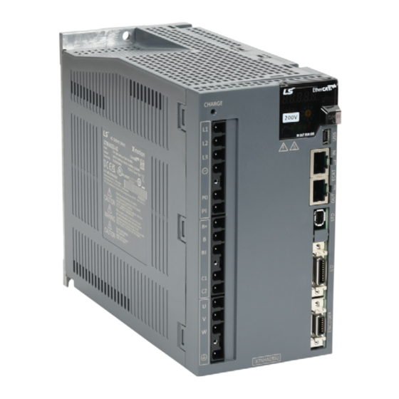
iX7NH Series AC Servo Drive
AutomationDirect Foreword
This QuickStart Guide is designed to get an iX7NH servo system installed and running quickly.
This AutomationDirect Guide is a supplement to the LS Electric iX7NH User Manual. This Guide
does not replace the manufacturer's User Manual. For advanced features or options required
by your application, you may still need to refer to the User Manual. Download and reference
both this QuickStart Guide and the iX7NH User Manual when commissioning an iX7NH servo
system.
This quickstart guide will get your iX7NH drive configured and commissioned using Drive CM.
This is helpful for:
• For further EtherCAT commissioning help, see AutomationDirect's LS Electric Interactive PLC
Guide available at
• For further Modbus TCP commissioning, see the iX7NH Modbus TCP Communications Guide.
A note on Part Numbers: LS Electric servo parts sold by AutomationDirect have part numbers
that end with "-AD". This suffix signifies special packaging and labeling for AutomationDirect.
All the LS servo products with the "-AD" function and behave exactly the same as the standard
LS Electric parts. Please note that when reading the LS electric User Manual or using the Drive
CM software, the "-AD" will NOT appear in any part numbers. For example, AutomationDirect
part iX7NHA004U-AD is just iX7NHA004U in the LS Electric documentation.
NOTE: EtherCAT® is a registered trademark and patented technology, licensed by Beckhoff
Automation GmbH, Germany.
Quick Start Guide
1st Edition, December 4th, 2023
https://cdn.automationdirect.com/static/helpfiles/ls_plc/Content/Home.htm
Modbus TCP
Advertisement
Table of Contents

Related Manuals for LS ELECTRIC iX7NH Series


Summary of Contents for LS ELECTRIC iX7NH Series
- Page 1 All the LS servo products with the “-AD” function and behave exactly the same as the standard LS Electric parts. Please note that when reading the LS electric User Manual or using the Drive CM software, the “-AD” will NOT appear in any part numbers. For example, AutomationDirect part iX7NHA004U-AD is just iX7NHA004U in the LS Electric documentation.
-
Page 2: Table Of Contents
Series Servo System Overview ........ -
Page 3: Ix7Nh Series Servo System Overview
Series AC Servo Drives Quick Start Guide iX7NH Series Servo System Overview Warnings and Cautions WARNING: Install both the servo drive and the servo motor before performing any wiring. WARNING: Before wiring or inspecting, turn off the power, wait 15 minutes, make sure the charge lamp is off, and check the voltage. -
Page 4: Installation
Series AC Servo Drives Quick Start Guide Installation Ambient Installation Conditions The iX7NH Servo and APM/APMC motors should be installed under the environmental conditions detailed below. Exceeding these conditions risks damage to the equipment. Condition Requirement Notes Install a cooling fan on the control panel for Operating Temperature 0–50°C [32–122 °F]... -
Page 5: Quick Start Instructions
Series AC Servo Drives Quick Start Guide Quick Start Instructions To verify your servo components and motor/drive wiring as quickly as possible, please follow the steps below. These basic instructions will quickly get the motor spinning (verifying that parts and power wiring are correct). - Page 6 Series AC Servo Drives Quick Start Guide Step 3: Connect the PC to the Drive Substep Task Using a standard USB A to USB mini-B cable (such as SV2-PGM-USB15, MOSAIC-CSU, etc.), connect the PC to the Drive. Start Drive CM software.
- Page 7 Series AC Servo Drives Quick Start Guide Step 6: Jog the Motor Substep Task Remove power from the drive. Ensure that there is nothing attached to the motor shaft. Initial motion testing should always be done with the motor uncoupled.
-
Page 8: First Time Inspection
Series AC Servo Drives Quick Start Guide First Time Inspection Ensure your servo motor and drive match capacity. iX7NH Servo Drive Compatible Motors Input Power Drive Voltage Rating Non-braking Braking Part Number Explanation APMC-FBL01AMK-AD APMC-FBL01AMK2-AD The three-digit number in... -
Page 9: Apmc And Apm Servo Motor
Part Number Explanation The motor part number is defined by several of the digits in the middle. Note that the “-AD” simply represents special packaging for AutomationDirect. These are standard LS Electric Parts. APM(C)-FxxyyzMK(2)-AD • XX = the frame size: •... -
Page 10: Basic Inspection
Series AC Servo Drives Quick Start Guide Basic Inspection Perform periodic inspections to maintain your equipment, as well as inspections before operation of the servo and motor. Inspection Task Periodically check to confirm the screws are securely tightened. This includes the screws in the servo drive, the connection screws between the motor shaft and the machine, and the connection screws between the terminal block and machine. -
Page 11: System Wiring
Series AC Servo Drives Quick Start Guide System Wiring Pre-made Motor Cables Motor connections utilize premade cables available in normal flex or robotic flex specifications. Cables are available for any iX7NH drive and motor size 100W–3.5 kW but are model dependent (brake cables are only applicable for brake motors). - Page 12 Series AC Servo Drives Quick Start Guide Cable Type Illustration Drive Side Connector Motor Side Connector Motor Power and Brake Cable (FE, FF motors) Motor Side Connector Drive Side Connector Motor Power and Brake Cable (FE, FF motors) APCS-L7NCN1T-AD, APCS-L7NCN1T01-AD, APCS-L7NCN1T015-AD, APCS-L7NCN1T02-AD Drive I/O Cables You can download a printable terminal label (“I/O Breakout Template”) at...
-
Page 13: Names And Functions Of Analog Inputs And Outputs
Terminal Assignments and Wire Colors CAUTION: Terminal assignments are different for every LS drive series. Use this terminal assignment chart with iX7NH series drives ONLY. Using terminal charts from other LS series drives will result in incorrect wiring that will damage your equipment. -
Page 14: General Wiring Overview
Series AC Servo Drives Quick Start Guide General Wiring Overview Example System Configuration NOTE: 100W to 2.2 kW 230VAC systems can use a single-phase supply. Any 2 of R,S,T can be used. See “iX7NH Servo Drive” on page 8 for notes on motor sizes that need derating when using single-phase power. -
Page 15: Main Power Connection Wiring
Series AC Servo Drives Quick Start Guide Main Power Connection Wiring NOTE: Single-phase can use any two wires of R, S, or T. Ensure C1 and C2 are powered as well. Drive Specification 400W 1-phase 115V/230V, 3-phase 230V 750W–2.2 kW 1-phase (with derating) or 3-phase 230V 3.5 kW... - Page 16 Series AC Servo Drives Quick Start Guide NOTE: To connect a power or motor connector, use the provided spring cage release tool (IX7- CON-C) or flat-head screwdriver to clear the opening as shown below. Insert the core wire into the hole and pull out the spring opener or flat-head screwdriver to complete connection.
-
Page 17: I/O Connection Wiring Diagram With Default Functions
Series AC Servo Drives Quick Start Guide I/O Connection Wiring Diagram with Default Functions I/O Connection wiring diagram is shown below. For a printable terminal label, go to: https://www.automationdirect.com/pn/APCS-L7NCN1T-AD. See “Terminal Assignments and Wire Colors” on page 13 for terminal assignments. - Page 18 Series AC Servo Drives Quick Start Guide Drive Node Address Setting The iX7NH includes a Modbus TCP Server feature. For Modbus TCP communications to the drive the two rotary dials need to be addressed to node 98 or 99. Node 99 allows access to the built-in webserver in the drive. For...
- Page 19 Series AC Servo Drives Quick Start Guide Digital Outputs 1) You can set the output to contact A (normally open) or Contact B (normally closed). 2) You can assign each output contact to one of 11 output functions. 3) For more information on signal assignment and change of the output contact, refer to the User Manual, section 6.2 “Input/Output Signals Setting.”...
- Page 20 Series AC Servo Drives Quick Start Guide STO Wiring The iX7NHA Safe Torque Off circuit is designed to meet Safety Category 3, Safety integrity level 2 (SIL 2), Performance level d(PL d). ESTOP STO1+ 24VDC S21 S22 STO1- Safety relay...
-
Page 21: I/O Wiring And Option Details For The Analog Input
Series AC Servo Drives Quick Start Guide I/O Wiring and Option Details for the Analog Input 1) For information on how to operate the analog input signal, refer to the User Manual, section 6.9 “Torque Limit Function”. 2) The range of the analog input signal is -10V to 10V. -
Page 22: Led Display
Series AC Servo Drives Quick Start Guide LED Display The LED status display can contain a variety of information, including the status of the drive’s operating state, digital inputs, digital outputs, alarms, and warnings. Please refer to section 4.2 of the User Manual to see details of using the display on the front of the drive to monitor drive status. -
Page 23: Drive Cm Software
Drive CM Software AutomationDirect Foreword The LS Electric Drive CM software does not include “Are you sure?” types of warnings. When you make a change in the SW it takes place immediately in the drive, even settings that initiate motion. - Page 24 Series AC Servo Drives Quick Start Guide Step 2 Connect the servo drive USB port to the PC USB port using a standard USB-A to USB-mini-B cable. Some cables available from AutomationDirect include: USB-A to USB-mini-B Cables SV2-PGM-USB15 Drive CM...
-
Page 25: Using The Drive Cm Software
Series AC Servo Drives Quick Start Guide Using the Drive CM Software There are two main working areas in Drive CM. The Main Window (larger, left) is mostly used for setup and configuration. The Auxiliary Window (smaller, right) has more dynamic operations available. Both areas can be viewed simultaneously for maximum usefulness. - Page 26 Series AC Servo Drives Quick Start Guide Toolbar Functions Icon Function Displays In Trace/Trigger Monitor (Scope) Cyclic Monitor (System Data View) Motor Encoder Setup (no configuration needed for auto-identifiable FBL/FCL motors) Main Window General Configuration Setup Fault Configuration Controls Loop (Manual Tuning)
-
Page 27: I/O Configuration
Series AC Servo Drives Quick Start Guide I/O Configuration Digital Inputs Use the following parameters to configure Digital Input functionality or use the Digital Input window in Drive CM directly to make changes. The software provides a very easy way to change the DI functions using the digital input icon (quickest and easiest method for configuration). - Page 28 Series AC Servo Drives Quick Start Guide Digital Input Codes See section 3.5.1 and 6.2.1 in the User Manual for more information about DI codes. Drive CM is the easiest way to edit the DI codes - including changing the NO and NC settings. Either enter values directly into Parameters 0x2200–0x2205 (Object Dictionary’s I/O tab) or use the pulldown lists after...
-
Page 29: Digital Outputs
Series AC Servo Drives Quick Start Guide Digital Outputs Use the following parameters to configure Digital Output functionality or use the Digital Output window in Drive CM directly to make changes. All three digital outputs are configurable. The software provides a very easy way to change the DO functions using the digital output icon (the quickest and easiest method of configuration). -
Page 30: I/O Connection - Analog Torque Input
Series AC Servo Drives Quick Start Guide Digital Output Codes See section 3.5.1 and 6.2.2 in the user manual for more information about DO codes. Drive CM is the easiest way to edit the DO Codes, including changing the NO and NC settings. Either enter values directly into Parameters 0x2210–0x2212 (Object Dictionary’s I/O tab) or use the pulldown lists after... -
Page 31: Setup Wizard
Series AC Servo Drives Quick Start Guide Setup Wizard Below is a simple walk through of minimal settings to establish EtherCAT control. Other object configuration settings may be required for your specific needs. See the User Manual for details. - Page 32 Series AC Servo Drives Quick Start Guide Step 3: Motor Rotation Direction Substep Task Click Next to set the Rotation Direction. This sets which motor direction is considered positive or negative. If this isn’t known, it can be set later in 0x2004 (in the Object Dictionary \ Basic tab).
- Page 33 Series AC Servo Drives Quick Start Guide Step 4: Set Electronic Gear Ratio Substep Task On the Electronic Gear Ratio screen, enter the resolution of the motor’s encoder (19-bit=524288 ppr) (Object 6091:1). Also enter the number of pulses (User Units) you want to equal one shaft rotation (Object 6091:2).
- Page 34 Series AC Servo Drives Quick Start Guide Step 5: Set Emergency Stop and Dynamic Brake Control Substep Task For initial setup and testing, choose the defaults for these settings on the Emergency Stop Configuration and Dynamic Brake Control Mode screen. More information can be found in the User Manual under Dynamic Brake Control Mode (0x2012) and Emergency Stop Configuration (0x2013).
- Page 35 Series AC Servo Drives Quick Start Guide Step 7: Set the Torque Limit Function Substep Task Set the Torque Limit Function. Select a method for limiting the torque (0x2110) applied to the load while the motor is trying to attain commanded speed and final position.
- Page 36 Series AC Servo Drives Quick Start Guide Step 8: Set Signals Related to Position Control Substep Task Configure the “In Position” signals on the Signals Related to Position Control screen if you will use Digital Outputs INPOS1 and INPOS2.
- Page 37 Series AC Servo Drives Quick Start Guide Step 10: Set the I/O Signal Setting Substep Task Configure Inputs 1 through 6 as needed for your application. Defaults are shown below. Click Next to Go to Digital Output in the Setup Wizard.
- Page 38 Series AC Servo Drives Quick Start Guide Step 12: Set Homing Method Setting Substep Task On the Homing Method Setting screen, select the Homing method appropriate for your application. For initial setup and testing, choose the defaults for these settings. Refer to section 5.6 Homing in the User Manual for more details.
Need help?
Do you have a question about the iX7NH Series and is the answer not in the manual?
Questions and answers