Table of Contents
Advertisement
Quick Links
The Best Choice for the Most Benefit!
We are committed to providing premium benefits to all of our customers.
Xmotion
Xmotion
Safety Precautions
Read all safety precautions before using this
product.
After reading this manual, store it in a readily
accessible location for future reference.
AC SERVO DRIVE
L7NHF Series
User Manual
Ver1.2
Advertisement
Table of Contents

Subscribe to Our Youtube Channel
Related Manuals for LS ELECTRIC L7NHF Series


Summary of Contents for LS ELECTRIC L7NHF Series
- Page 1 The Best Choice for the Most Benefit! We are committed to providing premium benefits to all of our customers. AC SERVO DRIVE L7NHF Series Xmotion Xmotion User Manual Ver1.2 Safety Precautions Read all safety precautions before using this product.
- Page 3 Introduction Introduction Greetings! Thank you for choosing L7NHF Series product. The user manual describes how to correctly use this product and matters for which to exercise caution. Failure to comply with the guidelines outlined in this manual may cause personal injury or damage to the product.
- Page 4 Introduction Safety precautions are categorized as either Warning or Caution, depending on the severity of the consequences. Precautions Descriptions Failure to comply with the guidelines may cause serious injury or death. Danger Failure to comply with the guidelines may cause personal injury or property Caution damage.
- Page 5 Introduction Installation Precautions Store and operate this product under the following environmental conditions. Conditions Environment Servo Drive Servo Motor Operating 0 ~ 50 ℃ 0 ~ 40 ℃ temp. -20 ~ 65 ℃ -10 ~ 60 ℃ Storage temp. Operating humidity 90% RH or lower (no condensation)
- Page 6 Introduction Wiring Precautions Caution Always use an AC 200-230 V power input for the servo drive. Always connect the servo drive to a ground terminal. Do not connect a commercial power supply directly to the servo motor. ...
- Page 7 Introduction Usage Precautions Caution Install an emergency cut-off circuit which can immediately stop operation in an emergency. Reset the alarm only when the servo is off. Be warned that the system restarts immediately if the alarm is reset while the servo is on. ...
- Page 8 Introduction Repair/Inspection Precautions Caution Before performing repair or inspection, turn off the power, wait at least 15 minutes, make sure that the charge lamp has gone off, and check the voltage. Enough voltage may remain in the electrolytic condenser after the power is off to cause an electric shock.
-
Page 9: Table Of Contents
Table of Contents Table of Contents 1. Product Configuration ......1-1 1.1 Product Verification..............1-1 1.2 Product Specifications ............1-2 1.3 Component Names..............1-3 1.3.1 Servo Drive Component Names............ 1-3 1.3.2 Servo Motor Part Names ............... 1-7 1.4 Example of System Configuration ......... 1-8 2. - Page 10 Table of Contents 2.7 Second Encoder (Encoder 2) ..........2-32 2.8 Wiring for Safety Function Signals (STO) ......2-33 2.8.1 Names and Functions of Safety Function Signals ...... 2-33 2.8.2 Example of Connecting Safety Function Signals ......2-34 2.8.3 Bypass Wiring of Safety Function Signals ........2-35 2.9 Wiring for EtherCAT Communication Signals ......
- Page 11 Table of Contents 5.2.2 Digital Output Signal Assignment ..........5-8 5.2.3 Assignment of Analog Output Signals ......... 5-10 5.2.4 Use of User I/O ................5-14 5.3 Electric Gear Setup ............. 5-18 5.3.1 Electric Gear ................5-18 5.3.2 Example of Position Operation Electric Gear Setting ....5-21 5.4 Velocity Control Settings ............
- Page 12 Table of Contents 7.3 Manual Gain Tuning ...............7-6 7.3.1 Gain Tuning Sequence ..............7-6 7.4 Vibration Control ..............7-10 7.4.1 Notch Filter .................. 7-10 7.4.2 Adaptive Filter ................7-11 7.4.3 Vibration Suppression Filter ............7-12 8. Procedure Function ........ 8-1 8.1 Manual Jog Operation ............8-2 8.2 Program Jog Operation ............8-2 8.3 Deleting Alarm History ............8-4...
- Page 13 13. Test Drive ..........13-1 13.1 Preparation for Operation ............ 13-2 13.2 Test Drive Using TwinCAT System Manager ....... 13-4 13.3 Test Drive Using LS ELECTRIC PLC (XGT + PN8B) ..13-12 14. Appendix ..........14-1 14.1 Firmware Update ..............14-1 14.1.1 Use of USB OTG .................
- Page 14 Table of Contents...
-
Page 15: Product Configuration
1. Product Configuration Product Configuration Product Verification 1. Check the name plate to verify that the product received matches the model ordered. Does the servo drive's name plate match? Does the servo motor's name plate match? 2. Check the product components and options. ... -
Page 16: Product Specifications
1. Product Configuration Product Specifications L7NHF Series Product Type L7 NHF A 010 U AA Communication/Drive Series Name Input voltage Capacity Encoder Option Type Blank: StandardMar NHF: Network Type 010 : 1kW U : Universal ked: L7 Series All In One Type A : 200Vac 035 : 3.5kW... -
Page 17: Component Names
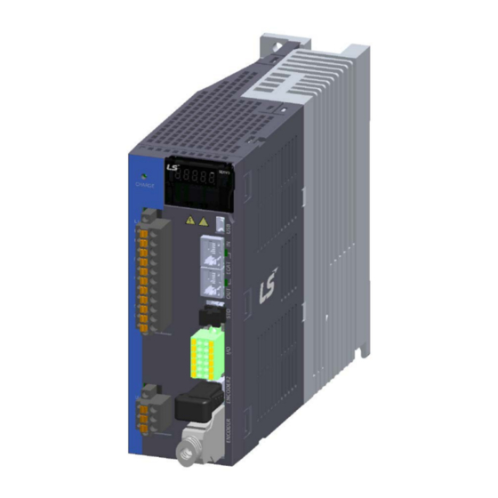
1. Product Configuration Component Names 1.3.1 Servo Drive Component Names L7NHF Drive (1 kW) Analog monitor connector Display Connector to check analog output signals. Shows drive status, alarms, etc. CHARGE lamp Node address setting switch Lights on when the main circuit Switch to set the node address of the drive. - Page 18 1. Product Configuration L7NHF Drive (3.5kW) Analog monitor connector Connector to check analog output signals. Node address setting switch Switch to set the node address of the drive. You can set the node addresses from 0 to 99. USB connector (USB) This connector is used to communicate with a PC.
- Page 19 1. Product Configuration L7NHF Drive (5kW) Analog monitor connector Connector to check analog output signals. Node address setting switch Switch to set the node address of the drive. You can set the node addresses from 0 to 99. USB connector (USB) This connector is used to communicate with a PC.
- Page 20 1. Product Configuration L7NHF Drive (7.5kW) Analog monitor connector Connector to check analog output signals. Node address setting switch Switch to set the node address of the drive. You can set the node addresses from 0 to 99. USB connector (USB) This connector is used to communicate with a PC.
-
Page 21: Servo Motor Part Names
1. Product Configuration 1.3.2 Servo Motor Part Names •80 Flange of Lower (L series) Encoder connector Power connecotor Shaft Flange Frame Housing Encoder Cover • 130 Flange or Higher Motor Connector Encoder Connector Encoder Cover Shaft Flange Frame Housing Bearing Cap... -
Page 22: Example Of System Configuration
1. Product Configuration Example of System Configuration The figure below shows an example of system configuration using this drive. Power Three-phase AC 220 V Upper Device R S T Molded-case Circuit Breaker It is used to protect power line. It turns off the circuit if overcurrent flows. -
Page 23: Wiring And Connection
2. Wiring and Connection Wiring and Connection Servo Motor Installation 2.1.1 Operating Environment Items Environmental conditions Precautions Ambient Consult our technical support team to customize the product if the 0 ∼ 40[℃] temperature temperatures in the installation environment are outside this range. Ambient 80[%] RH or lower Do not operate this device in an environment with steam. -
Page 24: Motor Connection
2. Wiring and Connection 2.1.3 Motor Connection Servo Motor Directly connecting the motor to a commercial power supply may burn the motor. Make sure to connect it with the specified drive before using it. Connect the ground terminals of the motor to either of the two ground terminals inside the drive, and attach the remaining terminal to the type-3 ground. -
Page 25: Load Device Connection
2. Wiring and Connection 2.1.4 Load Device Connection For coupling connections: Ensure that the motor shaft and load shaft are aligned within the tolerance range. 0.03 ㎜ or below (peak to peak) Load shaft Motor shaft 0.03 ㎜ or below (peak to peak) ... -
Page 26: Servo Drive Installation
2. Wiring and Connection Servo Drive Installation 2.2.1 Installation and Usage Environment Environmental Items Precautions conditions Caution Ambient 0∼50[℃] Install a cooling fan on the control panel for ventilation and to temperature maintain the temperature within the range. Caution Moisture developed inside the drive due to ice formation or Ambient 90% RH or lower condensation during a prolonged period of inactivity may... -
Page 27: Installation With The Control Panel
2. Wiring and Connection 2.2.2 Installation with the Control Panel Comply with the spacing standard specified in the following figures when installing with the control panel. 40mm 100mm or more or more 10mm 10mm 10mm 10mm or more or more or more or more 40mm... -
Page 28: Internal Block Diagram Of The Servo Drive
2. Wiring and Connection Internal Block Diagram of the Servo Drive 2.3.1 L7NHF Drive Block Diagram (L7NHFA010U and L7NHFA035U) Note 1) Note 2) Note 3) Diode Thermistor IGBT 3-phase Power Input Input Current Regeneration brake resistor sensor AC200~230V Thermistor Chage Lamp Thermistor Note 4) -
Page 29: L7Nhf Drive Block Diagram (L7Nhfa050U And L7Nhfa075U)
2. Wiring and Connection 2.3.2 L7NHF Drive Block Diagram (L7NHFA050U and L7NHFA075U) (Note 2) (Note 1) External regeneration brake resistor mounted separately Diode IGBT (Note 3) 3-phase Power Input Current sensor AC200~230V Thermistor Chage Lamp T1 T2 Thermistor (Note 4) IGBT U and V DC voltage... -
Page 30: Power Supply Wiring
2. Wiring and Connection Power Supply Wiring Ensure that the input power voltage is within the acceptable range. Caution Excessive voltage damages the drive. If a commercial power supply is connected to U, V and W terminals of the drive, the drive may be damaged. -
Page 31: Power Supply Wiring Diagram
2. Wiring and Connection 2.4.1 Power Supply Wiring Diagram Power Supply Wiring Diagram (L7NHFA010U and L7NHFA035U) AC 200~230[V] Servo drive R S T NOTE 1) Main Main DC reactor PO PI NOTE 3) Encoder Alarm+ Alarm- External NOTE 2) regenerati ve resistor Note 1) It takes approximately 1 to 2 seconds until an alarm signal is output after you turn on the main power. - Page 32 2. Wiring and Connection Power Supply Wiring Diagram (L7NHFA050U to L7NHFA075U) AC 200~230[V] Servo drive R S T NOTE 1) Main Main DC reactor PO PI NOTE 3) Encoder Alarm+ Alarm- External NOTE 2) regenerati ve resistor Note 1) It takes approximately 1 to 2 seconds until an alarm signal is output after you turn on the main power. Press and hold the main power ON switch for at least 2 seconds.
-
Page 33: Power Input Sequence
2. Wiring and Connection 2.4.2 Power Input Sequence Power Input Sequence For wiring of the main power, use a magnetic contactor for the main circuit power as shown in Section 2.4.1, "Power Supply Wiring Diagram." Set the magnetic contactor to be turned off simultaneously with an alarm occurrence in the external sequence. -
Page 34: Power Circuit Electrical Component Standards
2. Wiring and Connection 2.4.3 Power Circuit Electrical Component Standards L7NHFA010U ~ L7NHFA075U L7NHFA010U L7NHFA035U L7NHFA050U L7NHFA075U Model Name 30A Frame 15A MCCB 30A Frame 30A 50A Frame 40A 50A Frame 50A (NFB) (ABE33b/30) (ABE53b/40) (ABE53b/50) (ABE33b/15) Noise Filter TB6-B010LBEI(10A) TB6-B030NBDC(30A) TB6-B040A (40A) - Page 35 2. Wiring and Connection L7NHFA010U Wire strip 7~10[mm] Weidmuller SD 0.6×3.5×100 M4 : 1.2 [N·m] Weidmuller SD 0.6x3.5x100 M4 : 1.2[N.m] 2-13...
- Page 36 2. Wiring and Connection L7NHFA035U Wire strip 7~10[mm] Weidmuller SD 0.6x3.5x100 M4 : 1.2[N.m] 1) For information on wiring to BLF 5.08 and BLZ7.62HP Series connectors, refer to the above procedures. 2) Insert electric wire into insert hole with upper locking screw loosened, and use applicable flathead (-) driver for each model to fully tighten screw to 0.4-0.5 N·m.
- Page 37 2. Wiring and Connection L7NHFA050U NC: Screw that fastens the lead terminal of internal regenerative resistor Terminal screw: M4 Tightening torque: 1.2 N m Terminal screw: M4 Tightening torque: 1.2 N m Terminal screw: M4 Tightening torque: 1.2 N m Otherwise, insufficient torque of locking screw may cause vibration-induced disconnection, system malfunction and contact-induced fire accident.
- Page 38 2. Wiring and Connection L7NHFA075U NC: Screw that fastens the lead terminal of internal regenerative resistor Terminal screw: M5 Tightening torque: 3.24 N m Terminal screw: M5 Tightening torque: 3.24 N m Terminal screw: M4 Tightening torque: 1.2 N m Otherwise, insufficient torque of locking screw may cause vibration-induced disconnection, system malfunction and contact-induced fire accident.
-
Page 39: Regeneration Brake Resistor Options
2. Wiring and Connection 2.4.4 Regeneration Brake Resistor Options Item Product Model Name Applicable Specifications Name Drive Resist Regenerati APC-300R30 L7NHFA010U ance ve resistor Resist Regenerati APC-600R30 L7NHFA035U ance ve resistor L7NHFA050U (4P) Resist Regenerati APC-600R28 ance ve resistor L7NHFA075U (4P) IRM2000-3.3Ω... -
Page 40: Wiring For Input/Output Signals
2. Wiring and Connection Wiring for Input/Output Signals I/O Connector Specifications: DFMC 1.5/6-STF-3.5 (PHOENIX) 11 : DOCOM 12 : DO3 9 :DO2 10 : DO1 7 : DI6 8 : DI5 5 : DI4 6 : DI3 4 : DI1 3 : DI2 1 : DICOM 2 : FG... -
Page 41: Names And Functions Of Digital Input/Output Signals
2. Wiring and Connection 2.5.1 Names and Functions of Digital Input/Output Signals Names and Functions of Digital Input Signals (I/O Connector) Assignm Name Details Function Number DICOM DC 24V DC 24V INPUT COMMON Positive The actuator stops the servo motor to (CCW) prevent it from moving beyond the motion Rotation... - Page 42 2. Wiring and Connection Names and Functions of Digital Output Signals Name Assignment Details Function Number BRAKE Brake Outputs brake control signal. ALARM Servo Alarm Outputs signal when alarm occurs. This signal is output when the main power is established and the Servo Ready preparations for servo operation are complete.
-
Page 43: Names And Functions Of Analog Input/Output Signals
2. Wiring and Connection 2.5.2 Names and Functions of Analog Input/Output Signals Names and Functions of Analog Output Signals (Analog Monitoring Connector) Name Details Function Number Analog Monitor output (AT NC Axis in case of - 10V~+10V signal 신호면 AT NC Axis 10) AMON1 Analog Monitor 1 Analog Monitor output (AT NC Axis in case of -... -
Page 44: Examples Of Input/Output Signal Connection
2. Wiring and Connection 2.5.3 Examples of Input/Output Signal Connection Examples of Digital Input Signal Connection Caution 1. You can set the input contact to contact A or contact B, based on the characteristics of individual signals. 2. You can assign each input contact to one of 15 functions. 3. - Page 45 2. Wiring and Connection Example of Connecting Digital Output Signals Caution 1. You can set the output contact to contact A or contact B, based on the characteristics of individual signals. 2. You can assign each output contact to one of 11 output functions. 3.
- Page 46 2. Wiring and Connection Examples of Connecting Analog Output Signals Caution 1. Refer to "5.2.3 Assignment of Analog Output Signals" for signal settings and scale adjustment. 2. The range of analog output signals is -10V to 10V. 3. The resolution of analog output signal is 12 bits. 4.
-
Page 47: Input/Output Signals Configuration Diagram
2. Wiring and Connection 2.5.4 Input/Output Signals Configuration Diagram Digital input Digital output DC 24[V] or -24[V] (DO1) +24V IN BRAKE 3.3kΩ (DI1) (DO2) ALARM (DI2) (DI3) HOME (DO3) READY (DI4) STOP (DI5) PCON (DI6) GAIN2 GND 24 ZSPD INPOS1 PROBE1 TLMT PROBE2... -
Page 48: Wiring Of Encoder Signal (Encoder)
2. Wiring and Connection Wiring of Encoder Signal (ENCODER) ENCODER Connector Model: 10114-3000VE (3M) 2.6.1 Quadrature Encoder Signaling Unit Wiring APCS-E AS Cable AWG24 7Pair Twisted AWG24 7Pair Twisted Shield Wire Shield Wire Servo Motor Servo Motor Servo Drive Servo Drive Encoder Encoder... - Page 49 2. Wiring and Connection APCS-E BS Cable AWG24 7Pair Twisted AWG24 7Pair Twisted Servo Motor Servo Motor Servo Drive Servo Drive Shield Wire Shield Wire Encoder Encoder Cable Connector Cable Connector (ENCODER) (ENCODER) Maker – 3M Maker – 3M 10314-52A0-008 10314-52A0-008 Cable...
-
Page 50: Serial Encoder Signaling Unit Wiring
2. Wiring and Connection 2.6.2 Serial Encoder Signaling Unit Wiring APCS-E CS Cable AWG24 4Pair Twisted Servo Drive Servo Motor Shield Wire Encorder Cable Connector (ENCODER) Cable Maker – 3M Connector 10314-52A0-008 Maker - AMP 10114-3000VE 172161-1 Frame 170361-1 ... -
Page 51: Multi-Turn Encoder Signaling Unit Wiring
2. Wiring and Connection APCS-E ES Cable AWG24 4Pair Twisted Servo Motor Servo Drive Shield Wire Encorder Cable Connector (ENCODER) Maker – 3M 10314-52A0-008 10114-3000VE Connector Frame Tyco Connector (7Ciruits) 2.6.3 Multi-Turn Encoder Signaling Unit Wiring APCS-E CS1 Cable AWG24 4Pair Twist AWG24 4Pair Twist Servo Motor... - Page 52 2. Wiring and Connection APCS-E DS1 Cable AWG24 4Pair Twist AWG24 4Pair Twist Servo Motor Servo Drive Shield Wire Shield Wire BAT+ BAT+ BAT- Encorder Cable Connector Cable Connector (ENCODER) (ENCODER) Maker – 3M Maker – 3M 10314-52A0-008 10314-52A0-008 Cable Cable 10114-3000VE...
-
Page 53: Tamagawa Encoder Signaling Unit Wiring
2. Wiring and Connection 2.6.4 Tamagawa Encoder Signaling Unit Wiring AWG24 2Pair Twist AWG24 2Pair Twist Servo Motor Servo Drive Shield Wire Shield Wire Encorder Cable Connector Cable Connector (ENCODER) (ENCODER) Maker – 3M Maker – 3M 10314-52A0-008 10314-52A0-008 10114-3000VE 10114-3000VE Frame Frame... -
Page 54: Second Encoder (Encoder 2)
2. Wiring and Connection Second Encoder (Encoder 2) Connector specifications - Connector : MUF-PK8K-X - Recommended wiring standards: AWG28 - AWG24 DER2 connector viewed m the front of the drive Wiring and signal name Pin No Signal name Signal name (SSI) (Quadrature) DATA... -
Page 55: Wiring For Safety Function Signals (Sto)
2. Wiring and Connection Wiring for Safety Function Signals (STO) 2069577-1(Tyco Electronics) 2.8.1 Names and Functions of Safety Function Signals Names Function Number +12V For bypass wiring -12V STO1- DC 24V GND STO1+ Blocks the current (torque) applied to the motor when the signal is off. STO2- DC 24V GND STO2+... -
Page 56: Example Of Connecting Safety Function Signals
2. Wiring and Connection 2.8.2 Example of Connecting Safety Function Signals Caution 1. The rated voltage is DC 12 V to DC 24 V. 2. With the contacts of STO1 and STO2 off, the motor output current is blocked. 24 V Power STO1+ Driving Signal Blocking... -
Page 57: Bypass Wiring Of Safety Function Signals
2. Wiring and Connection 2.8.3 Bypass Wiring of Safety Function Signals This drive provides the Mini I/O Bypass connector which has Bypass wiring to be used for the convenience of the user when the STO function is not used. To use the Bypass function, connect the Mini I/O Plug connector as follows. -
Page 58: Wiring For Ethercat Communication Signals
2. Wiring and Connection Wiring for EtherCAT Communication Signals 2.9.1 Names and Functions of EtherCAT Communication Signals EtherCAT IN and EtherCAT OUT Connector Signal Names Line Color Number TX/RX0 + White/Orange TX/RX0 - Orange TX/RX1+ White/Green TX/RX2 - Blue TX/RX2 + White/Blue TX/RX1 -... -
Page 59: Example Of Drive Connection
2. Wiring and Connection 2.9.2 Example of Drive Connection The following figure shows the connection between a master and slave using EtherCAT communication. This is an example of a connection by topology of the basic line type. For an environment with much noise, install ferrite core at both ends of the EtherCAT cable. EtherCAT Position Master... - Page 60 2. Wiring and Connection 2-38...
-
Page 61: Ethercat Communication
3. EtherCAT Communication EtherCAT Communication EtherCAT stands for Ethernet for Control Automation Technology. It is a communication method for masters and slaves that uses Real-Time Ethernet, developed by the German company BECKHOFF and managed by the EtherCAT Technology Group (ETG). The basic concept of EtherCAT communication is that, when a DataFrame sent from a master passes through a slave, the slave inputs the received data to the DataFrame as soon as it receives the data. -
Page 62: Ethercat State Machine
3. EtherCAT Communication 3.1.1 EtherCAT State Machine Init Pre-Operational Boot Safe-Operational Operational The EtherCAT drive has 5 states as shown above, and a state transition is achieved by an upper level controller (master). State Description A state for firmware updates. Only mailbox communication using the FoE (File Boot access over EtherCAT) protocol is available. -
Page 63: Status Led
3. EtherCAT Communication Status LED The LEDs on the EtherCAT ports of this drive indicate the states of the EtherCAT communications and errors, as shown in the following figure. There are 3 green LEDs, L/A0, L/A1, and RUN, and 1 red LED, ERR. - Page 64 3. EtherCAT Communication RUN LED The RUN LED indicates in which state the drive is in the EtherCAT State Machine. LED Status Description The drive is in the Init state. The drive is in the Pre-Operational state. Blinking The drive is in the Safe-Operational state. Single Flash The drive is in the Operational state.
-
Page 65: Data Type
3. EtherCAT Communication Data Type The following table outlines the data types and ranges used in this manual. Codes Description Ranges SINT Signed 8-bit -128 ~127 USINT Unsigned 8-bit 0 ~ 255 Signed 16-bit -32768 ~ 32767 UINT Unsigned 16-bit 0 ~ 65535 DINT Signed 32-bit... - Page 66 3. EtherCAT Communication The setting values of the RxPDO (0x1600) are as follows: SubIndex Setting Value 0x02 (2 values assigned) Bit 31~16(Index) Bit 15~8(Sub index) Bit 7~0(Bit size) 0x6040 0x00 0x10 0x607A 0x00 0x20 This is an example when assigning the Statusword, the Position Actual Value, and the Actual Velocity Value with the TxPDO (0x1A00).
- Page 67 3. EtherCAT Communication Object Dictionary Sync Manager Entity Sync Manager Index Object Contents 0x1C10 0x1C11 0x1C12 0x1C13 Assign Object Mailbox Mailbox RxPDO TxPDO 0x1C12 RxPDO Receive Send (0x1601) (0x1A02) 0x1C13 TxPDO 0x1600 RxPDO RxPDO 0x1601 0x1602 RxPDO 0x1603 RxPDO Mapping Object 0x1A00 TxPDO 0x1A01...
-
Page 68: Synchronization Using The Dc (Distributed Clock)
3. EtherCAT Communication Synchronization Using the DC (Distributed Clock) The Distributed Clock (DC) synchronizes EtherCAT communication. The master and slave share a reference clock (system time) for synchronization, and the slave synchronizes its applications with the Sync0 event generated by the reference clock. The following synchronization modes exist in this drive. You can change the mode with the sync control register. -
Page 69: Cia402 Drive Profile
4. CiA402 Drive Profile CiA402 Drive Profile State machine Start Supplementary State state State changed by the Not ready to Switch on State slave State that can be State (A): Low-level power checked by the master The control power is on; The main power can be turned on. - Page 70 4. CiA402 Drive Profile The state of the State Machine can be switched by bit setting combinations of the Controlword (0x6040), as described in the table below: bits of the Controlword (0x6040) State Machine Command Bit 7 Bit 3 Bit 2 Bit 1 Bit 0 switching...
- Page 71 4. CiA402 Drive Profile Switched on disabled Warning Remote Target reached Internal limit active Operation mode specific Remote ABS position valid Procedure busy...
-
Page 72: Operation Modes
4. CiA402 Drive Profile Operation Modes This drive supports the following operation modes (0x6060): Profile Position Mode(PP) Homing Mode(HM) Profile Velocity Mode(PV) Profile Torque Mode(PT) Cyclic Synchronous Position Mode(CSP) Cyclic Synchronous Velocity Mode(CSV) Cyclic Synchronous Torque Mode(CST) Drive functions supported for each mode are listed in the table below: Operation Modes... -
Page 73: Position Control Modes
4. CiA402 Drive Profile Position Control Modes 4.3.1 Cyclic Synchronous Position Mode Cyclic Synchronous Position (CSP) mode receives the target position (0x607A) that is renewed at every PDO update cycle from the upper level controller to control the position. In this mode, the controller is able to calculate the velocity offset (0x60B1) and the torque offset (0x60B2) that corresponds to the speed and torque feedforwards respectively, and pass them to the drive. - Page 74 4. CiA402 Drive Profile Related Objects Variable Index Name Accessibility Unit Index Type Assignment 0x6040 Controlword UINT 0x6041 Statusword UINT 0x607A Target Position DINT Software Position Limit Number of entries USINT 0x607D Min position limit DINT Max position limit DINT 0x6084 Profile Deceleration...
- Page 75 4. CiA402 Drive Profile Internal Block Diagram of CSP Mode 0x60B1 Velocity Offset [UU/s] Gear Ratio Velocity 0x60B0 0x607A Feed-Forward Position Offset Target Position [UU] [UU] 0x6062 0x60FC Gain 0x210C Position Demand Position Demand Value [UU] Internal Value [pulse] Filter 0x210D Position...
-
Page 76: Profile Position Mode
4. CiA402 Drive Profile 4.3.2 Profile Position Mode Unlike CSP mode, which receives the target position that is renewed at every PDO update cycle from the upper level controller, in Profile Position (PP) mode, the drive generates a position profile internally to operate up to the target position (0x607A) using the profile velocity (0x6081), acceleration (0x6083), and deceleration (0x6084). - Page 77 4. CiA402 Drive Profile Related Objects Variable Index Name Accessibility Unit Index Type Assignment 0x6040 Controlword UINT 0x6041 Statusword UINT 0x607A Target Position DINT Software Position Limit Number of entries USINT 0x607D Min position limit DINT Max position limit DINT 0x607F Maximum Profile Velocity...
- Page 78 4. CiA402 Drive Profile Internal Block Diagram of PP Mode Gear Ratio 0x60B1 0x607D Velocity Offset Software Position 0x607A [UU/s] Limit [UU] Velocity Target Position Feed-Forward [UU] Position 0x6062 0x60FC Gain 0x210C Limit Position Demand Position Demand Value [UU] Internal Value [pulse] Filter 0x210D...
- Page 79 4. CiA402 Drive Profile You can use the following three position commands in Profile Position Mode: Single set point After reaching the target position, the drive sends a completion signal to the upper level controller and receives a new command. ...
- Page 80 4. CiA402 Drive Profile Change Immediately Driving Procedure Velocity Set-point Change immediately Change of Set-point (1) Specify the target position (0x607A). (2) Set the New set point bit to 1 and the Change set immediately bit to 1 to request the position operation.
-
Page 81: Velocity Control Modes
4. CiA402 Drive Profile Velocity Control Modes 4.4.1 Cyclic Synchronous Velocity Mode Cyclic Synchronous Velocity (CSV) mode receives the target velocity (0x60FF) that is renewed at every PDO update cycle from the upper level controller to control the velocity. This mode allows the upper level controller to calculate the torque offset (0x60B2) that corresponds to the torque feedforward and pass it to the drive. - Page 82 4. CiA402 Drive Profile Related Objects Variable Index Name Accessibility Unit Index Type Assignment 0x6040 Controlword UINT 0x6041 Statusword UINT 0x60FF Target Velocity DINT UU/s 0x6084 Profile Deceleration UDINT UU/s 0x6085 Quick Stop Deceleration UDINT UU/s 0x60B1 Velocity Offset DINT UU/s 0x60B2...
- Page 83 4. CiA402 Drive Profile Internal Block Diagram of CSV Mode 0x60B1 0x60FF Velocity Offset Target Velocity [UU/s] [UU/s] 0x606B Velocity Demand Value [UU/s] Processing Acc./Dec. Speed Command Gear Ratio Servo-Loc k Acc. Time 0x2301 Function Motor 0x6091:01 Dec. Time 0x2302 Select 0x2311...
-
Page 84: Profile Velocity Mode
4. CiA402 Drive Profile 4.4.2 Profile Velocity Mode Unlike CSV mode, which receives the target velocity that is renewed at every PDO update cycle from the upper level controller, in Profile Velocity (PV) mode, the drive generates a velocity profile internally up to the target velocity (0x60FF) using the profile acceleration (0x6083) and deceleration (0x6084) in order to control its velocity. - Page 85 4. CiA402 Drive Profile Related Objects Variable Index Name Accessibility Unit Index Type Assignment 0x6040 Controlword UINT 0x6041 Statusword UINT 0x60FF Target Velocity DINT UU/s 0x607F Maximum Profile Velocity UDINT UU/s 0x6083 Profile Acceleration UDINT UU/s 0x6084 Profile Deceleration UDINT UU/s 0x6085...
- Page 86 4. CiA402 Drive Profile Internal Block Diagram of PV Mode 0x60B1 0x60FF Velocity Offset Target Velocity [UU/s] [UU/s] Position 0x606B Limit Velocity Demand Value [UU/s] Processing Acc./Dec. Speed Command Gear Ratio 0x6083 0x607F Servo-Loc k Acc. Time 0x2301 Profile Acc. Maximum Profile Function [UU/s^2]...
-
Page 87: Torque Control Modes
4. CiA402 Drive Profile Torque Control Modes 4.5.1 Cyclic Synchronous Torque Mode Cyclic Synchronous Torque (CST) mode receives the target torque (0x6071) that is renewed at every PDO update cycle from the upper level controller to control the torque. This mode allows the upper level controller to calculate the torque offset (0x60B2) that corresponds to the torque feedforward and pass it to the drive. - Page 88 4. CiA402 Drive Profile 0x606D Velocity Window UINT UU/s 0x606E Velocity Window Time UINT 0x6077 Torque Actual Value 0.1% 0x606C Velocity Actual Value DINT UU/s 0x6064 Position Actual Value DINT 0x6063 Position Actual Internal Value DINT pulse Internal Block Diagram of CST Mode 0x607F Max.
-
Page 89: Profile Torque Mode
4. CiA402 Drive Profile 4.5.2 Profile Torque Mode Unlike CST mode, which receives the target torque that is renewed at every PDO update cycle from the upper level controller, in Profile Torque (PT) mode, the drive generates a torque profile internally up to the target torque (0x6071) by the torque slope (0x6087) in order to control its torque. - Page 90 4. CiA402 Drive Profile 0x606D Velocity Window UINT UU/s 0x606E Velocity Window Time UINT 0x6077 Torque Actual Value 0.1% 0x606C Velocity Actual Value DINT UU/s 0x6064 Position Actual Value DINT 0x6063 Position Actual Internal Value DINT pulse Internal Block Diagram of PT Mode 0x607F Max.
-
Page 91: Homing
4. CiA402 Drive Profile Homing This drive provides its own homing function. The figure below represents the relationship between the input and output parameters for the Homing Mode. You can specify velocity, acceleration, offset, and homing method. Controlword(0x6040) Homing Method(0x6098) Statusword(0x6041) Homing Speeds(0x6099) Homing... -
Page 92: Homing Method
4. CiA402 Drive Profile 4.6.1 Homing Method The drive supports the following homing methods (0x6098): Homing Method Description (0x6098) The drive returns to the home position by the negative limit switch (NOT) and the Index (Z) pulse while driving in the negative direction. The drive returns to the home position by the positive limit switch (POT) and the Index (Z) pulse while driving in the positive direction. - Page 93 4. CiA402 Drive Profile The drive returns to the home position only with the home switch (HOME) while driving in the positive direction. Related Objects Variable Index Name Accessibility Unit Index Type Assignment 0x6040 Controlword UNIT 0x6041 Statusword UINT 0x607C Home Offset DINT...
- Page 94 4. CiA402 Drive Profile Homing Methods 1 and 2 Negative (CW) Positive (CCW) Index pulse Positive limit switch Negative limit switch (POT) (NOT) 0x6099:01 Speed during search for switch 0x6099:02 Speed during search for Zero For homing using the homing method 1, the velocity profile according to the sequence is as follows. See the details below: Homing Method ①...
- Page 95 4. CiA402 Drive Profile Methods 7, 8, 9, and 10 Positive (CCW) Negative (CW) Index pulse Home switch Positive limit switch (POT) 0x6099:01 Speed during search for switch 0x6099:02 Speed during search for Zero For homing using the homing method 7, the velocity profile according to the sequence is as follows. The sequence varies depending on the relationship between the load position and the home switch during homing, which is categorized into three cases as below.
- Page 96 4. CiA402 Drive Profile (2) At the start of homing, when the Home switch is on Homing Method ⑦ Speed Positive Home switch Index Pulse Time Zero search speed (0x6099:02) Switch search speed (0x6099:01) (A) Since the home signal is on, the drive operates at the switch search speed in the direction of the positive home switch (CCW).
- Page 97 4. CiA402 Drive Profile Positive Neg ative Ho me Switch Ho me Switch Ho me Switch Initial driving directio n: Positive (CCW) Neg ative Positive Ho me Switch Ho me Switch Ho me Switch Initial driving directio n: Neg ative (CW) ...
- Page 98 4. CiA402 Drive Profile (1) At the start of homing, when the Home switch is off and the limit is not met during operation Homing Method ⑭ Speed Negative home switch Index Pulse Zero search speed Time (0x6099:02) Switch search speed (0x6099:01) (A) The initial driving direction is negative (CW), and the drive operates at the switch search speed.
- Page 99 4. CiA402 Drive Profile (3) At the start of homing, when the Home switch is off and the limit is met during operation Homing Method ⑭ Speed Negative limit switch Positive home switch Index Pulse Switch search speed (0x6099:01) Time Zero search speed (0x6099:02) Switch search speed...
- Page 100 4. CiA402 Drive Profile Method 28 Negative (CW) Positive (CCW) Home switch Negative limit switch (NOT) 0x6099:01 Speed during search for switch 0x6099:02 Speed during search for Zero The initial driving direction is negative (CW), and the point where the positive home switch is turned on becomes the home position.
- Page 101 4. CiA402 Drive Profile Method 35 Negative (CW) Positive (CCW) Homing operation 0x6040:bit4 The current position at start of homing operation becomes the home position. Use it to change the current position to Home Position based on the needs of the upper level controller. The drive supports homing methods -1, -2, -3, and -4 apart from the standard ones.
- Page 102 4. CiA402 Drive Profile (A) The initial driving direction is negative (CW), and the drive operates at the switch search speed. (B) When the drive hits the negative stopper, it stands by according to the torque limit value (0x2409) and the time setting value (0x240A) during homing using the stopper, then switches the direction.
- Page 103 4. CiA402 Drive Profile Method -3 and -4 Positive (CCW) Negative (CW) Positive Stopper Negative Stopper 0x6099:01 Speed during search for switch 0x6099:02 Speed during search for Zero Homing methods -3 and -4 only use the stopper to perform homing. The velocity profile according to sequence is as follows.
- Page 104 4. CiA402 Drive Profile Method -5 and -6 Negative (CW) Positive (CCW) Home switch Home switch 0x6099:01 Speed during search for switch 0x6099:02 Speed during search for Zero Homing methods -5 and -6 perform homing only by using the stopper. The velocity profile according to sequence is as follows.
- Page 105 4. CiA402 Drive Profile (2) At the start of homing, when the Home switch is off and the limit is met during operation Homing Method Speed Negative Limit switch ON Homing error Time Switch search speed (0x6099:01) (A) The initial driving direction is negative (CW), and the drive operates at the switch search speed. (B) When the negative limit switch is turned on, the drive issues a homing error and decelerates to a stop.
-
Page 106: Touch Probe Function
4. CiA402 Drive Profile Touch Probe Function The touch probe is a function that rapidly captures the position value of the encoder with external input (PROBE 1 and 2) signals or the index (Z) pulse of the encoder. Example of Touch Probe Wafer mapper system of wafer transfer robot (WTR) When wafers are piled up on a wafer stack, the presence of wafers can be determined by scanning the stack once using a mapping sensor. - Page 107 4. CiA402 Drive Profile Related Objects Variable Index Name Accessibility Unit Index Type Assignment 0x60B8 Touch Probe Function UINT 0x60B9 Touch Probe Status UINT 0x60BA Touch Probe 1 Positive Edge Position Value DINT 0x60BB Touch Probe 1 Negative Edge Position Value DINT 0x60BC Touch Probe 2 Positive Edge Position Value...
- Page 108 4. CiA402 Drive Profile Continuous Trigger Mode (0x60B8.1=1, 0x60B8.9=1): In continuous trigger mode, bits 6, 7, 14, and 15 of the touch probe status (0x60B9) toggle (0 1 or 1 0) every time the corresponding input/edge is input. 0x60B8.0 (0x60B8.8) 0x60B8.4...
-
Page 109: Drive Application Functions
5. Drive Application Functions Drive Application Functions Drive Front Panel Analog monitor output connector L/A 0 L/A 1 Node ID Setting switch Display for servo status 7- Segment EtherCAT Communication status and Error status LED 5.1.1 7-Segment for Indicating the Servo Status 7-Segment for indicating the servo status consists of 5 digits as shown below, which are in the order of Digit 1Digit 5 from right to left. - Page 110 5. Drive Application Functions Three digits from Digit 3~1 of the 7-Segment represent the drive status as described below if no servo alarm occurs. In the event of a servo warning occurrence, the warning status display takes precedence over other status. Digit 3~Digit 1 display Status details STO connector not connected...
- Page 111 5. Drive Application Functions Digit5 indicates the status of the EtherCAT State Machine or of the current control mode and servo ON. If the status of the EtherCAT State Machine is prior to the operation state (communication setup process): A preparation status, where a servo operation is not available, indicating that the EtherCAT communication is in progress.
- Page 112 5. Drive Application Functions In the event of a servo alarm occurrence, Digit 5~1 blink with the below display. Digit 2 and Digit 1 represent the alarm code. The servo alarm display takes precedence over other status. Example for Alarm state AL-10 (IPM Fault) ex.
-
Page 113: Input/Output Signals Setting
5. Drive Application Functions Input/Output Signals Setting 5.2.1 Assignment of Digital Input Signals You can set the digital input signal function and input signal level of the I/O connector. As shown in the figure below, you can arbitrarily assign up to 6 input functions, out of 15 functions, to digital input signals 1 - 6 for use: Digital Input Details... - Page 114 5. Drive Application Functions Bits Setting details Setting Assignable Input Signals Signal Input Level Settings Value (0: Contact A, 1: Contact B) 0x00 Not Assigned 14~8 Reserved 0x01 Input Signal Assignments 0x02 0x03 HOME Contact A: The default status is 1 (High). Input 0 (Low) to activate it (Active Low).
- Page 115 5. Drive Application Functions Example of Digital Input Signal Assignment The following table shows an example of assigning input signals. See the setting values for parameters 0x2200~0x2205. DI#1 DI#2 DI#3 DI#4 DI#5 DI#6 HOME STOP PCON GAIN2 (Contact B) (Contact B) (Contact A) (Contact A)
-
Page 116: Digital Output Signal Assignment
5. Drive Application Functions 5.2.2 Digital Output Signal Assignment You can set the digital output signal function and output signal level of the I/O connector. As shown in the figure below, you can arbitrarily assign up to 3 output functions, out of 11 functions, to the digital output signals 1 - 3 for use: Servo Drive Digital Output... - Page 117 5. Drive Application Functions Assigns the digital output signal 1 function and set the output signal level of the I/O connector. Select signals to assign to bits 7~0, and set the signal level to bit 15. Setting Assignable Output Bits Setting details Value Signals...
-
Page 118: Assignment Of Analog Output Signals
5. Drive Application Functions 5.2.3 Assignment of Analog Output Signals Two channels of analog monitor outputs are provided to adjust drive gain or monitor internal status variables. Digital Input Digital Output DO 1 +24V IN (DI1) DI 1 DO 1 (DI2) DI 2 (DI3) - Page 119 5. Drive Application Functions Related Objects Variable Index Name Accessibility Unit Index Type Assignment 0x2220 Analog Monitor Output Mode UINT 0x2221 Analog Monitor Channel 1 Select UINT 0x2222 Analog Monitor Channel 2 Select UINT 0x2223 Analog Monitor Channel 1 Offset DINT 0x2224 Analog Monitor Channel 2 Offset...
- Page 120 5. Drive Application Functions Analog monitor channel 1 select (0x2221) This sets the monitoring variables to be output to analog monitor output channel 1. Setting Value Displayed Items Unit 0x00 Speed feedback 0x01 Speed command 0x02 Speed error 0x03 Torque feedback 0x04 Torque command...
- Page 121 5. Drive Application Functions Setting Example The following shows an example of monitoring ripples during the 1000 rpm operation of a speed feedback signal: Output offset: 0 rpm Output offset: 0 rpm Output offset: 1000 rpm Output offset: 1000 rpm Output scale: 500rpm/V Output scale: 500rpm/V Output scale: 500rpm/V...
-
Page 122: Use Of User I/O
5. Drive Application Functions 5.2.4 Use of User I/O User I/O means some of the I/Os provided by the drive are used for controlling the drive itself and for the user's individual purposes. All contacts provided by the input/output connector (I/O) can be used as the User I/O. - Page 123 5. Drive Application Functions Related Objects Variable Index Name Accessibility Unit Index Type Assignment 0x60FD Digital Inputs UDINT Bits Description NOT (Negative Limit Switch) POT (Positive Limit Switch) HOME (Home Position Sensor Input) 3 to 15 Reserved DI #1(I/O pin 11), 0:Open, 1:Close DI #2(I/O pin 12), 0:Open, 1:Close DI #3(I/O pin 7), 0:Open, 1:Close DI #4(I/O pin 8), 0:Open, 1:Close...
- Page 124 5. Drive Application Functions How to Set the User Output Servo Drive Digital Output (DO1) (DO1) Not assigned Not assigned Upper Level Controller (DO2) (DO2) ALARM+ ALARM+ Digital Output (DO3) RDY+ (0x60FE) GND 24 Set the function of the digital output port to be used as the user output to "Not assigned (setting 0)."...
- Page 125 5. Drive Application Functions They indicate the status of digital outputs. Description of physical outputs Bits Description 0 to 15 Reserved Forced output (0: OFF, 1: ON) of DO #1 (I/O pins 1 and 2) Provided that the relevant bit mask (0x60FE:02.16) is set to 1. Forced output (0: OFF, 1: ON) of DO #2 (I/O pins 17 and 18) Provided that the relevant bit mask (0x60FE:02.17) is set to 1.
-
Page 126: Electric Gear Setup
5. Drive Application Functions Electric Gear Setup 5.3.1 Electric Gear This function allows you to drive the motor by the user unit in which the user intends to give commands. The electric gear function of the drive does not allow the user to utilize the highest resolution of the encoder. - Page 127 5. Drive Application Functions If you input 524288 for the numerator and 1 for the denominator of the electric gear, the movement ratio of the ball screw for a revolution of the motor is set internally. To move the screw by 1 [mm], you only have to input the same value 1 into User Demand Pulse because the unit has been made the same, which provides convenience in entering commands.
- Page 128 5. Drive Application Functions (A) 5000 ppr encoder (B) 19-bit (524288 ppr) encoder 5000*12/10 = 6000 524288*12/10=629145.6 When the electric gear Different commands should be given to the encoders (motor) used for the same is not used distance movement. For a command given in the minimum user unit of 1 um (0.001 mm) Electric Gear Numerator 1 =5000 Electric Gear Numerator 1 =524288 Electric gear...
-
Page 129: Example Of Position Operation Electric Gear Setting
5. Drive Application Functions 5.3.2 Example of Position Operation Electric Gear Setting Ball Screw Load Apparatus specification Pitch: 10mm, Deceleration ratio: 1/1 User Unit 1um(0.001mm) Encoder specification 19-bit (524288 PPR) Load movement 10[mm] = 10000[User Unit] amount/revolution Electric Gear Numerator 1 : 524288 Electric gear setting Electric Gear Denominator 1 : 10000 ... -
Page 130: Velocity Control Settings
5. Drive Application Functions Velocity Control Settings 5.4.1 Smooth Acceleration and Deceleration For smoother acceleration and deceleration during velocity control, you can generate an acceleration/deceleration profile of a trapezoidal or S-curved shape. Here, You can enable S-curve operation by setting the speed command S-curve time to 1 [ms] or higher. The velocity command acceleration/deceleration time (0x2301, 0x2302) is the time needed to accelerate the drive from the zero speed to the rated speed or to decelerate it from the rated speed to the zero speed. -
Page 131: Servo-Lock Function
5. Drive Application Functions 5.4.2 Servo-lock Function During velocity control operation, the servo position cannot be locked even when 0 is entered for the speed command. This is due to the characteristic of velocity control. Here, you can lock the servo position by enabling the servo-lock function select (0x2311). -
Page 132: Position Control Settings
5. Drive Application Functions Position Control Settings 5.5.1 Position Command Filter You can apply filters to position commands to operate the drive more smoothly. For filtering, you can set position command filter time constant (0x2109) using the primary low pass filter and position command average filter time constant (0x210A) using the movement average. - Page 133 5. Drive Application Functions Related Objects Variable Index Name Accessibility Unit Index Type Assignment 0x2109 Position Command Filter Time Constant UINT 0.1ms Position Command Average Filter Time 0x210A UINT 0.1ms Constant 5-25...
-
Page 134: Position Control Signals
5. Drive Application Functions 5.5.2 Position Control Signals As shown in the figure below, if the following error value (i.e., the difference between the position command value input by the upper level controller and the position feedback value) is below the INPOS1 output range (0x2401) and is maintained for the INPOS1 output time (0x2402), the INPOS1 (Positioning completed 1) signal is output. -
Page 135: Settings Related To Torque Control
5. Drive Application Functions Settings Related to Torque Control 5.6.1 Speed Limit Function In torque control mode, the torque command input from the upper level controller controls the torque, but does not control the speed; thus, the apparatus might be damaged due to the exceedingly increased speed by an excessive torque command. -
Page 136: Positive/Negative Limit Setting
5. Drive Application Functions Positive/Negative Limit Setting This function is used to safely operate the drive within the movable range of the apparatus using the positive/negative limit signals of the drive. Be sure to connect and set the limit switch for safe operation. For more information about the settings, refer to 5.2.1 Assignment of Digital Input Signals. -
Page 137: Brake Output Signal Function Setting
5. Drive Application Functions Brake Output Signal Function Setting If the motor stops due to the servo off state or servo alarm during rotation, you can set the velocity (0x2407) and delay time (0x2408) for brake signal output in order to set the output timing. The brake signal is output if the motor rotation velocity goes below the set value (0x2407) or the output delay time (0x2408) has been reached after the servo off command. - Page 138 5. Drive Application Functions Time when the Servo OFF or PWM output Motor alarm occurred is turned off PWM OFF delay time (0x2011) Servo ON/ Load Direction output of Gravity Brake Signal (1) When the brake signal is output before PWM output is turned off You can output the brake signal first before PWM output is turned off to prevent the drop along the vertical axis due to gravity.
-
Page 139: Torque Limit Function
5. Drive Application Functions Torque Limit Function You can limit the drive's output torque to protect the machine. You can set the limit on torque output in torque limit function select (0x2110). The setting unit of torque limit value is [0.1%]. ... - Page 140 5. Drive Application Functions 0x60E0 Positive Torque Limit 0x2111 External Positive Torque Limit Torque Input Torque Ref. Internal + External Torque Limits 0x60E1 Negative (Setting value 3) Torque Limit 0x2112 External Negative Torque Limit Limits the torque value using internal and external torque limits according to the driving direction and the torque limit signal - Positive: 0x60E0 (if PCL signal is not input), 0x2111 (if PCL signal is input) - Negative: 0x60E1 (if NCL signal is not input), 0x2112 (if NCL signal is input)
- Page 141 5. Drive Application Functions 0x6072 Maximum Torque Torque 0x60B2 0x60E0 Feed-forw ard Target Offset Positive [0.1%] Gain 0x210E Torque Limit Filter 0x210F 0x2111 Torque Limit External Positive Velocity Function Torque Limit Limit Speed Control Velocity Function P Gain I Gain Ref.
-
Page 142: Gain Conversion Function
5. Drive Application Functions 5.10 Gain Conversion Function 5.10.1 Gain Group Conversion Use Gain Group 2 Use Gain Group 1 GAIN 2 Sensor Input This is one of the gain adjustment functions and is used to switch between Gain Groups 1 and 2. You can reduce the time required for positioning through gain conversion. - Page 143 5. Drive Application Functions Waiting time and switching time for gain conversion are as follows. Gain Group 1 Gain Conversion Time 1 Gain Group 2 (0x211A) Gain Conversion Waiting Time 1 (0x211C) Position Loop Gain 1 (0x2101) Position Loop Gain 2 (0x2105) Speed Loop Gain 1 (0x2102) Speed Loop Gain 2 (0x2106) Speed Loop Integral Time Constant 1...
-
Page 144: P/Pi Control Switch
5. Drive Application Functions 5.10.2 P/PI Control Switch PI control uses both proportional (P) and integral (I) gains of the velocity controller, while P control uses only the proportional gain. The proportional gain determines the responsiveness of the entire controller, and the integral gain is used to eliminate errors in the steady state. - Page 145 5. Drive Application Functions Related Objects Variable Index Name Accessibility Unit Index Type Assignment 0x2114 P/PI Control Conversion Mode UINT 0x2115 P Control Switch Torque UINT 0.1% 0x2116 P Control Switch Speed UINT 0x2117 P Control Switch Acceleration UINT rpm/s 0x2118 P Control Switch Following Error...
-
Page 146: Dynamic Brake
5. Drive Application Functions 5.11 Dynamic Brake What is dynamic brake? : It is a method of rapidly stopping the motor by causing an electrical short-circuit to the phases of the servo motor. Circuits of to the dynamic brake are integrated into the drive. The drive can apply short-circuits to only two phases or to all three phases depending on the model type. -
Page 147: Regeneration Brake Resistor Configuration
5. Drive Application Functions Related Objects Variable Index Name Accessibility Unit Index Type Assignment 0x2012 Dynamic Brake Control Mode UINT 0x2013 Emergency Stop Configuration UINT 5.12 Regeneration Brake Resistor Configuration Regeneration refers to a phenomenon where kinetic energy of the motor is converted to electric energy and input into the drive because of the high inertia or sudden deceleration of the load driven. -
Page 148: Use Of Internal Regeneration Brake Resistor
5. Drive Application Functions 5.12.1 Use of Internal Regeneration Brake Resistor This drive essentially has internal regeneration brake resistor depending on its capacity. The integrated regeneration brake resistors depending on the drive capacity are as follows: Internal resistor Drive capacity Internal resistor capacity value 40Ω... - Page 149 5. Drive Application Functions Check the internal regeneration brake resistor value (0x200B). Check the regeneration brake resistor capacity (0x200C). 1 KW or less: Basically, the resistor is installed on the rear of the drive heat sink (see the figure below). 3.5 kW - 7.5 kW: It is basically installed inside the drive.
-
Page 150: Use Of External Regeneration Brake Resistor
5. Drive Application Functions 5.12.2 Use of External Regeneration Brake Resistor When using the external regeneration brake resistor for different driving conditions, make sure to observe the order below for configuration. Wiring external regeneration brake resistor Connect the external regeneration brake resistor to the terminals B and B+. Remove the short-circuits of the terminals B and BI (short-circuited at factory setup, 1 kW or less). -
Page 151: Other Considerations
5. Drive Application Functions Set the maximum capacity and use time at the capacity by using the data sheet of the externally installed regeneration brake resistor If there are no specific values provided, set the maximum capacity to a value 5 times the regeneration brake resistor power (0x200C) and the allowed time to 5000[ms](The values may differ according to the general regeneration brake resistor specifications or the regeneration brake resistor value) -
Page 152: Drive Node Address Setting (Addr)
5. Drive Application Functions 5.13 Drive Node Address Setting (ADDR) Set the drive node address. You can verify the set address in the node ID (0x2003). The value of the node setting switch is read just once when the power is turned on. Any subsequently modified settings will only take effect when the power is turned off and then turned on again. -
Page 153: Safety Functions
6. Safety Functions Safety Functions This servo drive has a built-in safe torque off (STO) function to reduce the risks associated with using the machine by protecting people from the dangerous operation of moveable parts. In particular, this function can be used to prevent the dangerous operation of the machine's moveable parts when you need to perform tasks such as maintenance in a danger zone. - Page 154 6. Safety Functions Timing diagram for STO operation Servo ON/OFF Servo OFF Servo ON STO1 Normal STO State STO2 State Motor Supplied 54us with Power EDM Output 12us (Operated with DB Dynamic Brake Relay Control Mode[0x2012] DB Engaged Setting) Disengaged PWM Off Delay Time[0x2011] Setting + 3[ms](DB Hold Time)
- Page 155 6. Safety Functions Timing diagram for STO recovery Servo OFF Servo ON Servo ON/OFF After the servo is turned on, it operates according STO1 Normal to the normal servo ON/ STO State STO2 State OFF timing. 300us Motor Supplied with Power EDM Output Dynamic Brake Relay...
-
Page 156: External Device Monitor (Edm)
6. Safety Functions External Device Monitor (EDM) Monitor output signal is to monitor the state of safety input signal with an external device. Connect it to the terminal for external device monitor of safety device such as safety controller or safety sensor. -
Page 157: How To Verify The Safety Function
6. Safety Functions How to Verify the Safety Function In case the servo drive was replaced prior to starting up the device or during maintenance, make sure to check the details below: When the STO1 and STO2 signals are turned off, check if the drive is in STO status (Bit 31 for digital input (0x60FD) is 1). - Page 158 6. Safety Functions...
-
Page 159: Tuning
7. Tuning Tuning Current Feedback Vol tage Command Torque Speed Position Command Position Speed Torque Command Power Command Control Control Control Motor Encoder Circuit Operation Operation Operation Position Feedback The drive is set to the torque control, velocity control, or position control mode for use, depending on the method of connecting with the upper level controller. -
Page 160: Auto Gain Tuning (Offline Auto Tuning)
7. Tuning Auto Gain Tuning (Offline Auto Tuning) You can automatically set gain according to the load conditions by using the commands generated by the drive itself. The following gain parameters are changed. Inertia ratio, position loop gain, speed loop gain, speed integral time constant, torque command filter time constant, notch filter 3 frequency, and notch filter 4 frequency The entire gains are set higher or lower depending on the setting value of the system rigidity for gain tuning (0x250E). - Page 161 7. Tuning Related Objects Variable Index Name Accessibility Unit Index Type Assignment 0x250E System Rigidity for Gain Tuning UINT 0x2510 Off-line Gaing Tuning Direction UINT 0x2511 Off-line Gain Tuning Distance UINT...
-
Page 162: Automatic Gain Adjustment (On-Line Auto Tuning)
7. Tuning Automatic Gain Adjustment (On-line Auto Tuning) It does not use offline auto tuning that is generated by the drive, but receives a command from an upper level unit to automatically set the parameters related to gains based on system inertia, the rigidity set by the user, and other general rules. - Page 163 7. Tuning Parameters Changed by Tuning Inertia ratio (0x2100), position loop gain 1 (0x2101), speed loop gain 1 (0x2102), speed integral time constant 1 (0x2103), torque command filter time constant 1 (0x2104) Notch filter 3, 4 frequency (0x2507, 0x250A) → Refer to the auto notch setting function ...
-
Page 164: Manual Gain Tuning
7. Tuning Manual Gain Tuning 7.3.1 Gain Tuning Sequence For a cascade-type controller, tune the gain of the velocity controller located at an inner position first, then tune the gain of the position controller located at an outer position. In other words, perform tuning in the order of proportional gain integral gain feedforward gain. The role of each individual gain is as follows. - Page 165 7. Tuning Speed Command Low gain Middle gain High gain Time The higher the speed proportional gain value, the feedback speed’s responsiveness to the command speed becomes better. However, if the value is too high, an overshoot or ringing may occur. In contrast, if the value is too low, the responding speed becomes low, which slows down system operation.
- Page 166 7. Tuning Position Controller Tuning Velocity FeedForward Velocity Feed-forward Gain[0x210C] Velocity Feed-forward Filter Time Constant [0x2100] Velocity Command Command Filter Limit Position Command Filter Current Position Control Time Constant[0x2109] Control Position Loop Gain[0x2101] Loop Position Command Average Filter Time Contant[0x210A] Encoder (1) Proportional gain setting...
- Page 167 7. Tuning (3) Feedforward setting Positional error monitoring Feedforward filter setting possible Set the filter if you want to increase the feedforward value but noise occurs. You can set feedforward to a value from 0% to 100%, which is the deviation ratio of the position command value being entered currently.
-
Page 168: Vibration Control
7. Tuning Vibration Control 7.4.1 Notch Filter The notch filter is a sort of band stop filter that eliminates specific frequency components. You can use a notch filter to eliminate resonant frequency components of an apparatus, which allows vibration avoidance and higher gain setting. This drive provides notch filters in 4 levels, and you can set frequency, width, and depth for each filter. -
Page 169: Adaptive Filter
7. Tuning 7.4.2 Adaptive Filter Using speed feedback signals, the adaptive filter provides real-time analyses of the vibration frequency generated from the load during drive operation, and configures the notch filter automatically to reduce vibration. It can detect vibration frequencies through frequency analysis in order to automatically configure one or two notch filters. -
Page 170: Vibration Suppression Filter
7. Tuning 7.4.3 Vibration Suppression Filter The vibration suppression filter is a function used to reduce vibration generated in the load side. It measures the vibration frequency in the load side using an external sensor, and uses the measurement as object data for the filter. This drive provides a vibration suppression filter in two levels, and you can set the frequency and damping amount for each filter. - Page 171 7. Tuning Related Objects Variable Index Name Accessibility Unit Index Type Assignment 0x2515 Vibration Suppression Filter Configuration UINT Frequency 0x2516 Vibration Suppression Filter 1 UINT 0.1[Hz] 0x2517 Vibration Suppression Filter 1 Damping UINT Frequency 0x2518 Vibration Suppression Filter 2 UINT 0.1[Hz] 0x2519...
- Page 172 7. Tuning 7-14...
-
Page 173: Procedure Function
8. Procedure Function Procedure Function Procedure function is an auxiliary function provided by the drive as described below. It can be executed by the procedure command code (0x2700) and procedure command factor (0x2701). It can be activated by using the servo setting tool. Procedure commands Codes Details... -
Page 174: Manual Jog Operation
8. Procedure Function Manual Jog Operation Jog operation is a function that verifies servo motor operation by velocity control without an upper level controller. Before you start jog operation, confirm the following. The main power is turned on The STO (Safe Torque Off) connector is connected;... - Page 175 8. Procedure Function … 0x2304 0x2305 0x2306 0x2307 0x2304 0[rpm] 500[rpm] 0[rpm] -500[rpm] 0[rpm] Speed Motor Speed Motor Speed Time Motor Speed -500 … 0x2308 0x2309 0x230A 0x230B 0x2308 500[ms] 5000[ms] 500[ms] 5000[ms] 500[ms] Zero Zero Zero Positive Positive Negative Speed Speed Speed...
-
Page 176: Deleting Alarm History
8. Procedure Function Deleting Alarm History This function deletes all the alarm code histories stored in the drive. Alarm histories including the latest alarm history up to the 16th previous alarm are stored. You can check the histories as shown below (0x2702:01~16). The latest alarm is listed in 0x2702:01. - Page 177 8. Procedure Function Related Objects Variable Index Name Accessibility Unit Index Type Assignment Servo Alarm History Alarm code 1(Newest) STRING Alarm code 2 STRING Alarm code 3 STRING Alarm code 4 STRING Alarm code 5 STRING Alarm code 6 STRING Alarm code 7 STRING...
-
Page 178: Automatic Gain Tuning
8. Procedure Function Automatic Gain Tuning For more information, refer to Section 7.1 Auto Gain Tuning. Index Pulse Search Index pulse search is a function used to find the index (Z) pulse position of the encoder and bring the index to a stop. You can use this function to roughly locate a position since it searches for a position using the Velocity Mode. -
Page 179: Absolute Encoder Reset
8. Procedure Function Absolute Encoder Reset This function resets the absolute encoder. The following are the situations where you need to reset the absolute encoder. To set up the apparatus for the first time When an alarm occurs for low voltage of the encoder ... -
Page 180: Instantaneous Maximum Torque Reset
8. Procedure Function Instantaneous Maximum Torque Reset This function resets the instantaneous maximum overload rate (0x2604) to 0. The instantaneous maximum operation overload rate represents the maximum value of the operation overload rate output instantaneously from the drive for the last 15 seconds. It displays the peak load for the last 15 seconds as a percentage of the rated output. -
Page 181: Software Reset
8. Procedure Function Software Reset This function is used to reset the servo drive by means of software. Software reset means a restart of the drive program, which results in an effect similar to re-applying the power. You can use this function in the following cases. ... - Page 182 8. Procedure Function 8-10...
-
Page 183: Full-Closed Control
9. Full-Closed Control Full-Closed Control The full-closed control function is used to read the position feedback signals from a linear encoder and various encoders on the load side. You can configure the desired system and carry out precision position control without being affected by mechanical system errors. Basically, the full-closed control system uses the external position sensor on the load side to carry out position control. - Page 184 9. Full-Closed Control Function Details It carries out position control based on the encoder information from the motor. Since it is rarely affected by the vibrations of the machine, you can raise the Semi-Closed Advantages servo gain to shorten the adjustment time. Control The machine's accuracy can be lowered due to the vibrations of the machine Disadvantages...
-
Page 185: Full-Closed Control Parameter Settings
9. Full-Closed Control Full-Closed Control Parameter Settings You can set the full-closed control parameters in the following order. Setting the full-closed control mode 0x2023 Full-Closed Control Mode Variable Accessi Variable Savin Setting Range Initial Value Unit Assignm Type bility Attribute Power UINT 0 to 2... - Page 186 9. Full-Closed Control C. Entering load encoder information 0x202B Load Encoder Configuration Variable Accessi Variable Savin Setting Range Initial Value Unit Assignm Type bility Attribute Power UINT 0 to 65535 cycling This sets the second encoder, which is attached to the load side. The settings below change depending on the setting of the encoder type 1.
- Page 187 9. Full-Closed Control Setting example) Singleturn 24[bit] / Gray Code / One start bit / Using clock frequency : below 500[kHz] Bits Description (if encoder type is SSI) 0(one start bit) 12~15 0(656.25kHz) D. Setting the load encoder direction 0x2022 Reverse Load Encoder Direction Variable Accessi...
- Page 188 9. Full-Closed Control 0x2026 Denominator of External Encoder Scale Variable Accessi Variable Savin Setting Range Initial Value Unit Assignm Type bility Attribute Power UINT 0 to 2147483647 cycling This sets the numerator/denominator scale for the external encoder to ensure the same scale as the motor encoder, Examples of scale setting methods 1.
- Page 189 9. Full-Closed Control calculated as 2 mm / 4 um = 500 pulses. Number of external encoder pulses x (numerator / denominator) = Number of 500(Number of external encoder pulses) × = 524288(Number of motor encoder pulses 524288 ( Numerator ) Gear ratio setting 500 ( Denominator ) •...
- Page 190 9. Full-Closed Control 0x2028 External Encoder Following Error Reset Variable Initial Accessi Variable Savin Setting Range Unit Assignm Type Value bility Attribute Power UDINT 0 to 10000 Revolution cycling This sets the position error level for the external encoder and the reset range for the error position value.
- Page 191 9. Full-Closed Control Example of setting the dual-feedback filter time constant Shortens the time for position adjustment Increase the size of the dual feedback filter. Weighted value of semi-closed control Weighted value of the motor-side encoder increases. increases. Decrease the size of the dual feedback filter. Vibrations suppressed Weighted value of the load-side encoder Weighted value of full-closed control increases.
- Page 192 9. Full-Closed Control 9-10...
-
Page 193: Object Dictionary
10. Object Dictionary Object Dictionary Object is a data structure which includes parameters, state variables, run commands (procedures), etc. of the drive. S: Only applied in Velocity Mode Parameter address T: Only applied in Torque Mode P: Only applied in position operation Parameter name ALL: Applied in all operation modes 0x3006... -
Page 194: Data Type
10. Object Dictionary 10.1 Data Type The following table outlines the data types and ranges used in this manual. Codes Description Ranges SINT Signed 8-bit -128 ~127 USINT Unsigned 8-bit 0 ~ 255 Signed 16-bit -32768 ~ 32767 UINT Unsigned 16-bit 0 ~ 65535 DINT Signed 32-bit... - Page 195 10. Object Dictionary 0x1001 Error Register Variable Accessibil Variable Setting Range Initial Value Unit Saving Type Assignment Attribute USINT 0x00 The following table shows the error register values for each device. This value is stored in the emergency message. Bits Setting details 0: No error 1: Error occurs...
- Page 196 10. Object Dictionary 0x1010 Store Parameters SubIndex 0 Number of Entries Variable Accessibil Variable Setting Range Initial Value Unit Saving Type Assignment Attribute USINT SubIndex 1 Store all parameters Variable Accessibil Variable Setting Range Initial Value Unit Saving Type Assignment Attribute UDINT 0 to 0xFFFFFFFF...
- Page 197 10. Object Dictionary 0x1011 Restore Default Parameters SubIndex 0 Number of Entries Variable Accessibil Variable Setting Range Initial Value Unit Saving Type Assignment Attribute USINT SubIndex 1 Restore all parameters Variable Accessibil Variable Setting Range Initial Value Unit Saving Type Assignment Attribute UDINT...
- Page 198 10. Object Dictionary 0x1018 Identity Object SubIndex 0 Number of Entries Variable Accessibil Variable Setting Range Initial Value Unit Saving Type Assignment Attribute USINT SubIndex 1 Vendor ID Variable Accessibil Variable Setting Range Initial Value Unit Saving Type Assignment Attribute UDINT 0x00007595 SubIndex 2...
- Page 199 10. Object Dictionary UDINT 0 to 0xFFFFFFFF 0x60710010 PREOP SubIndex 3 Mapping entry 3 Variable Accessibil Variable Setting Range Initial Value Unit Saving Type Assignment Attribute UDINT 0 to 0xFFFFFFFF 0x607A0020 PREOP SubIndex 4 Mapping Entry 4 Variable Accessibil Variable Setting Range Initial Value Unit...
- Page 200 10. Object Dictionary PDO Mapping : Set the Process Data Objects (PDO) to perform real-time data transfer through the CANopen over EtherCAT protocol. This drive can freely map up to 10 objects of PDOs for transmission/reception, respectively. Use 0x1600 - 0x1603 to set the receiving PDO mapping, and 0x1A00 - 0x1A03 to set the transmitting PDO mapping.
- Page 201 10. Object Dictionary SubIndex 5 Mapping Entry 5 Variable Accessibil Variable Setting Range Initial Value Unit Saving Type Assignment Attribute UDINT 0 to 0xFFFFFFFF PREOP SubIndex 6 Mapping Entry 6 Variable Accessibil Variable Setting Range Initial Value Unit Saving Type Assignment Attribute UDINT...
- Page 202 10. Object Dictionary Type Assignment Attribute UDINT 0 to 0xFFFFFFFF 0x60FF0020 PREOP SubIndex 3 Mapping Entry 3 Variable Accessibil Variable Setting Range Initial Value Unit Saving Type Assignment Attribute UDINT 0 to 0xFFFFFFFF 0x60B80010 PREOP SubIndex 4 Mapping Entry 4 Variable Accessibil Variable...
- Page 203 10. Object Dictionary SubIndex 0 Number of Entries Variable Accessibil Variable Setting Range Initial Value Unit Saving Type Assignment Attribute USINT 0 to 10 PREOP SubIndex 1 Mapping Entry 1 Variable Accessibil Variable Setting Range Initial Value Unit Saving Type Assignment Attribute UDINT...
- Page 204 10. Object Dictionary Variable Accessibil Variable Setting Range Initial Value Unit Saving Type Assignment Attribute UDINT 0 to 0xFFFFFFFF PREOP SubIndex 10 Mapping Entry 10 Variable Accessibil Variable Setting Range Initial Value Unit Saving Type Assignment Attribute UDINT 0 to 0xFFFFFFFF PREOP Refer to the description of 0x1600.
- Page 205 10. Object Dictionary UDINT 0 to 0xFFFFFFFF 0x60610008 PREOP SubIndex 7 Mapping Entry 7 Variable Accessibil Variable Setting Range Initial Value Unit Saving Type Assignment Attribute UDINT 0 to 0xFFFFFFFF 0x26010010 PREOP SubIndex 8 Mapping Entry 8 Variable Accessibil Variable Setting Range Initial Value Unit...
- Page 206 10. Object Dictionary Variable Accessibil Variable Setting Range Initial Value Unit Saving Type Assignment Attribute UDINT 0 to 0xFFFFFFFF 0x60B90010 PREOP SubIndex 5 Mapping Entry 5 Variable Accessibil Variable Setting Range Initial Value Unit Saving Type Assignment Attribute UDINT 0 to 0xFFFFFFFF 0x60BA0020 PREOP SubIndex 6...
- Page 207 10. Object Dictionary UDINT 0 to 0xFFFFFFFF 0x60410010 PREOP SubIndex 2 Mapping Entry 2 Variable Accessibil Variable Setting Range Initial Value Unit Saving Type Assignment Attribute UDINT 0 to 0xFFFFFFFF 0x60640020 PREOP SubIndex 3 Mapping Entry 3 Variable Accessibil Variable Setting Range Initial Value Unit...
- Page 208 10. Object Dictionary Refer to the description of 0x1600. 0x1A03 4th Transmit PDO Mapping SubIndex 0 Number of Entries Variable Accessibil Variable Setting Range Initial Value Unit Saving Type Assignment Attribute USINT 0 to 10 PREOP SubIndex 1 Mapping Entry 1 Variable Accessibil Variable...
- Page 209 10. Object Dictionary Type Assignment Attribute UDINT 0 to 0xFFFFFFFF PREOP SubIndex 9 Mapping Entry 9 Variable Accessibil Variable Setting Range Initial Value Unit Saving Type Assignment Attribute UDINT 0 to 0xFFFFFFFF PREOP SubIndex 10 Mapping Entry 10 Variable Accessibil Variable Setting Range Initial Value...
- Page 210 10. Object Dictionary 0x1C10 Sync Manager 0 PDO Assignment Variable Accessibil Variable Setting Range Initial Value Unit Saving Type Assignment Attribute USINT 0x1C11 Sync Manager 1 PDO Assignment Variable Accessibil Variable Setting Range Initial Value Unit Saving Type Assignment Attribute USINT 0x1C12 Sync Manager 2 PDO Assignment...
- Page 211 10. Object Dictionary 0x1C32 Output Sync Manager Parameter SubIndex 0 Number of Entries Variable Accessibil Variable Setting Range Initial Value Unit Saving Type Assignment Attribute USINT SubIndex 1 Sync mode Variable Accessibil Variable Setting Range Initial Value Unit Saving Type Assignment Attribute UINT...
- Page 212 10. Object Dictionary UDINT SubIndex 11 Cycle exceeded counter Variable Accessibil Variable Setting Range Initial Value Unit Saving Type Assignment Attribute UDINT SubIndex 12 SM event missed counter Variable Accessibil Variable Setting Range Initial Value Unit Saving Type Assignment Attribute UDINT SubIndex 13 Shift too short counter...
- Page 213 10. Object Dictionary Variable Accessibil Variable Setting Range Initial Value Unit Saving Type Assignment Attribute UINT 0x4007 SubIndex 5 Minimum cycle time Variable Accessibil Variable Setting Range Initial Value Unit Saving Type Assignment Attribute UDINT 250000 SubIndex 6 Calc and copy time Variable Accessibil Variable...
- Page 214 10. Object Dictionary 10-22...
-
Page 215: Manufacturer Specific Objects
IP : 65 Mfd. by LS Mecapion Dist. by LS ELECTRIC MADE IN KOREA MFG:02 LS Mecapion Manufactured by LS Mecapion, Distributed by LS ELECTRIC, LS Mecapion MADE IN CHINA Absolute Singleturn Absolute Multiturn (18Bit Singleturn / 16Bit Multiturn) (19Bit Singleturn) - Page 216 10. Object Dictionary 0x2001 Encoder Type Variable Accessi Variable Savin Setting Range Initial Value Unit Assignm Type bility Attribute Power UINT 0 to 99 cycling You can set the encoder type. Set it correctly by referencing the table below. However, the multi- turn encoder provided by our company (4 in the table below) is automatically recognized and configured regardless of these settings.
- Page 217 IP : 65 Mfd. by LS Mecapion Dist. by LS ELECTRIC MADE IN KOREA MFG:02 LS Mecapion Manufactured by LS Mecapion, Distributed by LS ELECTRIC, LS Mecapion MADE IN CHINA Absolute Singleturn Absolute Multiturn (18Bit Singleturn / 16Bit Multiturn) (19Bit Singleturn)
- Page 218 10. Object Dictionary 0x2003 Node ID Variable Accessi Variable Savin Setting Range Initial Value Unit Assignm Type bility Attribute UINT 0 to 99 Display the node ID configured for the node setting switch of the drive. The value of the node setting switch is read just once when the power is turned on.
- Page 219 10. Object Dictionary 0x2005 Absolute Encoder Configuration Variable Accessi Variable Savin Setting Range Initial Value Unit Assignm Type bility Attribute Power UINT 0 to 1 cycling This is parameter for deciding whether or not to use multi-turn data when using the absolute multi-turn encoder.
- Page 220 10. Object Dictionary 0x2006 Main Power Fail Check Mode Variable Accessi Variable Savin Setting Range Initial Value Unit Assignm Type bility Attribute UINT 0 to 255 Always You can set the main power input mode and the processing method for phase loss. Bits Function Value...
- Page 221 10. Object Dictionary 0x2008 7SEG Display Selection Variable Accessi Variable Savin Setting Range Initial Value Unit Assignm Type bility Attribute UINT 0 to 100 Always You can set items to display in the 7SEG window. Setting Displayed Items Unit Description Operation Status Speed feedback rpm, mm/s...
- Page 222 10. Object Dictionary 0x2009 Regeneration Brake Resistor Configuration Variable Accessi Variable Savin Setting Range Initial Value Unit Assignm Type bility Attribute UINT 0 to 1 Always You can make settings related to regeneration brake resistor. Setting Description Value Use the regeneration brake resistor installed in the drive. Use the regeneration brake resistor separately installed outside the drive.
- Page 223 10. Object Dictionary 0x200C Regeneration Brake Resistor Power Variable Accessi Variable Savin Setting Range Initial Value Unit Assignm Type bility Attribute UINT 0 to 30000 watt Always When you use an external regeneration brake resistor (0x2009=1), set the regeneration brake resistor capacity in the unit of watt.
- Page 224 10. Object Dictionary 0x200F Overload Check Base Variable Accessi Variable Savin Setting Range Initial Value Unit Assignm Type bility Attribute UINT 10 to 120 Always This is a parameter for adjusting the load factor for accumulation of continuous accumulated overload. Continuous Accumulated Continual ov erload...
- Page 225 10. Object Dictionary 0x2010 Overload Warning Level Variable Accessi Variable Savin Setting Range Initial Value Unit Assignm Type bility Attribute UINT 10 to 100 Always This is a parameter for adjusting the output level of the accumulated operation overload warning (W10). When the accumulated operation overload rate (0x2603) reaches the set value, a warning is output.
- Page 226 10. Object Dictionary 0x2011 PWM Off Delay Time Variable Accessi Variable Savin Setting Range Initial Value Unit Assignm Type bility Attribute UINT 0 to 1000 Always You can set the delay time until PWM is actually turned off after the servo off command. When you use a motor with a brake installed on the vertical axis, you can make the brake signal output to come out first then PWM be turned off after the set time, in order to prevent the axis from flowing down vertically.
- Page 227 10. Object Dictionary 0x2012 Dynamic Brake Control Mode Variable Accessi Variable Savin Setting Range Initial Value Unit Assignm Type bility Attribute UINT 0 to 3 Always You can set the control mode of the dynamic brake in servo off. Setting Description Value Hold the dynamic brake after stopping the motor using the brake...
- Page 228 10. Object Dictionary 0x2013 Emergency Stop Configuration Variable Accessi Variable Savin Setting Range Initial Value Unit Assignm Type bility Attribute UINT 0 to 1 Always You can set the method of emergency stop (for POT, NOT, or ESTOP input). In torque control mode, the deceleration stop mode which uses emergency stop torque is not applied.
- Page 229 10. Object Dictionary 0x2015 U Phase Current Offset Variable Accessi Variable Savin Setting Range Initial Value Unit Assignm Type bility Attribute -1000 to 1000 0.1% Always Manually set the U-phase current offset. The set offset value is subtracted from the measured current value, then applied as an actual current value.
- Page 230 10. Object Dictionary 0x2018 Magnetic Pole Pitch Variable Accessi Variable Savin Setting Range Initial Value Unit Assignm Type bility Attribute Power UINT 1 to 65535 2400 .01mm cycling You can set the pitch between the magnetic poles of the linear motor. Pole pitch refers to the distance between the north poles or the south poles of magnets, which corresponds to an electrical angle of 360˚.
- Page 231 10. Object Dictionary 0x201B Commutation Current Variable Accessi Variable Savin Setting Range Initial Value Unit Assignm Type bility Attribute UINT 0 to 1000 0.1% Always You can set the commutation current used to get information on the initial angle of the motor. 0x201C Commutation Time Variable...
- Page 232 10. Object Dictionary Setting Description Value After homing with Homing Method [0x6098] is completed, the motor does not rotate, and the Home Offset [0x607C] value changes to the zero position. After homing with Homing Method [0x6098] is completed, the motor rotates as much as the amount of Home Offset [0x607C] and the zero position becomes 0.
- Page 233 10. Object Dictionary Bits Description Sets the motor’s rotation direction (computation of the 0x2004 setting value and Exclusive OR possible) Reserved Reverses Hall U polarity Reverses Hall V polarity Reverses Hall W polarity Reserved Replaces Hall U, Hall V Replaces Hall V, Hall W Replaces Hall W, Hall U Reserved 0x2021...
- Page 234 10. Object Dictionary 0x2022 Reverse Load Encoder Direction Variable Initial Variable Setting Range Unit Accessibility Saving Type Value Assignment Attribute Power UINT 0 to 1 cycling Set the direction of the second encoder on the load side. Setting value Setting details Increase position value in the positive direction.
- Page 235 10. Object Dictionary 0x2024 Dual Feedback Conversion Time Constant Variable Accessi Variable Savin Setting Range Initial Value Unit Assignm Type bility Attribute UINT 0 to 1000 0.1ms Servo OFF In the case of dual-feedback control that refers to an external encoder, the filter time constant is set to 0.1 ms at the time when the mode switches between semi-closed control and full- closed control.
- Page 236 10. Object Dictionary 0x2026 Denominator of Load Encoder Scale Variable Accessi Variable Savin Setting Range Initial Value Unit Assignm Type bility Attribute Power UINT 0 to 2147483647 cycling Set the numerator/denominator scale for the load encoder to ensure the same scale with the motor encoder, Examples of scale setting methods 1.
- Page 237 10. Object Dictionary (1/10) * 20 mm = 2 mm. The number of external encoder pulses is calculated as 2 mm / 4 um = 500 pulses. Number of external encoder pulses x (numerator / denominator) = Number of 500(Number of external encoder pulses) × 524288 ( numerator ) motor encoder pulses 500 ( denominator )
- Page 238 10. Object Dictionary UDINT 0 to 2147483647 100000 pulse Always 0x2028 Load Encoder Following Error Reset Variable Accessi Variable Savin Setting Range Initial Value Unit Assignm Type bility Attribute UDINT 0 to 10000 Always This sets the position error level for the external encoder and the reset range for the error position value. Based on the 0x2027 (External Encoder Following Error Window) settings, the AL-54 (Encoder2 POS difference) level can be adjusted.
- Page 239 10. Object Dictionary Power UINT 0 to 1 cycling This setting determines whether to detect the Z phase signal when the external encoder is Quadrature. 0x202B Load Encoder Configuration Variable Accessi Variable Savin Setting Range Initial Value Unit Assignm Type bility Attribute 10-47...
- Page 240 10. Object Dictionary Power UDINT 0x0 to 0xFFFFFFFF cycling This sets the second encoder, which is attached to the load side. The settings below change depending on the setting of the encoder type 2. Do not set the reserved bit. Bits Description (if encoder type is quadrature) Debounce filter settings,...
- Page 241 10. Object Dictionary Power UDINT 0-65535 1000 cycling This sets the CPR or line count (number of grids per revolution) on a sine wave encoder. 0x202D FIR Filter Window of Speed Feedback Variable Accessi Variable Savin Setting Range Initial Value Unit Assignm Type...
- Page 242 10. Object Dictionary Gain Adjustment(0x2100~ ) 0x2100 Inertia Ratio Variable Accessi Variable Savin Setting Range Initial Value Unit Assignm Type bility Attribute UINT 0 to 3000 Always You can set the ratio of load inertia to the motor's rotor inertia in %. Inertia ratio= load inertia/motor's rotor inertia x 100 This inertia ratio setting is an important control parameter for operation of the servo.
- Page 243 10. Object Dictionary 0x2103 Speed Loop Integral Time Constant 1 Variable Accessi Variable Savin Setting Range Initial Value Unit Assignm Type bility Attribute UINT 1 to 1000 Always You can set integral time constant of the velocity controller. If you set it to a large value, error is reduced in the steady state (stopped or driving at a constant velocity), but vibration may occur at a transitional state (while accelerating or decelerating).
- Page 244 10. Object Dictionary 0x2107 Speed Loop Integral Time Constant 2 Variable Accessi Variable Savin Setting Range Initial Value Unit Assignm Type bility Attribute UINT 1 to 1000 Always You can set the Speed Loop Integral Time Constant used as Gain Group 2 for gain conversion. For more information, refer to the description of Speed Loop Integral Time Constant 1 (0x2103).
- Page 245 10. Object Dictionary 0x210B Speed Feedback Filter Time Constant Variable Accessi Variable Savin Setting Range Initial Value Unit Assignm Type bility Attribute UINT 0 to 1000 0.1ms Always You can apply a low pass filter to the speed feedback signal calculated in the encoder. When system vibration occurs or vibration occurs due to a gain load with an excessive inertia is applied, you can suppress vibration by setting an appropriate value.
- Page 246 10. Object Dictionary 0x210F Torque Feed-forward Filter Time Constant Variable Accessi Variable Savin Setting Range Initial Value Unit Assignm Type bility Attribute UINT 0 to 1000 0.1ms Always You can apply a low pass filter to the compensation amount added to the torque command by torque feed-forward gain.
- Page 247 10. Object Dictionary 0x2111 External Positive Torque Limit Value Variable Accessi Variable Savin Setting Range Initial Value Unit Assignm Type bility Attribute UINT 0 to 5000 3000 0.1% Always You can set the external positive torque limit value according to the torque limit function select (0x2110).
- Page 248 10. Object Dictionary 0x2114 P/PI Control Conversion Mode Variable Accessi Variable Savin Setting Range Initial Value Unit Assignm Type bility Attribute UINT 0 to 4 Always You can set the switch mode between PI control and P control. Using this function, you can improve the velocity control characteristic to reduce overshoot during velocity operation and positioning time during position operation.
- Page 249 10. Object Dictionary 0x2117 P Control Switch Acceleration Variable Accessi Variable Savin Setting Range Initial Value Unit Assignm Type bility Attribute UINT 0 to 60000 1000 rpm/s Always Refer to the description of P/PI Control Conversion Mode (0x2114). 0x2118 P Control Switch Following Error Variable Accessi Variable...
- Page 250 10. Object Dictionary 0x2119 Gain Conversion Mode Variable Accessi Variable Savin Setting Range Initial Value Unit Assignm Type bility Attribute UINT 0 to 7 Always You can enhance the performance of the entire system by switching between two gain groups. According to the switching mode, manual switch or automatic switch can be done depending on the external input or output signal, respectively.
- Page 251 10. Object Dictionary 0x211B Gain Conversion Time 2 Variable Accessi Variable Savin Setting Range Initial Value Unit Assignm Type bility Attribute UINT 0 to 1000 Always This specifies the time to switch from gain group 2 to gain group 1. 0x211C Gain Conversion Waiting Time 1 Variable...
- Page 252 10. Object Dictionary 0x211F Drive Control Input 1 Variable Accessi Variable Savin Setting Range Initial Value Unit Assignm Type bility Attribute UINT 0 to FFFF Always You can input the signal required for drive control via the I/O. Using a remote I/O, you can indirectly input the control input signal, inputted to the upper level controller, to the drive through this setting.
- Page 253 10. Object Dictionary 0x2121 Drive Status Output 1 Variable Accessi Variable Savin Setting Range Initial Value Unit Assignm Type bility Attribute UINT 0 to FFFF Always You can assign the state of the drive output signal to the output signal of the I/O in order to verify the applicable bit of this output value, in addition to the actual output.
- Page 254 10. Object Dictionary I/O Configuration(0x2200~ ) 0x2200 Digital Input Signal 1 Selection Variable Accessi Variable Savin Setting Range Initial Value Unit Assignm Type bility Attribute UINT 0 to 0xFFFF 0x0001 Always This specifies the functions of digital input signal 1 of the I/O and the input signal level. Setting example) If the setting value is 0x006: Setting Assigned...
- Page 255 10. Object Dictionary 0x2201 Digital Input Signal 2 Selection Variable Accessi Variable Savin Setting Range Initial Value Unit Assignm Type bility Attribute UINT 0 to 0xFFFF 0x0002 Always This specifies the functions of digital input signal 2 of the I/O and the input signal level. For more information, refer to the description of 0x2200.
- Page 256 10. Object Dictionary 0x2205 Digital Input Signal 6 Selection Variable Accessi Variable Savin Setting Range Initial Value Unit Assignm Type bility Attribute UINT 0 to 0xFFFF 0x0006 Always This specifies the functions of digital input signal 6 of the I/O and the input signal level. For more information, refer to the description of 0x2200.
- Page 257 10. Object Dictionary 0x2211 Digital Output Signal 2 Selection Variable Accessi Variable Savin Setting Range Initial Value Unit Assignm Type bility Attribute UINT 0 to 0xFFFF 0x8002 Always This sets the digital output signal 2 function and output signal level of the I/O. For more information, refer to the description of 0x2210.
- Page 258 10. Object Dictionary 0x2221 Analog Monitor Channel 1 Select Variable Accessi Variable Savin Setting Range Initial Value Unit Assignm Type bility Attribute UINT 0 to 65535 Always This sets the monitoring variables to be output to analog monitor output channel 1. Setting Value Displayed Items Unit...
- Page 259 10. Object Dictionary 0x2222 Analog Monitor Channel 2 Select Variable Accessi Variable Savin Setting Range Initial Value Unit Assignm Type bility Attribute UINT 0 to 65535 Always This sets the monitoring variables to be output to analog monitor output channel 2. 0x2223 Analog Monitor Channel 1 Offset Variable...
- Page 260 10. Object Dictionary 0x2226 Analog Monitor Channel 2 Scale Variable Accessi Variable Savin Setting Range Initial Value Unit Assignm Type bility Attribute UDINT 0 to 0x40000000 Always This sets the scaling of the variable to be output per 1 V when outputting the monitoring variable set as analog output channel 2.
- Page 261 10. Object Dictionary Velocity Control(0x2300~ ) 0x2300 Jog Operation Speed Variable Accessi Variable Savin Setting Range Initial Value Unit Assignm Type bility Attribute -6000 to 6000 Always You can set the Jog operation speed. 0x2301 Speed Command Acceleration Time Variable Accessi Variable...
- Page 262 10. Object Dictionary 0x2304 Program Jog Operation Speed 1 Variable Accessi Variable Savin Setting Range Initial Value Unit Assignm Type bility Attribute -6000 to 6000 Always For program jog operation, you can set operation velocity 1 to 4 and operation time 1 to 4 as follows.
- Page 263 10. Object Dictionary 0x2308 Program Jog Operation Time 1 Variable Accessi Variable Savin Setting Range Initial Value Unit Assignm Type bility Attribute UINT 0 to 10000 Always Refer to the description of Program Jog Operation Speed 1 (0x2304). 0x2309 Program Jog Operation Time 2 Variable Accessi Variable...
- Page 264 10. Object Dictionary 0x230D Speed Limit Function Select Variable Accessi Variable Savin Setting Range Initial Value Unit Assignm Type bility Attribute UINT 0 to 3 Always You can set the speed limit function for torque control. Setting Setting details Value Limited by the speed limit value (0x230E) Limited by the maximum motor speed 0x230E...
- Page 265 10. Object Dictionary 0x2310 Excessive Speed Error Detection Level Variable Accessi Variable Savin Setting Range Initial Value Unit Assignm Type bility Attribute UINT 0 to 10000 5000 Always You can set the level of detecting excessive speed error alarms (AL-53). If the difference between the speed command and the speed feedback exceeds the setting value, an excessive speed error alarm is generated.
- Page 266 10. Object Dictionary Miscellaneos Setting(0x2400~ ) 0x2400 Software Position Limit Function Select Variable Accessi Variable Savin Setting Range Initial Value Unit Assignm Type bility Attribute UINT 0 to 3 Always You can set the software position limit function for position control. When you use the position limit function, the upper and the lower limits in (0x607D:02) and (0x607D:01) are used.
- Page 267 10. Object Dictionary 0x2403 INPOS2 Output Range Variable Accessi Variable Savin Setting Range Initial Value Unit Assignm Type bility Attribute UINT 0 to 60000 Always This parameter outputs the INPOS2 signal when the following error is lower than the setting value. Unlike INPOS1, the INPOS2 signal is output by calculating only the following error value.
- Page 268 10. Object Dictionary 0x2407 BRAKE Output Speed Variable Accessi Variable Savin Setting Range Initial Value Unit Assignm Type bility Attribute UINT 0 to 6000 Always If the motor stops due to the servo off state or servo alarm during rotation, you can set the velocity (0x2407) and delay time (0x2408) for brake signal output in order to set the output timing.
- Page 269 10. Object Dictionary 0x240B Modulo Mode Variable Accessi Variable Savin Setting Range Initial Value Unit Assignm Type bility Attribute Power UINT 0 to 5 cycling This specifies whether to use the Modulo function. Setting Value Setting details Does not use the modulo function. Uses the modulo function to move in the positive direction.
- Page 270 10. Object Dictionary 0x240E Individual Parameter Save Variable Accessi Variable Savin Setting Range Initial Value Unit Assignm Type bility Attribute DINT 0 to 1 Always You can set whether or not to immediately save individual parameters. This parameter is not saved and reset to 0 during power turn-on.
- Page 271 10. Object Dictionary Enhanced Control(0x2500~ ) 0x2500 Adaptive Filter Function Select Variable Accessi Variable Savin Setting Range Initial Value Unit Assignm Type bility Attribute UINT 0 to 5 Always You can set the adaptive filter function. Setting Value Setting details The adaptive filter is not used Only one adaptive filter is used.
- Page 272 10. Object Dictionary 0x2502 Notch Filter 1 Width Variable Accessi Variable Savin Setting Range Initial Value Unit Assignm Type bility Attribute UINT 1 to 100 Always You can set the width of Notch Filter 1. 0x2503 Notch Filter 1 Depth Variable Accessi Variable...
- Page 273 10. Object Dictionary Notch Filter 3 Frequency 0x2507 Variable Accessi Variable Savin Setting Range Initial Value Unit Assignm Type bility Attribute UINT 50 to 5000 5000 Always You can set the frequency of Notch Filter 3. 0x2508 Notch Filter 3 Width Variable Accessi Variable...
- Page 274 10. Object Dictionary 0x250C Notch Filter 4 Depth Variable Accessi Variable Savin Setting Range Initial Value Unit Assignm Type bility Attribute UINT 1 to 5 Always You can set the depth of Notch Filter 4. 0x250D On-line Gain Tuning Mode Variable Accessi Variable...
- Page 275 10. Object Dictionary System Rigidity Position Loop Gain 1 Speed Loop Gain 1 Speed Integral Time Constant 1 Torque Command Filter Time Constant 1 System Rigidity Position Loop Gain 1 Speed Loop Gain 1 Speed Integral Time Constant 1 Torque Command Filter Time Constant 1 0x250F On-line Gain Tuning Adaptation Speed...
- Page 276 10. Object Dictionary 0x2511 Off-line Gain Tuning Distance Variable Accessi Variable Savin Setting Range Initial Value Unit Assignm Type bility Attribute UINT 1 to 10 Always You can set the distance when performing off-line gain tuning. The larger the setting value is, the longer the movement distance becomes.
- Page 277 10. Object Dictionary 0x2515 Vibration Supression Filter Configuration Variable Accessi Variable Savin Setting Range Initial Value Unit Assignm Type bility Attribute UINT 0 to 2 Always Set whether to use a filter to suppress vibration generated at the load end. Setting Value Setting details Vibration suppression (damping) filter is not used.
- Page 278 10. Object Dictionary 0x2519 Vibration Supression Filter 2 Damping Variable Accessi Variable Savin Setting Range Initial Value Unit Assignm Type bility Attribute UINT 0 to 5 Always Set the coefficient of vibration suppression (damping) filter 2. The larger the set value, the bigger the damping coefficient becomes, leading to a higher damping level.
- Page 279 10. Object Dictionary Monitoring (0x2600~ ) 0x2600 Feedback Speed Variable Accessi Variable Savin Setting Range Initial Value Unit Assignm Type bility Attribute This parameter represents the current rotation velocity of the motor. 0x2601 Command Speed Variable Accessi Variable Savin Setting Range Initial Value Unit...
- Page 280 10. Object Dictionary 0x2604 Instantaneous Maximum Operation Overload Variable Accessi Variable Savin Setting Range Initial Value Unit Assignm Type bility Attribute 0.1% This represents the maximum value of the operation overload rate output instantaneously from the drive for the last 15 seconds. This value can be initialized by instantaneous maximum operation overload reset.
- Page 281 10. Object Dictionary 0x2608 Mechanical Angle Variable Accessi Variable Savin Setting Range Initial Value Unit Assignm Type bility Attribute UINT 0.1deg This parameter represents the single-turn data of the motor in the range of 0.0~359.9. 0x2609 Electrical Angle Variable Accessi Variable Savin Setting Range...
- Page 282 10. Object Dictionary 0x260C Drive Temperature 2 Variable Accessi Variable Savin Setting Range Initial Value Unit Assignm Type bility Attribute This parameter represents the temperature measured by the temperature sensor integrated into the drive control board. If the measured temperature is 90℃ or higher, a drive overheat alarm 2 (AL-25) is generated.
- Page 283 10. Object Dictionary 0x2610 Drive Rated Current Variable Accessi Variable Savin Setting Range Initial Value Unit Assignm Type bility Attribute UINT 0.1A This parameter represents the rated current of the drive. 0x2611 FPGA Version Variable Accessi Variable Savin Setting Range Initial Value Unit Assignm...
- Page 284 10. Object Dictionary 0x2614 Warning Code Variable Accessi Variable Savin Setting Range Initial Value Unit Assignm Type bility Attribute UINT This represents a warning code which has occurred in the drive. 0x2615 Analog Input Channel 1 Value Variable Accessi Variable Savin Setting Range Initial Value...
- Page 285 10. Object Dictionary 0x261F Load Encoder Position Actual Internal Value Variable Accessi Variable Savin Setting Range Initial Value Unit Assignm Type bility Attribute DINT This displays the position value of the load-side encoder in pulse units of the motor-side encoder considering the electronic gear ratio.
- Page 286 10. Object Dictionary Procedure and Alarm History (0x2700~ ) 0x2700 Procedure Command Code Variable Accessi Variable Savin Setting Range Initial Value Unit Assignm Type bility Attribute UINT 0 to 0xFFFF You can run various procedures with the following procedure command codes and command arguments.
- Page 287 10. Object Dictionary Tuning (U/V/W phase offsets are stored in (0x0008) 0x2015~0x2017, respectively. If an offset is abnormally large, AL-15 is generated) Software Reset Resets the software Command Command Codes Run Procedures Arguments (0x0009) Commutation Performs commutation (0x000A) 0x2701 Procedure Command Argument Variable Accessi Variable...
- Page 288 10. Object Dictionary Type bility Assignm Attribute STRING SubIndex 4 Alarm Code 4 Variable Accessi Variable Savin Setting Range Initial Value Unit Assignm Type bility Attribute STRING SubIndex 5 Alarm Code 5 Variable Accessi Variable Savin Setting Range Initial Value Unit Assignm Type...
- Page 289 10. Object Dictionary STRING SubIndex 11 Alarm Code 11 Variable Accessi Variable Savin Setting Range Initial Value Unit Assignm Type bility Attribute STRING SubIndex 12 Alarm Code 12 Variable Accessi Variable Savin Setting Range Initial Value Unit Assignm Type bility Attribute STRING SubIndex 13...
- Page 290 10. Object Dictionary Third Party Motor Support(0x2800~ ) The following motor parameters are provided for driving motors manufactured by a third party in addition to our motor. To drive a third party's motor with our drive, you have to enter correct parameters.
- Page 291 10. Object Dictionary Power FP32 8.67 Arms cycling You can set the maximum current of the motor. 0x2804 [Third Party Motor] Rated Speed Variable Accessi Variable Savin Setting Range Initial Value Unit Assignm Type bility Attribute Power UINT 1 to 60000 3000 cycling You can set the rated speed of the motor.
- Page 292 10. Object Dictionary 0x2807 [Third Party Motor] Torque Constant Variable Accessi Variable Savin Setting Range Initial Value Unit Assignm Type bility Attribute Power FP32 0.46 Nm/A cycling You can set the torque constant of the motor. For a linear motor, set a force constant. The unit is N/A.
- Page 293 10. Object Dictionary Torque (Force) Max torque Speed Max speed 0x280A 0x280B [Third Party Motor] TN Curve Data 2 Variable Accessi Variable Savin Setting Range Initial Value Unit Assignm Type bility Attribute Power FP32 100.0 cycling You can set the data of the motor speed/torque curve. Enter a torque (thrust for a linear motor) which can be output at the maximum speed in percentage (%) relative to the maximum torque.
-
Page 294: Cia402 Objects
10. Object Dictionary 10.4 CiA402 Objects 0x603F Error Code Variable Accessi Variable Savin Setting Range Initial Value Unit Assignm Type bility Attribute UINT The last alarm code (HEX value) that occurred in the servo drive is displayed. 0x6040 Controlword Variable Accessi Variable Savin... - Page 295 10. Object Dictionary Description of bits 0 to 3 • Bits 0 to 3: Drive state control Controlword bit Command Bit 3 Bit 2 Bit 1 Bit 0 Shutdown – Switch on Switch on + Enable operation Disable voltage – –...
- Page 296 10. Object Dictionary • Bits 6 and 8: For PP mode operation Bits Function Value Details Sets the target position to an absolute value. Abs/rel Sets the target position to a relative value. Runs an operation or continues an operation. Halt Halts the operation according to the Halt Option code (0x605D).
- Page 297 10. Object Dictionary 0x6041 Statusword Variable Accessi Variable Savin Setting Range Initial Value Unit Assignm Type bility Attribute UINT Statusword indicates the current state of the drive. It consists of bits that indicate the state according to the drive and operation mode. Bits Function Description...
- Page 298 10. Object Dictionary Description of bits 0 to 7 • Bits 0 to 7: For the current state of the drive Bit 7 Bit 6 Bit 5 Bit 4 Bit 3 Bit 2 Bit 1 Bit 0 Drive State – –...
- Page 299 10. Object Dictionary • Bits 10, 12 and 13: For PV mode operation Bits State Value Details Halt (0x6040.8) = 0: Unable to reach the target velocity Target Halt (0x6040.8) = 1: Deceleration reached Halt (0x6040.8) = 0: Reached the target velocity Halt (0x6040.8) = 1: Speed: 0 Not in a zero speed state ZeroSpeed...
- Page 300 10. Object Dictionary 0x605A Quick Stop Option Code Variable Accessi Variable Savin Setting Range Initial Value Unit Assignm Type bility Attribute 0 to 4 Always This sets the quick stop option code. Setting Value Description Not used (transits into Switch On Disabled). Slowly decelerates and stops according to the quick stop deceleration (0x6085) setting.
- Page 301 10. Object Dictionary Setting Value Description Does not use the drive function. Decelerates to a stop; moves to the Switch On Disabled state; moves to the Not Ready state 0x605D Halt Option Code Variable Accessi Variable Savin Setting Range Initial Value Unit Assignm Type...
- Page 302 10. Object Dictionary 0x6060 Modes of Operation Variable Accessi Variable Savin Setting Range Initial Value Unit Assignm Type bility Attribute SINT 0 to 10 Always This sets the servo drive operation mode. The master sets the operation mode when the power is turned on.
- Page 303 10. Object Dictionary 0x6063 Position Actual Internal Value Variable Accessi Variable Savin Setting Range Initial Value Unit Assignm Type bility Attribute DINT pulse This parameter displays the position actual internal value in the unit of encoder pulse. 0x6064 Position Actual Value Variable Accessi Variable...
- Page 304 10. Object Dictionary 0x6067 Position Window Variable Accessi Variable Savin Setting Range Initial Value Unit Assignm Type bility Attribute UDINT 0 to 0x3FFFFFFF Always This sets the position window for the target. If the drive remains within the position window (0x6067) for the position window time (0x6068), then it sets bit 10 of the Statusword (0x6041.10) to 1.
- Page 305 10. Object Dictionary 0x606D Velocity Window Variable Accessi Variable Savin Setting Range Initial Value Unit Assignm Type bility Attribute UINT 0 to 65535 20000 UU/s Always This sets the velocity window. If the difference between the target velocity and the actual velocity remains within the velocity window (0x606D) for the amount of velocity window time (0x606E), it sets bit 10 of Statusword (0x6041.10) to 1.
- Page 306 10. Object Dictionary 0x6074 Torque Demand Value Variable Accessi Variable Savin Setting Range Initial Value Unit Assignm Type bility Attribute 0.1% This parameter displays the current torque demand value in the unit of 0.1% of the motor’s rated torque. 0x6076 Motor Rated Torque Variable Accessi...
- Page 307 10. Object Dictionary 0x6079 DC Link Circuit Voltage Variable Accessi Variable Savin Setting Range Initial Value Unit Assignm Type bility Attribute UINT 0.1V This displays the DC-link voltage supplied by the main power in 0.1 V units. 0x607A Target Position Variable Accessi Variable...
- Page 308 10. Object Dictionary 0x607D Software Position Limit SubIndex 0 Number of Entries Variable Accessibil Variable Setting Range Initial Value Unit Saving Type Assignment Attribute USINT SubIndex 1 Min. position limit Variable Accessibil Variable Setting Range Initial Value Unit Saving Type Assignment Attribute -1073741824 to...
- Page 309 10. Object Dictionary 0x6081 Profile Velocity Variable Accessi Variable Savin Setting Range Initial Value Unit Assignm Type bility Attribute UDINT 0 to 0x7FFFFFFF 200000 UU/s Always This sets the profile velocity for the PP mode operation. 0x6083 Profile Acceleration Variable Accessi Variable Savin...
- Page 310 10. Object Dictionary 0x6087 Torque Slope Variable Accessi Variable Savin Setting Range Initial Value Unit Assignm Type bility Attribute UDINT 0 to 0x7FFFFFFF 1000 0.1%/s Always This sets the torque slope for the PT mode operation. 0x6091 Gear Ratio SubIndex 0 Number of Entries Variable Accessibil...
- Page 311 10. Object Dictionary Same as method 12 (does not use index pulse) 33, 34 Homing by index pulse Homing to the current position Homing using the negative stopper and index pulse Homing using the positive stopper and index pulse Homing using the negative stopper only Homing using the positive stopper only The drive returns to the home position only with the home switch (HOME) while driving in the negative direction.
- Page 312 10. Object Dictionary 0x60B0 Position Offset Variable Accessi Variable Savin Setting Range Initial Value Unit Assignm Type bility Attribute -2147483648 to DINT Always 2147483647 In CSP mode, this sets the offset value added to the position command. 0x60B1 Velocity Offset Variable Accessi Variable...
- Page 313 10. Object Dictionary 0x60B8 Touch Probe Function Variable Accessi Variable Savin Setting Range Initial Value Unit Assignm Type bility Attribute UINT 0 to 0xFFFF 0x0033 Always This sets the touch probe function. Bits Value Description Does not use touch probe 1. Uses touch probe 1.
- Page 314 10. Object Dictionary 0x60B9 Touch Probe Status Variable Accessi Variable Savin Setting Range Initial Value Unit Assignm Type bility Attribute UINT This displays the status of the touch probe. Bits Value Description Does not use touch probe 1. Uses touch probe 1. Does not store the positive edge position value of touch probe 1.
- Page 315 10. Object Dictionary 0x60BA Touch Probe 1 Positive Edge Position Value Variable Accessi Variable Savin Setting Range Initial Value Unit Assignm Type bility Attribute DINT This represents the positive edge position value of touch probe 1. 0x60BB Touch Probe 1 Negative Edge Position Value Variable Accessi Variable...
- Page 316 10. Object Dictionary 0x60E0 Positive Torque Limit Value Variable Accessi Variable Savin Setting Range Initial Value Unit Assignm Type bility Attribute UINT 0 to 5000 3000 0.1% Always You can set the positive torque value limit. 0x60E1 Negative Torque Limit Value Variable Accessi Variable...
- Page 317 10. Object Dictionary 0x60FD Digital Inputs Variable Accessi Variable Savin Setting Range Initial Value Unit Assignm Type bility Attribute UDINT They indicate the status of digital inputs. Bits Description NOT (Negative Limit Switch) POT (Positive Limit Switch) HOME (Home Position Sensor Input) 3 to 15 Reserved DI #1(I/O pin 11), 0:Open, 1:Close...
- Page 318 10. Object Dictionary 0x60FE Digital Outputs SubIndex 0 Number of Entries Variable Accessibil Variable Setting Range Initial Value Unit Saving Type Assignment Attribute USINT SubIndex 1 Physical outputs Variable Accessibil Variable Setting Range Initial Value Unit Saving Type Assignment Attribute UDINT 0 to 0xFFFFFFFF Always...
- Page 319 10. Object Dictionary Description of physical outputs Bits Description 0 to 15 Reserved Forced output (0: OFF, 1: ON) of DO #1 (I/O pins 3 and 4) Provided that the relevant bit mask (0x60FE:02.16) is set to 1. Forced output (0: OFF, 1: ON) of DO #2 (I/O pins 23 and 24) Provided that the relevant bit mask (0x60FE:02.17) is set to 1.
- Page 320 10. Object Dictionary 0x60FF Target Velocity Variable Initial Variable Setting Range Unit Accessibility Saving Type Value Assignment Attribute –2147483648 to DINT UU/s Always 2147483647 This sets the target velocity in PV mode and CSV mode. 0x6502 Supported Drive Modes Variable Accessibil Variable Setting Range...
-
Page 321: Product Specifications
11. Product Specifications Product Specifications 11.1 Servo Motor ■ Heat Sink Specifications Item Dimensions (mm) Item AP04 250x250x6 AP06 250x250x6 AP08 250x250x12 Aluminum AP13 350x350x20 AP18 550x550x30 AP22 650x650x35 Note 1. The product specifications are based on the data measured after the heat sink is mounted. -
Page 322: Product Features
11. Product Specifications 11.1.1 Product Features ■ Product Features [200V] Servo Motor Type (APM- SC04A SC06A SC08A SC10A Applicable Drive (L7NHFxxxU) L7NHFA010U Rated Output [kW] [N⋅m] 1.27 1.91 2.55 3.19 Rated Torque [kgf⋅cm] 12.99 19.49 25.98 32.48 Maximum [N⋅m] 3.82 5.73 7.64 9.56... - Page 323 11. Product Specifications ■ Product Features [200V] SC03D SC05D SC06D SC07D Servo Motor Type (APM- Applicable Drive (L7NHFxxxU) L7NHFA010U Rated Output [kW] 0.30 0.45 0.55 0.65 1.43 2.15 2.63 3.10 [N⋅m] Rated Torque [kgf⋅cm] 14.61 21.92 26.79 31.66 Maximum 4.30 6.45 7.88 9.31...
- Page 324 11. Product Specifications ■ Product Features [200V] FCL04A FCL06A FCL08A FCL10A Servo Motor Type (APM- Applicable Drive (L7NHFxxxU) L7NHFA010U Rated Output [kW] 0.40 0.60 0.75 1.00 1.27 1.91 2.39 3.18 [N⋅m] Rated Torque [kgf⋅cm] 12.99 19.49 24.36 32.48 Maximum 3.82 5.73 7.16 9.55...
- Page 325 11. Product Specifications ■ Product Features [200V] FCL03D FCL05D FCL06D FCL07D Servo Motor Type (APM- Applicable Drive (L7NHFxxxU) L7NHFA010U Rated Output [kW] 0.30 0.45 0.55 0.65 1.43 2.15 2.63 3.10 [N⋅m] Rated Torque [kgf⋅cm] 14.62 21.92 26.80 31.67 Maximum 4.30 6.45 7.88 9.31...
- Page 326 11. Product Specifications ■ Product Features [200V] HE09A HE15A HE30A Servo Motor Type (APM- Applicable Drive (L7NHFxxxU) L7NHFA010U L7NHFA020U L7NHFA035U Rated Output [kW] 2.86 4.77 9.55 [N⋅m] Rated Torque [kgf⋅cm] 29.23 48.72 97.43 Maximum 8.59 14.32 28.64 [N⋅m] Instantaneous [kgf⋅cm] 87.69 146.15 292.29...
- Page 327 11. Product Specifications ■ Product Features [200V] FE09A FE15A FE22A FE30A Servo Motor Type (APM- Applicable Drive (L7NHFxxxU) L7NHFA010U L7NHFA020U L7NHFA035U Rated Output [kW] 2.86 4.77 7.00 9.55 [N⋅m] Rated Torque [kgf⋅cm] 29.20 48.70 71.40 97.40 Maximum 8.59 14.32 21.01 28.65 [N⋅m] Instantaneous...
- Page 328 11. Product Specifications ■ Product Features [200V] FE06D FE11D FE16D FE22D Servo Motor Type (APM- Applicable Drive (L7NHFxxxU) L7NHFA008U L7NHFA010U L7NHFA020U Rated Output [kW] 2.86 5.25 7.63 10.5 [N⋅m] Rated Torque [kgf⋅cm] 29.2 53.60 77.90 107.10 Maximum 8.59 15.75 22.92 31.51 [N⋅m] Instantaneous...
- Page 329 11. Product Specifications ■ Product Features [200V] FE05G FE09G FE13G FE17G Servo Motor Type (APM- Applicable Drive (L7NHFxxxU) L7NHFA008U L7NHFA010U L7NHFA020U Rated Output [kW] 0.45 0.85 2.86 5.41 8.27 10.82 [N⋅m] Rated Torque [kgf⋅cm] 29.22 55.19 84.41 110..38 Maximum 8.59 16.23 24.82 32.46...
- Page 330 11. Product Specifications ■ Product Features [200V] FE03M FE06M FE09M FE12M Servo Motor Type (APM- Applicable Drive (L7NHFxxxU) L7NHFA004U L7NHFA008U L7NHFA010U L7NHFA020U Rated Output [kW] 2.86 5.72 8.59 11.46 [N⋅m] Rated Torque [kgf⋅cm] 29.22 58.4 87.7 116.9 Maximum 8.59 17.18 25.77 34.22 [N⋅m]...
- Page 331 11. Product Specifications ■ Product Features [200V] FF30A FF50A FF22D FF35D FF55D FF75D Servo Motor Type (APM- Applicable Drive (L7NHFxxxU) L7NHFA035U L7NHFA050U L7NHFA020U L7NHFA035U L7NHFA050U L7NHFA075U Rated Output [kW] 9.55 15.91 10.50 16.70 26.25 35.81 [N⋅m] Rated Torque [kgf⋅cm] 97.40 162.30 107.10 170.40...
- Page 332 11. Product Specifications ■ Product Features [200V] FF20G FF30G FF44G FF60G FF75G Servo Motor Type (APM- Applicable Drive (L7NHFxxxU) L7NHFA020U L7NHFA035U L7NHFA050U L7NHFA075U Rated Output [kW] 11.45 18.46 28.00 38.20 47.70 [N⋅m] Rated Torque [kgf⋅cm] 116.90 188.30 285.70 389.80 487.20 Maximum 34.35 55.38...
- Page 333 11. Product Specifications ■ Product Features [200V] FF12M FF20M FF30M FF44M Servo Motor Type (APM- Applicable Drive (L7NHFxxxU) L7NHFA020U L7NHFA035U L7NHFA050U Rated Output [kW] 11.46 19.09 28.64 42.02 [N⋅m] Rated Torque [kgf⋅cm] 116.9 194.8 292.2 428.7 Maximum 34.38 57.29 85.94 105.05 [N⋅m] Instantaneous...
- Page 334 11. Product Specifications ■ Product Features [200V] FG22D FG35D FG55D FG75D Servo Motor Type (APM- Applicable Drive (L7NHFxxxU) L7NHFA020U L7NHFA035U L7NHFA050U L7NHFA750U Rated Output [kW] 10.50 16.71 26.25 35.81 [N⋅m] Rated Torque [kgf⋅cm] 107.1 170.4 267.8 365.4 Maximum 31.51 50.12 78.76 89.53 [N⋅m]...
- Page 335 11. Product Specifications ■ Product Features [200V] FG20G FG30G FG44G FG60G Servo Motor Type (APM- Applicable Drive (L7NHFxxxU) L7NHFA020U L7NHFA035U L7NHFA050U L7NHFA075U Rated Output [kW] 11.50 18.50 28.00 38.2 [N⋅m] Rated Torque [kgf⋅cm] 116.9 188.4 285.8 389.7 Maximum 34.40 55.40 78.40 95.50 [N⋅m]...
- Page 336 11. Product Specifications ■ Product Features [200V] FG12M FG20M FG30M FG44M FG60M Servo Motor Type (APM- Applicable Drive (L7NHFxxxU) L7NHFA020U L7NHFA020U L7NHFA020U L7NHFA075U Rated Output [kW] 11.50 19.10 28.60 42.00 57.29 [N⋅m] Rated Torque [kgf⋅cm] 116.9 194.9 292.3 428.7 584.6 Maximum 34.40 57.30...
- Page 337 Serial. 16/19bit Serial No. MB4H5004 Serial No. MB4H5001 (ID:702) (ID:714) Mfd. by LS Mecapion Mfd. by LS Mecapion Dist. by LS ELECTRIC Dist. by LS ELECTRIC LS Mecapion LS Mecapion MADE IN CHINA MADE IN CHINA FG/FGP110G Applicable FE/FEP FF/FFP...
-
Page 338: External View
11. Product Specifications 11.1.2 External View ■ SC Series | APM-SC04A, SC03D, SC06A, SC05D, SC08A, SC06D, SC10A, SC07D "CB±0.5" 0.04 27.5 20±0.5 4-Ø6.6 penetration 0.04 PCD90±0.12 0.02 "LC" 40.5 "LM±0.5" "L±0.5" <Shaft axis shape> <Power Connector> <Brake Connector> <Encoder Connector> Signal Signal Signal... - Page 339 11. Product Specifications ■ FCL Series | APM - FCL04A, FCL03D, FCL06A, FCL05D APM - FCL08A, FCL06D,FCL10A, FCL07D "W" 9° Brake Connector Encoder Power Connector 4-Ø6.6 Connector Penetration 90±0.12 Ø "LC" 40.5 "LM±0.5" "L±0.5" <When the cable withdraw direction is the opposite of the shaft> Multi Turn (M) Pin No.
- Page 340 11. Product Specifications ■ HE Series | APM-HE09A (Hollow Shaft) APM-HE15A (Hollow Shaft) APM-HE30A (Hollow Shaft) 6-M5 Tap, Depth 10 4-Ø9 PCD52±0.12 penetration PCD145±0.15 0.05 A 0.02 0.02 60° "LC" 38.5 0.05 A "LM" "L" <Power Connector> <Encoder Connector> Signal Signal Signal Pin No.
- Page 341 11. Product Specifications ■FE Series | APM-FE09A, FE06D, FE05G, FE03M, FE15A, FE11D, FE09G, FE06M APM-FE22A, FE16D, FE13G, FE09M, FE30A, FE22D, FE17G, FE12M 4-∅9 penetration PCD145±0.15 0.04 A 0.02 "LC" 38.2 0.04 A "W" "LM±0.5" "L±0.5" <Power Connector> <Brake Type Connector> Signal Pin No.
- Page 342 11. Product Specifications ■ FF Series | APM-FF30A, FF22D, FF20G, FF12M, FF50A, FF35D, FF30G, FF20M, APM-FF55D, FF44G, FF30M, FF75D, FF60G, FF44M, FF75G 72.2±0.5 4-Ø13.5 관통 PCD200±0.15 0.04 A "QW" 0.02 "LC" 51.7 0.04 A "LR" "LM±0.5" "W" "L±0.5" (축단 치수 상세도) <Power Connector>...
- Page 343 11. Product Specifications ■ FG Series | APM-FG22D, FG20G, FG12M, FG35D, FG30G, FG20M, FG55D, APM-FG44G,FG30M, FG75D, FG60G, FG44M, FG60M 4-M8 Tap 4-∅13.5 20.5±0.5 penetration penetration PCD252±0.5 0.04 A PCD235±0.2 90° equidistant intervals Ø 0.02 "LF" "LC±0.5" "W" 0.04 A "LM±0.5" "L±0.5"...
-
Page 344: Servo Drive
11. Product Specifications 11.2 Servo Drive 11.2.1 Product Features Model Name L7NHFA010U L7NHFA035U L7NHFA050U L7NHFA075U Items Main Power 3-phase AC 200 - 230 V (-15 - +10%), 50 - 60 Hz Input Control Power Single-phase AC200 ~ 230[V](-15 ~ +10[%]), 50 ~ 60[Hz] Power Rated Current [A] 6.75... - Page 345 11. Product Specifications (Distribute d Clock) LinkAct IN, LinkAct OUT, RUN, ERR Display Profile Position Mode Profile Velocity Mode Cia402 Profile Torque Mode Drive Cyclic Synchronous Position Mode Profile Cyclic Synchronous Velocity Mode Cyclic Synchronous Torque Mode Homing Mode Input voltage range: DC 12[V] ~ DC 24 [V] 6 input channels in total (assignable) Digital Possible to selectively assign up to 15 functions...
- Page 346 11. Product Specifications Function Self- setting Possible to set the drive node address by using the rotary switch Function Add-on Gain adjustment, alarm history, jog operation, home search Functions Protection Overcurrent, overload, current limit over, overheat, overvoltage, undervoltage, encoder error, Function position following error, current sensing error, etc.
-
Page 347: External View
11. Product Specifications 11.2.2 External View L7NHFA010U Weight: 1.5 kg (including the cooling fan) L7NHFA035U Weight: 2.5 kg (including the cooling fan) 11-27... - Page 348 11. Product Specifications L7NHFA050U Weight: 5.5 kg (including the cooling fan) L7NHFA075U * Weight: 9.7 kg (including the cooling fan) 11-28...
-
Page 349: Options And Peripheral Devices
11. Product Specifications 11.3 Options and Peripheral Devices ■ Option Specification (Incremental Encoder Cable) Product Small Capacity AMP Type INC Encoder Classification For signals Cable Name Model Name Applicable All models of APM-SA/SB/SC/HB Series APCS- E (Note 1) Motor Motor Side Connector Dirve Side Connector Prod uct Type... - Page 350 11. Product Specifications ■ Option (Serial Encoder Cable) Classificat Product Small Capacity AMP Type Serial Encoder Cable For signals (Single Turn) Name Model Applicabl All models of APM-SB/SC Series S-turn Name APCS- E e Motor (Note 1) Motor Side Connector Dirve Side Connector Prod uct Type...
- Page 351 11. Product Specifications ■ Option (Serial Encoder Cable) Classificat Product Serial Encoder Cable for Small Capacity Flat For signals Motor (Multi-turn) Name Model APCS- E ES1(Front Direction)/ Applicabl Name All models of APM-FAL/ FBL/FCL SERIES M-turn e Motor APCS- E ES1-R(Rear Direction) (Note 1) Motor Side Connector...
- Page 352 11. Product Specifications ■ Option (serial encoder cable) Classificat Product Medium and Large Capacity MS Type Serial For signals Encoder Cable (Multi-turn) Name Model Applicabl All models of APM-FE/FF/FG SERIES M-turn Name APCS- E e Motor (Note 1) Motor Side Connector Dirve Side Connector Product Type...
- Page 353 11. Product Specifications ■ [200V] Option (Standard Power Cable) Product Classification For main power Small Capacity AMP Type Power Cable Name Model Name Applicable All models of APM-SA/SB/SC/HB Series APCS- P (Note 1) Motor Motor Side Connector Dirve Side Connector Product Type Pin No.
- Page 354 11. Product Specifications ■ [200V] Option (Standard Power Cable) Product Medium Capacity MS Type Power Cable (for 130 Classification For main power Flange) Name Model Name Applicable All models of APM-FE/HE Series APCS- P (Note 1) Motor Motor Side Connector Dirve Side Connector Product Type...
- Page 355 11. Product Specifications ■ [200V] Option (Standard Power Cable) Product Medium Capacity MS Type Power Cable (for 180/220 Classification For main power Flange) Name Model Name Applicable FF30A, FF22D, FF35D, FF20G, FF30G,FF12M, FF20M, FF30M APCS- P FG22D, FG35D, FG20G, FG12M, FG20M, FG30M (Note 1) Motor Motor Side Connector...
- Page 356 11. Product Specifications ■ [200V] Option (Standard Power Cable) Product Medium Capacity MS Type Power Cable (for 180/220 Classification For main power Flange) Name Model Name Applicable FF50A, FF55D, FF44G, FF44M, FG55D, FG44G, FG44M APCS- P (Note 1) Motor Motor Side Connector Dirve Side Connector Item Pha se...
- Page 357 11. Product Specifications ■ [200V] Option (Standard Power Cable) Product Medium Capacity MS Type Power Cable (for 220 Classification For main power Flange) Name Model Name Applicable FG60M, FG75G APCS- P (Note 1) Motor Motor Side Connector Dirve Side Connector Item Pha se Pin No.
- Page 358 11. Product Specifications ■ [200V] Option (Small Capacity L Series Power Cable) Product Classification For main power Low capacity L Series power cable Name Model Name Applicable APCS- P LS(Front Direction)/ All APM-FAL/FBL/FCL Series models (Note 1) Motor APCS- P LS-R(Rear Direction) Motor Side Connector Dirve Side Connector...
- Page 359 11. Product Specifications ■ Option (Drive Cable) Classification For signal Product Name Communication Cable (CN5) Model Applicable Name (Note APCS-CN5L7U L7 Series Drive Drive connection CN1 Host controller connection (USB 1. PC connection: USB A plug Specifications 2. Drive connection (CN5): Mini USB 5P Plug 3.
- Page 360 11. Product Specifications Classification Product Name CN6 Connector Model Applicable Name (Note L7NH/NHF Series APCS-STO Drive Drive connection 1. Plug Connector Kit -Pin Map - a. 2069577-1 (TE) 2. Cable a. 4P x 26AWG 3. Product Marking Specifications a. APCS - STO03A (0.3m) b.
- Page 361 11. Product Specifications ■ Option Specifications (Braking Resistance) Item Product Model Name Applicable Specifications Name Drive Resist Braking APC-300R30 L7NHFA010U ance Resistance L7NHFA035U Resist Braking APC-600R30 ance Resistance (3P) L7NHFA050U (4P) Resist Braking APC-600R28 ance Resistance L7NHFA075U (4P) 11-41...
- Page 362 11. Product Specifications ■ Option (Noise Filter) Item Product Model Name Applicable Specifications Name Drive APCS-TB6- L7NHFA010U B010LBEI APCS-TB6- L7NHFA035U B030NBDC Resist Noise APCS-TB6- ance Filter B040AS L7NHFA050U APCS-TB6- L7NHFA075U B060LAS 11-42...
- Page 363 11. Product Specifications 11-43...
-
Page 365: Maintenance And Inspection
12. Maintenance and Inspection Maintenance and Inspection This chapter explains how to perform basic maintenance and inspection tasks as well as diagnose and troubleshoot the servo motor and drive. 12.1 Maintenance and Inspection 12.1.1 Precautions 1. When measuring the motor voltage: The PWM controls the voltage output from the servo amp to the motor. -
Page 366: What To Inspect
12. Maintenance and Inspection 12.1.2 What to Inspect Wait at least 10 minutes after turning off the power before beginning the inspection because the condenser can hold enough voltage to cause an electrical accident. (1) Servo Motor Inspection Caution Wait at least 10 minutes after turning off the power before beginning the inspection because the condenser can hold enough voltage to cause an electrical accident. -
Page 367: Parts Replacement Cycle
12. Maintenance and Inspection 12.1.3 Parts Replacement Cycle Mechanical friction or aging of objects with certain characteristics may deteriorate performance of the following parts or cause them to malfunction. Therefore it is important to conduct regular maintenance checks and regular replacement. 1. -
Page 368: Diagnosing Abnormalities And Troubleshooting
12. Maintenance and Inspection 12.2 Diagnosing Abnormalities and Troubleshooting An alarm or warning is generated if a problem occurs during operation. If this happens, find the applicable code and take a proper action. If the problem persists after taking such a measure, contact our service center. -
Page 369: Servo Drive
12. Maintenance and Inspection 12.2.2 Servo Drive Servo Alarms If the drive detects a problem, it triggers a servo alarm and transition to the servo off state for a stop. In this case, the setting value of emergency stop configuration (0x2013) is used to stop the drive. Alarm Code Names Causes Inspection Items... - Page 370 12. Maintenance and Inspection Alarm Code Names Causes Inspection Items Measures to Take abnormality) If alarms occur continually after phase current offset adjustment, Drive abnormality replace the drive since there may be abnormalities in the drive. Check if the load is lower than Continuous operation 100% during a constant-velocity Change the capacity of the motor...
- Page 371 12. Maintenance and Inspection Alarm Code Names Causes Inspection Items Measures to Take significantly different from the ambient temperature. Reserved Encoder temperature (Encoder Overheat) Check for disconnection, Encoder cable abnormal connection and short Replace the encoder cable. abnormality circuit. Encoder communication Modify the parameter so it matches (Serial Encoder...
- Page 372 12. Maintenance and Inspection Alarm Code Names Causes Inspection Items Measures to Take Check the encoder type setting. Parameter setting Check the encoder type setting Check the speed command. abnormality [0x2001]. Sinusoidal ENC (Maximum: 250kHz) frequncy If alarms occur continually after (Encoder Sine Wave power cycling, replace the drive Frequency Error)
- Page 373 12. Maintenance and Inspection Alarm Code Names Causes Inspection Items Measures to Take Increase the monitoring interval of Momentary power Check the main power fail check the main power fail check time outage time setting [0x2007]. [0x2007] or check the power supply. If alarms occur continually after power cycling, there may be a Drive abnormality...
- Page 374 12. Maintenance and Inspection Alarm Code Names Causes Inspection Items Measures to Take the motor. If alarms occur continually after power cycling, replace the drive Drive abnormality since there may be abnormalities in the drive. Check the external encoder gear Parameter setting Set the electronic gear ratio ratio settings [0x2025] and...
- Page 375 12. Maintenance and Inspection Servo Warnings If the drive detects an abnormality classified as a servo warning, it triggers a warning. In this case, the drive maintains its normal operation condition. After the cause of the warning is eliminated, the warning is automatically cleared.
- Page 376 12. Maintenance and Inspection Warning Status (Code) Causes Inspection Items Measures to Take Names Main power Check the voltage range of 200-230 input Re-inspect the main power source. Vac between L1, L2 and L3 phases. voltage failure Parameter Check the main power fail check mode Make parameter settings and wiring with a setting setting [0x2006] according to the main...
- Page 377 12. Maintenance and Inspection Warning Status (Code) Causes Inspection Items Measures to Take Names abnormality operation. Motor cable Check for abnormal wiring and short Replace the motor cable. abnormality circuit. Encoder cable Check for abnormal wiring and short Replace the encoder cable. abnormality circuit.
-
Page 378: Servo Drive Overload Graph
12. Maintenance and Inspection 12.3 Servo Drive Overload Graph Servo Drive Overload Graph (400W) AL-21 duration (sec) AL-21 duration (sec) Load Factor Load Factor Turn Stop Turn Stop 100 or lower Infinite Infinite 55776.0 37935.0 66.8 50.1 13944.0 9483.0 50.1 38.5 6197.0... - Page 379 12. Maintenance and Inspection Servo Drive Overload Graph (750W, 1kW) Load Factor AL-21 duration (sec) Load Factor AL-21 duration (sec) Turn Stop Turn Stop 100 or lower Infinite Infinite 105800.0 37935.0 119.0 50.1 26450.0 9483.0 89.2 38.5 11755.5 4215.0 49.3 30.3 6612.5...
- Page 380 12. Maintenance and Inspection Servo Drive Overload Graph (2kW, 3.5kW) Load Factor AL-21 duration (sec) Load Factor AL-21 duration (sec) Turn Stop Turn Stop 100 or lower Infinite Infinite 4832 4832 66.8 1208 1208 50.1 38.5 30.3 30.3 24.2 Turn Time (Sec)
-
Page 381: Test Drive
13. Test Drive Test Drive For a safe and proper test drive, make sure to check the following prior to a test drive. If there is a problem, take appropriate measures before the test drive. Servo Motor State Is the motor correctly installed and wired? Is each connecting part correctly tightened without looseness? For motors with oil seal, is there any damage on the oil seal? Is oil properly applied? -
Page 382: Preparation For Operation
13. Test Drive 13.1 Preparation for Operation Carry out a test drive in the following order. Read the checklist and precautions before test driving. Check input/output signals and connection to the upper- level controller. Test drive the servo drive using the TwinCAT System Test drive the servo drive using the XGT PLC + PN8B. - Page 383 13. Test Drive Turn on the servo drive. The servo drive communication is in the Safe OP state. Make sure that the state of the servo drive panel monitor is as the figure below: Refer to Section 11 The Link/Activity LED is flickering. Maintenance and The RUN LED is in "Single Flash."...
-
Page 384: Test Drive Using Twincat System Manager
13. Test Drive 13.2 Test Drive Using TwinCAT System Manager Test Drive Procedure Order Handling Notes Before launching the TwinCAT System Manager, copy the servo drive XML file into the schema folder (C:\TwinCAT\Io\EtherCAT). Launch the TwinCAT System Manager. Select a Target System. When performing the test drive using a remote system, select the device. - Page 385 13. Test Drive If the New I/O devices found dialog window appears, select the device or servo drive that needs to be test driven and click OK. If the dialog window below appears, click Yes. Add the servo drive's NC Task to the NC-Configuration. ...
- Page 386 13. Test Drive Switch the EtherCAT communication state from SafeOP to OP, enabling MailBox Communication and Process Data Communication. Click the Generate Mappings icon on the menu bar. Map the images defined in NC Task and I/O Device. Click the Check Configuration icon on the menu bar.
- Page 387 13. Test Drive Verify if the state displayed at the bottom-right of the TwinCAT System Manager menu window is in the Run state. We have finished adding NC-Task and I/O Devices (servo drive) to the TwinCAT System Manager. Setting NC-Task Axis Parameters Order Handling Notes...
- Page 388 13. Test Drive Note: The default is 0.0001 if the scaling factor is not set. Note: After configuring the settings, download them. Set the speed parameter of the test drive axis. Select Axis 1. Select the Parameter tab. ...
- Page 389 13. Test Drive Set the acceleration, deceleration, and jerk indirectly. Set the acceleration, deceleration, and jerk indirectly by setting the acceleration time. If you change the acceleration time, the acceleration value will be automatically changed. Select the Indirect by Acceleration Time button. ...
- Page 390 13. Test Drive Note: The Position Lag Monitoring is the difference between the position reference and the actual position at a given cycle time. When the Position Lag Monitoring is enabled, the TwinCAT NC generates an alarm if the following error exceeds the settings.
- Page 391 13. Test Drive Use the buttons shown below to manually perform the test drive (JOG). Perform a negative rotation at the specified Manual Velocity (Fast). Perform a negative rotation at the specified Manual Velocity (Slow). Perform a positive rotation at the specified Manual Velocity (Slow). Perform a positive rotation at the specified Manual Velocity (Fast).
-
Page 392: Test Drive Using Ls Electric Plc (Xgt + Pn8B)
13. Test Drive 13.3 Test Drive Using LS ELECTRIC PLC (XGT + PN8B) Test Drive Procedure Order Handling Notes Launch the XG-PM. Create a new project. On the menu bar, click Project New Project. Name the new project. - Page 393 13. Test Drive When the PC and the PLC are connected, the connection between the PLC and the servo drive will be enabled as shown in the figure below. Connect the PLC with the servo drive. For the first connection, enable the network parameters and servo parameters in the workspace on the left through Connect Network Servo Automatically.
- Page 394 13. Test Drive Make sure that the state of the servo drive panel monitor is as the figure below: Check the state of the status LEDs. The Link/Activity LED is flickering. The RUN LED is on. Note: Automatic connection of the network servo registers the device connected to the XGT, and initializes the parameters of the connected device.
- Page 395 13. Test Drive Set the Driving Parameters of Test Drive Axis Basic Parameters. Enter the number of encoder pulses per motor revolution. Encoder resolution of 19 bits = 524288 Check the motor specifications, and then configure the appropriate settings.
- Page 396 13. Test Drive Select parameters that you want to change, and then change them. To change the parameters during operation, click to select the Allow to Modify Servo Parameters During Operation checkbox at the top of the pane. ...
- Page 397 13. Test Drive Save the configured parameters. Click the System View tab and the Basic Command tab in the workspace to check the state of the servo drive as shown in the figure below. Make sure that the state of the servo drive panel monitor is as the figure below: ...
- Page 398 13. Test Drive For the jog operation, the motor is driven with the settings of the operation parameters. For the inching operation, the motor moves to the entered position. After entering the position value, click the Run button to perform the test drive.
-
Page 399: Appendix
14. Appendix Appendix 14.1 Firmware Update 14.1.1 Use of USB OTG The drive performs a USB host function to search for firmware files in the USB memory and download them to the flash memory inside the drive. You can easily update the firmware using the USB memory and OTG cable without a PC. -
Page 400: Use Of Foe (File Access Over Ethercat)
14. Appendix (7-Segment displays a message when downloading the firmware using the OTG) (5) Turn on the power again, and verify if the firmware is updated. 14.1.2 Use of FoE (File access over EtherCAT) FoE is a simple file transfer protocol using the EtherCAT, enabling firmware update. When the drive and the upper level controller (e.g.: TwinCAT) are connected, you can simply update the firmware remotely via FoE. - Page 401 14. Appendix (3) After the current state is changed to BOOT and you check the drive status (7-segment displays boot), wait for approx. 10 seconds until the internal flash memory of the drive is cleared. L/A 0 L/A 0 L/A 1 L/A 1 (7-Segment display appears at the start of firmware download using FoE) 14-3...
- Page 402 14. Appendix L/A 0 L/A 1 (7-Segment display appears when flash deletion is completed during the firmware download using FoE) *Caution The following error occurs if you try to download before the required 10 seconds pass for the flash memory to be cleared. Two error windows shown below may indicate that the flash memory is not deleted completely, or the file name does not match.
- Page 403 14. Appendix L/A 0 L/A 1 (7-Segment display appears at the completion of firmware download using FoE) *Caution If you do not change the communication state to Init and turn on the power again according to the upper level controller, the state will be automatically changed to BOOT and the flash memory may be cleared.
-
Page 404: Using Drive Cm
14. Appendix 14.1.3 Using Drive CM Drive CM allows you to upgrade the OS for the drive to the newest through the PC's USB port. The transmission time depends on the PC performance, but it usually takes from tens of seconds to several minutes. - Page 405 14. Appendix "Total Length" and "Total Packet" of the loaded OS are displayed. Press the "Start" button to start transmission. A count-down of 10 seconds is activated to clear the internal memory in the drive. (For L7NH and L7P, the segment 7 should display "USB". For PEGASUS, a red "ERR"...
- Page 406 14. Appendix When transmission is completed, a popup saying "Transmission completed" is displayed. (When transmission to the PC is completed, turn the drive off and on to restart.) When an Error Occurs During Transmission ■ Turn off and on the drive and repeat the above process from (2) to (7). ■...
- Page 407 3. Since the above warranty is limited to servo product unit only, make sure to use the product considering the safety for system configuration or applications. Environmental Policy LS ELECTRIC Co., Ltd supports and observes the environmental policy as below. Environmental Management About Disposal...
- Page 408 14. Appendix User Manual Revision History Number Date issued Revised content Version Notes 2017.10.13 Newly created. 2020.05.15 Change company name to ‘LS ELECRIC’...
- Page 409 14. Appendix www.lselectric.co.kr LS ELECTRIC Co., Ltd. ■ Overseas Subsidiaries ■ Headquarter • LS ELECTRIC Japan Co., Ltd. (Tokyo, Japan) LS-ro 127(Hogye-dong) Dongan-gu, Anyang-si, Gyeonggi-Do, 14119, Tel: 81-3-6268-8241 E-Mail: jschuna@lselectric.biz Korea • LS ELECTRIC (Dalian) Co., Ltd. (Dalian, China) Tel: 86-411-8730-6495 E-Mail: jiheo@lselectric.com.cn ■...
Need help?
Do you have a question about the L7NHF Series and is the answer not in the manual?
Questions and answers