
Related Manuals for Gill IS Windobserver 1360-PK-060


Summary of Contents for Gill IS Windobserver 1360-PK-060
- Page 1 Ultrasonic Anemometer User Manual IS Windobserver with low voltage power supply (Part: 1360-PK-060 & 1360-PK-106) gillinstruments.com 1360-PS-0001 Issue 16 (See page 5 for applicability)
-
Page 2: Table Of Contents
Ultrasonic Anemometer Table of Contents Welcome to the IS WindObserver manual....................4 1.1. Overview of Content ......................... 4 1.2. Description of Icons ........................... 4 1.3. General Notes ............................ 5 1.4. User Manual Revision History ......................5 1.5. Document Applicability ........................5 IS Windobserver system contents list ................. - Page 3 Ultrasonic Anemometer Configuration & Software Commands................40 9.1. Configuring using HyperTerminal ....................40 9.2. Configuration Settings ........................44 10. Maintenance & fault-finding .................... 48 10.1. Cleaning and Handling ........................48 10.2. Servicing ............................48 10.3. Fault-Finding ............................ 49 10.4. Safe Mode ............................49 10.5.
-
Page 4: Welcome To The Is Windobserver Manual
Ultrasonic Anemometer Welcome to the IS WindObserver manual. About this manual Downloadable Software Two software packages are available to help customers use the IS WindObserver : • Wind this software can be used as a terminal program to set-up the product. •... -
Page 5: General Notes
Ultrasonic Anemometer 1.3. General Notes 1.4. User Manual Revision History Document Version Release Date Key Changes March 2024 Upgrade to new format, removal of 1360-PK-022 1.5. Document Applicability Anemometer unit Serial numbers 30000 onwards. DC Low Voltage Power Supply Unit Serial numbers 040001 onwards gillinstruments.com 1360-PS-0001 Issue 16 (See page 5 for applicability) -
Page 6: Is Windobserver System Contents List
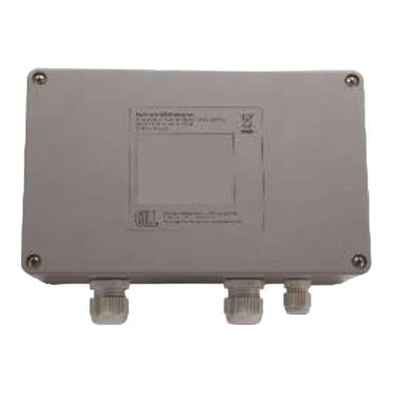
Ultrasonic Anemometer 2. IS Windobserver system contents list IS Windobserver Part: 1360-PK-106 1360-PK-052 Intrinsically safe IS WindObserver anemometer 1255-10-057 Anemometer mounting kit 1360-PK-054 Anemometer 20 Way Connector kit. 1277-30-045 Head Cover (2 halves) 1360-PK-105 Intrinsically safe Power Supply Unit (And Communications Interface). 1360-10-008 3 Metre Anemometer Test Cable. -
Page 7: Spare Part List
Power Supply Unit Box which provides the RS232 or RS422 output. The RS422 Output of the Power Supply Unit Box is designed to connect directly to the Gill WindDisplay units to provide a complete wind speed direction system. -
Page 8: Certification Overview
Ultrasonic Anemometer 5. Certification Overview 5.1. IS WindObserver Rating (1360-PK-052) • ATEX European Standard (Sira 15ATEX2014) • UKCA UK Standard (IECEx SIR 15.0013) • IECEx International Standard (CSAE 21UKEX2364) To be used in Zones 0,1 and 2 5.2. Low Voltage Power Supply Unit Rating (1360-PK-055) •... -
Page 9: Installation
Ultrasonic Anemometer 6. Installation • • • WARNING Intrinsically Safe Power Supply Unit & Communications Interface Part number: 1954-00-002 To be mounted in Non-Hazardous Area gillinstruments.com 1360-PS-0001 Issue 16 (See page 5 for applicability) - Page 10 The Intrinsically Safe WindObserver has a base mounted 20-way socket and is supplied with a mating 20-way connector requiring connection to a suitable IS cable. Intrinsically Safe Cable and Junction Boxes are not available from Gill Instruments and must be determined to be suitable for use by the customer.
-
Page 11: Installation Siting Guidelines
Ultrasonic Anemometer 6.1. Installation Siting Guidelines ➢ ➢ ➢ • • • ➢ ➢ ➢ ➢ ➢ ➢ ➢ ➢ gillinstruments.com 1360-PS-0001 Issue 16 (See page 5 for applicability) -
Page 12: Installation Guidelines
Ultrasonic Anemometer 6.2. Installation Guidelines 6.3. IS Windobserver Instructions specific to hazardous area installations (In accordance with IEC60079-0:2011 clause 30) The following instructions relevant to safe use in a hazardous area apply to equipment covered by certificate numbers IECEx SIR 15.0013, SIRA 15ATEX2014 and CSAE 21UKEX2364. The certification marking is as follows: Certificate number: IECEx SIR 15.0013... -
Page 13: Low Voltage Power Supply Unit
Ultrasonic Anemometer 6.4. Low Voltage Power Supply Unit Instructions specific to hazardous area installations in accordance with IEC60079-0:2011 clause 30. The following instructions relevant to safe use in a hazardous area apply to equipment covered by certificate numbers IECEx SIR 13.0159, Sira 13ATEX2384 and CSAE 21UKEX2363 The certification marking is as follows: Certificate number: IECEx SIR 13.0159... -
Page 14: Installation Using Low Voltage Power Supply
Ultrasonic Anemometer 6.5. Installation using low voltage power supply. The unit must be installed in accordance with the Drawing 1954-30-026. Note that the PCI box is mounted in the Safe area. Drawing 1954-30-026 issue 3, IS WindObserver System Diagram Sheet 1 of 2 gillinstruments.com 1360-PS-0001 Issue 16 (See page 5 for applicability) - Page 15 Ultrasonic Anemometer Drawing 1954-30-026 issue 3, IS WindObserver System Diagram Sheet 2 of 2. gillinstruments.com 1360-PS-0001 Issue 16 (See page 5 for applicability)
- Page 16 Ultrasonic Anemometer Drawing 1360-PK-105 issue 1 gillinstruments.com 1360-PS-0001 Issue 16 (See page 5 for applicability)
- Page 17 Ultrasonic Anemometer Drawing 5319-10-003 issue 1, DC Power Cable Diagram. gillinstruments.com 1360-PS-0001 Issue 16 (See page 5 for applicability)
- Page 18 Ultrasonic Anemometer Drawing 5319-10-003 issue 1, DC Power Cable Diagram. gillinstruments.com 1360-PS-0001 Issue 16 (See page 5 for applicability)
- Page 19 Ultrasonic Anemometer Drawing 5319-10-005 issue 1, AC/DC Power Supply Diagram. gillinstruments.com 1360-PS-0001 Issue 16 (See page 5 for applicability)
-
Page 20: Cabling
Ensure that strain relief measures are employed when installing the cables. Do not allow the whole weight of the cable to be applied to the connector. Note: Gill Instruments do not supply Intrinsically Safe cables; it is the responsibility of the customer to determine the type of cable that is suitable for each individual IS installation. - Page 21 Ultrasonic Anemometer Slot Position Grub Screw Wiring Connections between the 20-way Anemometer connector and the Power Supply Interface Box. 20 Way Mains Power Low Voltage Supply Anemometer Function Connector Supply Terminal J5 Terminal Number Pin Number Number TX+ RS422 Transmit Data to the Power Box TX- RS422 Transmit Data to the Power Box...
-
Page 22: Mounting
Ultrasonic Anemometer 6.7. Mounting Do NOT remove All the time the IS WindObserver is not in its final location, it should be protected from damage by keeping it in its original packaging, treating it as a delicate instrument. When transporting the Anemometer from its box to its install location the supplied head cover parts (1277-30-045) should be fitted around the anemometer head (see below) and secured in place using supplied Tie wraps. -
Page 23: Alignment
Ultrasonic Anemometer 6.8. Alignment The anemometer should be set to point North, see drawing 1360-G-026 as shown below, (or to some other known reference direction). This is facilitated by slots in the base for the mounting screws, which allow rotation of the anemometer for fine alignment. -
Page 24: Sealing
Ultrasonic Anemometer 6.9. Sealing The connector area at the base of the anemometer should not be directly exposed to moisture or solvents, as whilst the connectors are sealed when mated, the anemometer is vented to air at the base to avoid pressure build up. Therefore, use the gasket provided in the mounting kit. -
Page 25: Connection To A Pc Or Other Device
Ultrasonic Anemometer 7. Connection to a PC or other device Connection to a PC or other device requires the use of: 1) The specified Intrinsically Safe Power Supply Unit Interface MUST BE USED UNDER ALL CIRCUMSTANCES, CERTIFICATION AND PREVENTION OF DAMAGE TO THE ANEMOMETER DEPENDS UPON THIS. 2) Power Supply Interface to PC / Other device cable e.g., The IS Power Supply Unit supplies power to the anemometer electronics and provides conversion of the RS422 signal sent by the anemometer to a RS422 or RS232 signal for a PC. - Page 26 Ultrasonic Anemometer Connecting to a PC or External Device using the RS422 Output Maximum suggested RS422 approved twisted pair screened cable length is 1000 Metres. Intrinsically Safe PC or Device with RS422 Input Low Voltage Power Supply Box Signal Name Low Voltage PSU J4 Signal Name Terminal...
-
Page 27: Using The Anemometer With A Computer And Software
8. Using the Anemometer with a computer and software This section describes the modes and format of the data output by the anemometer. Use only the approved Gill Instruments IS Supply otherwise damage is likely to occur to the Anemometer and invalidate certification. -
Page 28: Digital Serial Output Formats
Ultrasonic Anemometer 8.1. Digital Serial Output Formats The following data modes are available from the serial output of the anemometer: - Mode 1 ASCII, UV, Continuous A,+000.00,+000.01,M,00,21 Fault free conditions. A,,,M,04,24 Fault report condition with CSV setting (O1). A,+999.99,+999.99,M,04,24 Fault report condition with Fixed Field setting (O2). Where: <STX><ID>,±UUU.UU,±VVV.VV,U,SS,<ETX>CC<CR><LF>... - Page 29 Ultrasonic Anemometer Mode 3 ASCII, UV, Polled (Point to Point only) A,+000.00,+000.01,M,00,21 Fault free conditions. A,,,M,04,24 Fault report condition with CSV setting (O1). A,+999.99,+999.99,M,04,24 Fault report condition with Fixed Field setting (O2). Where: <STX><ID>,±UUU.UU,±VVV.VV,U,SS,<ETX>CC<CR><LF> <STX> Start of string character (ASCII value 2) <ID>...
- Page 30 Ultrasonic Anemometer Mode 5 ASCII, NMEA, continuous $IIMWV,262,R,000.84,M,A*1A Fault free conditions. $IIMWV,,R,,M,V*29 Fault report condition with CSV setting (O1). $IIMWV,999,R,999.99,M,V*07 Fault report condition with Fixed Field setting (O2). Where: $IIMWV,DDD 1 ,R,MMM.MM,U,A,*cc<CR><LF> Start of string character Integrated instrument (or WI = Wind Instrument) Mean wind direction and velocity Direction in degrees Relative wind measurement...
- Page 31 Ultrasonic Anemometer Mode 7 Binary UV Short Continuous In a terminal program the Binary output will look like: - Converted it will read like:- 0x81 0x81 +000.04 -000.02 00 1 <STX>,UUU.UU, VVV.VV,SS,U<ETX><CR><LF> Where:- <STX> Start of string character (ASCII value 2) UUU.UU Wind Magnitude along U axis.
- Page 32 Ultrasonic Anemometer P Direction along U Axis (1 - +U, 0 = -U) Status Code (see Para 10.5) Units (M=m/s, N=knots, P=mph, K=kph, F=fpm) <ETX> End of string character (ASCII value 3) <CR><LF> Carriage Return and LineFeed Mode 13 ASCII Tunnel Polled (point to Point only) A,000.00,1,00,M,0F Fault free conditions.
- Page 33 Ultrasonic Anemometer Status of data (code 51 means unit still average building) <ETX> End of string character (ASCII value 3) Checksum of all Characters between <STX> and <ETX> (HEX byte) <CR><LF> Carriage Return and LineFeed (* 3 ) In Feet per Minute output mode, the string changes to MMMM.M Mode 15 ASCII Continuous Road Weather Average (RWA) With default factory RWA unit settings then upon switch on by default it will take 60 seconds before...
- Page 34 Ultrasonic Anemometer Modes 14 and 15 Road Weather Averaging Notes. The averaging is implemented with reference to the following standard: Guide to Meteorological Instruments and Methods of Observation World Meteorological Organization WMO-No8 seventh edition 2008 ISBN 978-92-63-10008-S. The direction and magnitude outputs are derived from the vector sum of U and V over the RWALONG averaging period (default 10 minutes in P1 (1Hz output)).
- Page 35 Ultrasonic Anemometer Therefore, if the RWALONG number is 10 (default) and Averaged Data Output Period is 60 seconds, then the rolling averaged Direction and Magnitude data is calculated over rolling 600 readings. Whenever the unit is powered up then until the unit has reached its minimum long term averaging interval the status code will read 51 (Measurement Average Building).
- Page 36 Ultrasonic Anemometer Mode 14 Averaging Polled (Point to Point only) Mode See Mode 15 for data output format and command explanations. For ease of use before changing to this Mode set all other WindObserver parameters first including: - Px: - Measurement Rate, (P1 to P4) this command sets the underlying measurement rate from 1Hz to 4Hz. RWASHORT xx: - Short Term Number, where xx is a number from 10 to 60.
-
Page 37: Digital Format Notes
Ultrasonic Anemometer 8.2. Digital Format Notes ASCII Polled Modes (Mode 3 UV, 4 Polar, 13 Tunnel and 14 RWA). This is available only as Point to Point (not networkable). When in the Polled mode, an output is only generated when the host system sends a Poll signal to the WindObserver consisting of the WindObserver Unit Identifier that is, the relevant letter A Z. - Page 38 Ultrasonic Anemometer G Command Averaging Using the G Command in association with modes other than M14, M15 and polled modes. The Averaging Period can be set from zero to 3600 secs. (1 hour). The default setting is zero. When averaging is enabled, data is output at a rate determined by the averaging period.
-
Page 39: Status Codes
Ultrasonic Anemometer 8.3. Status Codes transmitted in the serial string. This value will denote the system and measurement status. The codes are: Code 00 - O.K. This indicates that the system is operating correctly. The transducers signals are within the required limits and no memory faults have occurred. -
Page 40: Configuration & Software Commands
9. Configuration & Software Commands The Intrinsically Safe WindObserver can be configured using Terminal emulator software such as HyperTerminal. Alternatively, it is possible to use Gill Wind Software as a Terminal program only (Wizard and Sync Comms not from: - https://gillinstruments.com/downloads/... - Page 41 Ultrasonic Anemometer Adjust the Port settings to match WindObserver settings. WindObserver default settings are: Bits per second 9600 Data bits Parity None Stop bits Flow Control None Click on OK and data similar to the following example will scroll on screen at the output rate: The WindObserver should be outputting data as per the following screen.
- Page 42 Ultrasonic Anemometer Entering Configuration Mode From Continuous mode From Polled mode - where N is the Unit Identifier. Type * Type *N The Unit Identifier must be entered as upper-case The Intrinsically Safe WindObserver responds with a CONFIGURATION MODE message, stops reporting wind measurements, and waits for a command (as detailed below).
- Page 43 Ultrasonic Anemometer Returning to Measurement Mode Type Q and press ENTER key If in Continuous mode, the anemometer responds with wind measurements immediately, continuing at the selected Sampling rate. If in Polled mode: - Enables poll Polls anemometer (where N is the Unit identifier entered as upper-case) The anemometer replies with a single set of wind measurements &...
-
Page 44: Configuration Settings
Ultrasonic Anemometer Changing Settings To change a setting, first go into Configuration mode and then refer to the sections below. Enter the Configuration code of the new setting required, followed by press ENTER key. If successful, the new setting will be echoed back as a message by the Intrinsically Safe WindObserver. For example, to change the message format to NMEA, Type M5 and press the ENTER key. - Page 45 Ultrasonic Anemometer Dx- Diagnostic and Configuration Command Each of these commands causes a response from the Intrinsically Safe WindObserver. Command Item Typical response code Type and serial No. I03000 Software version 1.032 Current configuration: Unit configuration B3 F1 G0000 K1 L1 M2 NA O1 P1 U1 V1 X1 Anemometer power +07.9 supply voltage...
- Page 46 Ultrasonic Anemometer Mx to Mxx - Message Format Output format Configuration code ASCII UV Continuous ASCII Polar Continuous ASCII UV Polled (tri-state) ASCII Polar Polled (tri-state) NMEA Continuous Binary Tunnel Continuous Binary UV Continuous Binary Polar Continuous ASCII Tunnel Continuous ASCII Tunnel Polled (tri-state) ASCII Polar Polled Averaged ASCII Polar Continuous Averaged...
- Page 47 Ultrasonic Anemometer Q- Returning to Measurement Mode (see page 46) Road Weather Averaging Settings RWASHORT XX (Short term number) Where XX = 10 to 60, associated with Mode 14 and Mode 15 averaging. RWALONG XX (Long term number) Where XX = 1 to 10, associated with Mode 14 and Mode 15 averaging. Ux Digital Output Units knots miles / hour...
-
Page 48: Maintenance & Fault-Finding
There are no moving parts or user-serviceable parts requiring routine maintenance. Opening the unit or breaking the security seal will void the Warranty, Calibration and Certification. In the event of failure, prior to returning the unit to your authorised Gill distributor, it is recommended that: ➢... -
Page 49: Fault-Finding
Connect the IS WindObserver to a PC as detailed in Para 7 using an RS422 or RS232 connection. Open a Terminal program e.g. HyperTerminal, Tera Term or use Gill Wind Software as a Terminal program. Select the required COM port. - Page 50 Ultrasonic Anemometer To Check the Unit Settings or Change settings Type D1 and press Enter, to see serial number. Type D2 and Press Enter to see Firmware version. Type D3 to see configuration settings, e.g. SAFE MODE *************************** I000157 1.021 current configuration: B3 F1 G0000 K1 L1 M2 NA O1 P1 U1 V1 X1 Change settings if required referring to the previous configuration details.
-
Page 51: Status (Error) Codes
Gently hold the anemometer cylinder and then see if it is possible to feel the Anemometer rock on the transducers. If this occurs, then it is likely the transducer arms are misaligned requiring return to Gill Instruments for re- alignment. -
Page 52: Connections And Tests With The Low Voltage Supply Unit
Ultrasonic Anemometer 10.8. Connections and tests with the Low Voltage Supply Unit Couple the Intrinsically Safe WindObserver to the power supply unit using a known working test cable (The 3 metre test cable connections to terminal block J5 are shown following). J5 Terminal 2 IS WindObserver 3 Metre Test Cable Connection Table to LVPCI Box J5. - Page 53 Ultrasonic Anemometer Anemometer Supply Voltage and Current With the LVPCI box powered, the Supply Voltage between J5 Terminal 8 +ve and Terminal 7 (-ve) must be between 6v dc to 12v dc. Typically, 9v dc. (If the supply voltage exceeds 12 v dc damage to the Anemometer might result) The IS anemometer current through J5, Terminal 8 will typically be 14mA (maximum.
- Page 54 Ultrasonic Anemometer With the Sensor connected and outputting data to the PCI box. Check that the unit is correctly configured by going into Configuration mode and using D3, see Page 47. If a HyperTerminal connection is established to change the sensor configuration, then when a PC keystroke is undertaken then the PCI box Red Tx LED on the PCB will be seen to momentarily flash on and off.
-
Page 55: Returning Units
Ultrasonic Anemometer 10.10 Returning Units If the unit has to be returned, it should be carefully packed in the original packaging and returned to your authorised Gill distributor, with a full description of the fault condition. 11. Drawings 11.1. Low Voltage Power Supply Drawing 1954-30-023 Issue 2 Terminal Arrangement. -
Page 56: Appendix A Technical Specification For Is Windobserver
Ultrasonic Anemometer Appendix A Technical Specification for IS Windobserver Part number (1360-00-097) For use in Zone 0, 1, and 2 Wind Measurement Parameters Vectors U (South to North) and V (East to West) Polar (Speed and Direction) NMEA, Tunnel, Binary Output 1Hz (Default), 2 and 4Hz as a user configuration Averaging... - Page 57 Ultrasonic Anemometer Circuit Protection All Circuits 0.8 Joules Input/Output Parameters Please refer to the following certifications contained Sira 15ATEX2014 in appendices 2, 3, & 4 for the relevant information IECEx SIR 15.0013 CSAE 21UKEX2364 Digital Output Communication RS422, Full duplex to power and control enclosure Baud rates 1200, 2400, 4800, 9600, 19200 Formats...
-
Page 58: Appendix B Technical Specification For Low Voltage Power Supply
Ultrasonic Anemometer Appendix B Technical Specification for Low Voltage Power Supply Part number (1954-00-002) NOT For use in Zone 0, 1, and 2 Input and Outputs Digital Input RS422 Interface (Data to/from IS Windobserver connected via galvanic isolation) Digital Output RS232 and RS422 Interface (Data to/from IS Windobserver) Power Requirement Input Voltage... -
Page 59: Appendix C Technical Specification For 5319-10-005
Ultrasonic Anemometer Appendix C Technical Specification for 5319-10-005 Power Requirement Input Voltage 90 Vac to 264 Vac Output Voltage 24vdc Unit Power Consumption (No Load 75 mW Input Power) Input Power Over Voltage not present Protection Limit Input Power Reverse-Polarity Protection Limit Input Power Protection Duration Internal T1.0A/250 VAC fuse... -
Page 60: Appendix D Applicable Certificate Table
Ultrasonic Anemometer Appendix D Applicable Certificate Table Part Number Certified Component Applicable Certificates Sira 15ATEX2014 CSAE 21UKEX2364 1360-PK-052 1360-00-097 IECEx SIR 15.0013 Sira 13ATEX2384 1360-PK-055 CSAE 21UKEX2363 1954-00-002 1360-PK-105 IECEx SIR 13.0159 gillinstruments.com 1360-PS-0001 Issue 16 (See page 5 for applicability) -
Page 61: Appendix E European Approvals
Ultrasonic Anemometer Appendix E European Approvals Sira ATEX Certifications 1. Certificate Number: Sira 15ATEX2014 Issue 4 for the IS Windobserver Anemometer. (P/N 1360-00-097) 2. Certificate Number: Sira 13ATEX2384 Issue 4 for the IS Low Voltage Power Supply and Communications Unit. (P/N 1954-00-002) To check the current status and issue number of above certificates please visit the CSA Group website by following the link below. - Page 62 Ultrasonic Anemometer 1. Certificate Number: Sira 15ATEX2014 for the Windobserver IS Anemometer. (1360-00-097) gillinstruments.com 1360-PS-0001 Issue 16 (See page 5 for applicability)
- Page 63 Ultrasonic Anemometer gillinstruments.com 1360-PS-0001 Issue 16 (See page 5 for applicability)
- Page 64 Ultrasonic Anemometer gillinstruments.com 1360-PS-0001 Issue 16 (See page 5 for applicability)
- Page 65 Ultrasonic Anemometer gillinstruments.com 1360-PS-0001 Issue 16 (See page 5 for applicability)
- Page 66 Ultrasonic Anemometer 2. Certificate Number: Sira 13ATEX2384 for the IS Low Voltage Power Supply and Communications Unit. (1954-00-002) gillinstruments.com 1360-PS-0001 Issue 16 (See page 5 for applicability)
- Page 67 Ultrasonic Anemometer gillinstruments.com 1360-PS-0001 Issue 16 (See page 5 for applicability)
- Page 68 Ultrasonic Anemometer gillinstruments.com 1360-PS-0001 Issue 16 (See page 5 for applicability)
-
Page 69: Appendix F International Approvals
Ultrasonic Anemometer Appendix F International Approvals Sira IECEx Certifications 1. Certificate Number: Sira IECEx SIR 15.0013 Issue 3 for the IS Windobserver Anemometer. (P/N 1360-00-097) 2. Certificate Number: Sira IECEx SIR 13.0159 Issue 3 for the IS Low Voltage Power Supply and Communications Interface. - Page 70 Ultrasonic Anemometer 1. Certificate Number: Sira IECEx SIR 15.0013 for the IS Windobserver Anemometer (1360-00-097) gillinstruments.com 1360-PS-0001 Issue 16 (See page 5 for applicability)
- Page 71 Ultrasonic Anemometer gillinstruments.com 1360-PS-0001 Issue 16 (See page 5 for applicability)
- Page 72 Ultrasonic Anemometer gillinstruments.com 1360-PS-0001 Issue 16 (See page 5 for applicability)
- Page 73 Ultrasonic Anemometer gillinstruments.com 1360-PS-0001 Issue 16 (See page 5 for applicability)
- Page 74 Ultrasonic Anemometer 2. Certificate Number: Sira IECEx SIR 13.0159 for the IS Low Voltage Power & Communication Interface. (1954-00-002) gillinstruments.com 1360-PS-0001 Issue 16 (See page 5 for applicability)
- Page 75 Ultrasonic Anemometer gillinstruments.com 1360-PS-0001 Issue 16 (See page 5 for applicability)
- Page 76 Ultrasonic Anemometer gillinstruments.com 1360-PS-0001 Issue 16 (See page 5 for applicability)
- Page 77 Ultrasonic Anemometer gillinstruments.com 1360-PS-0001 Issue 16 (See page 5 for applicability)
- Page 78 Ultrasonic Anemometer gillinstruments.com 1360-PS-0001 Issue 16 (See page 5 for applicability)
-
Page 79: Appendix G United Kingdom & Northern Ireland Approvals
If you wish to confirm the status of the above CSAE certificates, please visit the CSA Group website below. https://www.csagroup.org/en-gb/information-centre/certificate-database/ Should you require PDF copies of the certificates please contact Gill Instruments. gillinstruments.com 1360-PS-0001 Issue 16 (See page 5 for applicability) - Page 80 Ultrasonic Anemometer 1. Certificate Number: CSAE 21UKEX2364 Issue 0 for the IS Windobserver Anemometer (1360-00-097) gillinstruments.com 1360-PS-0001 Issue 16 (See page 5 for applicability)
- Page 81 Ultrasonic Anemometer gillinstruments.com 1360-PS-0001 Issue 16 (See page 5 for applicability)
- Page 82 Ultrasonic Anemometer gillinstruments.com 1360-PS-0001 Issue 16 (See page 5 for applicability)
- Page 83 Ultrasonic Anemometer 2. Certificate Number: CSAE 21UKEX2363 Issue 0 for the IS Low Voltage Power & Communication Interface Unit (1954-00-002) gillinstruments.com 1360-PS-0001 Issue 16 (See page 5 for applicability)
- Page 84 Ultrasonic Anemometer gillinstruments.com 1360-PS-0001 Issue 16 (See page 5 for applicability)
- Page 85 Ultrasonic Anemometer gillinstruments.com 1360-PS-0001 Issue 16 (See page 5 for applicability)
- Page 86 Ultrasonic Anemometer gillinstruments.com 1360-PS-0001 Issue 16 (See page 5 for applicability)
- Page 87 We represent this supplier. For more information contact Observator Instruments: T: +31 (0)180 463411 E: info@observator.com Rietdekkerstraat 6 2984 BM Ridderkerk The Netherlands Welcome to the world of Observator oriented company with a worldwide distribution network and offices Since 1924 Observator has evolved to be a trend-setting developer in Australia, Germany, the Netherlands, and supplier in a wide variety of industries.
Need help?
Do you have a question about the IS Windobserver 1360-PK-060 and is the answer not in the manual?
Questions and answers