Table of Contents
Advertisement
Quick Links
Advertisement
Table of Contents

Related Manuals for Gill HS-50


Summary of Contents for Gill HS-50
-
Page 2: Table Of Contents
10.1.3 PCI/PCIA Operation......................18 10.1.4 PCIA Box (1189-PK-020) HS Analogue Output Connections......... 20 10.1.5 Gill Instruments HS to PCI/A Ready Made Gill Cable 1210-PK-043 ......21 SYSTEM CONNECTION DIAGRAMS ..............23 11.1 System Connection ........................23 11.2 1199-00-015 Interface Cable ....................24 USING THE ANALOGUE INPUTS WITH THE HS ELECTRONICS UNIT . - Page 3 Analogue Sync. Output ......................42 15.4 Analogue Status Output ......................42 15.5 Test Modes ..........................42 VIEWING & LOGGING THE DATA USING GILL WINDVIEW SOFTWARE ........................43 INSTRUCTIONS FOR USING WINDCONVERT BINARY TO ASCII CONVERSION UTILITY ....................49 MAINTENANCE & FAULT-FINDING ..............51 18.1...
-
Page 4: Foreword
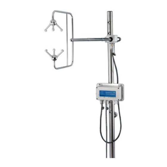
This manual describes the operation of the HS-50 (1199-PK-102) and HS-100 (1199-PK-085) The term HS is used in this manual as a general term for both the HS-50 & HS-100; they are robust three axis anemometers with no moving parts. -
Page 5: Packing List
Anemometer Power Supply & 1189-PK-020 Communications, including Analogue & Digital Outputs Power & Communications Interface – PCI, Anemometer Power Supply & 1189-PK-021 Communications, Digital Output Only Gill Instruments Anemometer Cable (RS422 & 1086-M-043/XXm Power) 20-way Hirose Connector 020-01559 ___________________________________________________________________________________________ Page 4... -
Page 6: Principle Of Operation
HS-50 & HS-100 Doc. No 1199-PS-0035 Issue 3 June 2021 5 PRINCIPLE OF OPERATION Figure 1 Time of Flight details The HS measures the times taken for an ultrasonic pulse of sound to travel from an upper transducer to the opposite lower transducer, and compares it with the time for a pulse to travel from lower to upper transducer. -
Page 7: Technical Specification
HS-50 & HS-100 Doc. No 1199-PS-0035 Issue 3 June 2021 6 TECHNICAL SPECIFICATION Parameter HS-50 HS-100 Outputs Data Output rates From 0.4 to 50Hz From 0.4 to 100Hz Measurement Rate 50Hz (Full 3 axis measurement) 100Hz (Full 3 axis measurement) -
Page 8: Installation
HS-50 & HS-100 Doc. No 1199-PS-0035 Issue 3 June 2021 7 INSTALLATION 7.1 Handling Instructions The HS frame should be stored and transported in the supplied flight case. If the frame is removed from the flight case (for instance, to carry out a bench test), the protective head cover should be left in place to protect the transducers. -
Page 9: Installation Guidelines
Satcom – 5m (avoid likely lines of sight) Use cables recommended by Gill. If cables are cut and re-connected incorrectly (perhaps in a junction box) then EMC performance may be compromised if cable screen integrity is not maintained. -
Page 10: Polar Definition
HS-50 & HS-100 Doc. No 1199-PS-0035 Issue 3 June 2021 7.4 Polar definition The wind speed in the UV plane, with direction in degrees from 0 to 359, with respect to the Reference spar (which is normally aligned to North). -
Page 11: Mechanical Installation
HS-50 & HS-100 Doc. No 1199-PS-0035 Issue 3 June 2021 Figure 3 Dimensions & Alignment Details 7.7 Mechanical installation Before installing, it is strongly recommended that a bench test is carried out. 7.8 Location Select a position so that the unit is clear of any structure, which may obstruct the airflow or induce turbulence. -
Page 12: Cabling
HS-50 & HS-100 Doc. No 1199-PS-0035 Issue 3 June 2021 7.11 Cabling Ensure that strain relief measures are employed when installing the cables. Do not allow the whole weight of a cable to be applied to the connector. An RS422 compatible cable should be used, with the number of twisted pairs matching the application. -
Page 13: Way Hirose Connector
HS-50 & HS-100 Doc. No 1199-PS-0035 Issue 3 June 2021 7.13 20 Way Hirose Connector 1 Pin Connections, rear of 20-way Hirose 2. Pin Connections, contact side of 20-way Hirose Pin Number Designation Reserved RS422 Tx+ RS422 Tx- RS422 Rx+... -
Page 14: Operation
1 and 250 (HS-100) or 2 and 250 samples (HS-50). E.g. Default Average Sett ing is 5 therefore Output Rate = 100/5 = 20Hz. -
Page 15: Wind Measurement, Sos And Temperature Reporting Format
HS-50 & HS-100 Doc. No 1199-PS-0035 Issue 3 June 2021 8.6 Wind Measurement, SoS and Temperature Reporting Format The wind measurement can be output in one of the following formats: U, V & W, calibrated (ms) U, V & W, uncalibrated (ms) Polar &... -
Page 16: Interactive Mode
HS-50 & HS-100 Doc. No 1199-PS-0035 Issue 3 June 2021 8.11 Interactive Mode Interactive mode is entered from measurement mode, by sending the anemometer the appropriate command. In this mode the user can communicate with the anemometer, issuing configuration commands to the anemometer, or requesting information from the anemometer. -
Page 17: Connection To A Pc Or Other Device
HS-50 & HS-100 Doc. No 1199-PS-0035 Issue 3 June 2021 9 CONNECTION TO A PC OR OTHER DEVICE Connection to a PC or other device requires the use of: Either a standard PCI or PCIA Or a suitable alternative power supply and RS422 conversion unit, which meets the specification of the anemometer. -
Page 18: Connecting An Hs Unit To A Pc Using Rs 422
HS-50 & HS-100 Doc. No 1199-PS-0035 Issue 3 June 2021 10 CONNECTING AN HS UNIT TO A PC USING RS 422 PC with RS422 to HS Connector RS232/USB convertor 20 way Pin Signal Names Signal Name No’s RS422 Tx+ RS422 Rx+... -
Page 19: Pci/Pcia Electrical Power Requirements
HS-50 & HS-100 Doc. No 1199-PS-0035 Issue 3 June 2021 PCI/PCIA Electrical Power Requirements 10.1.2 100Vac - 120Vac, 10VA from a mains supply for the 115V switch position. 200Vac - 250Vac, 10VA from a mains supply for the 230V switch position. - Page 20 HS-50 & HS-100 Doc. No 1199-PS-0035 Issue 3 June 2021 Assembly of Amphenol C91A Screw Lock Socket ___________________________________________________________________________________________ Page 19...
-
Page 21: Pcia Box (1189-Pk-020) Hs Analogue Output Connections
HS-50 & HS-100 Doc. No 1199-PS-0035 Issue 3 June 2021 PCIA Box (1189-PK-020) HS Analogue Output Connections. 10.1.4 If a PCIA box is available then a HS with Analogue Output option connections can be routed from the 15 Way D type Input connector directly to the Auxiliary 9 way D type Output connector. (Note: The PCIA box converts the digital output from the HS to analogue outputs). -
Page 22: Gill Instruments Hs To Pci/A Ready Made Gill Cable 1210-Pk-043
HS-50 & HS-100 Doc. No 1199-PS-0035 Issue 3 June 2021 Gill Instruments HS to PCI/A Ready Made Gill Cable 1210-PK-043 10.1.5 The optional 1086-10-043 cable allows for connection between either the PCI/PCIA and HS or the SIU. ___________________________________________________________________________________________ Page 21... - Page 23 HS-50 & HS-100 Doc. No 1199-PS-0035 Issue 3 June 2021 ___________________________________________________________________________________________ Page 22...
-
Page 24: System Connection Diagrams
HS-50 & HS-100 Doc. No 1199-PS-0035 Issue 3 June 2021 11 SYSTEM CONNECTION DIAGRAMS 11.1 System Connection ___________________________________________________________________________________________ Page 23... -
Page 25: 1199-00-015 Interface Cable
HS-50 & HS-100 Doc. No 1199-PS-0035 Issue 3 June 2021 11.2 1199-00-015 Interface Cable The 1.5 metre 1199-00-015 cable supplied allows for connection between the HS Frame and the Electronics Unit. ___________________________________________________________________________________________ Page 24... -
Page 26: Using The Analogue Inputs With The Hs Electronics Unit
HS-50 & HS-100 Doc. No 1199-PS-0035 Issue 3 June 2021 12 USING THE ANALOGUE INPUTS WITH THE HS ELECTRONICS UNIT Introduction The supplied HS Electronics Unit allows the user to integrate up to 6 analogue inputs into the HS digital string, together with a PRT input. It is designed for outdoor use please see section 12.3 for mounting details. -
Page 27: Using The Electronics Unit Prt Input
HS-50 & HS-100 Doc. No 1199-PS-0035 Issue 3 June 2021 12.2 Using the Electronics Unit PRT Input The Electronics Unit is set up to operate with any 4 wire PRT conforming to IEC 751 or DIN 43760. Compatibility with other standards may be available on request. -
Page 28: Electronics Unit Mounting Details
HS-50 & HS-100 Doc. No 1199-PS-0035 Issue 3 June 2021 12.3 Electronics Unit Mounting Details ___________________________________________________________________________________________ Page 27... -
Page 29: Configuring The Anemometer With A Pc Running Gill Wind Software
June 2021 13 CONFIGURING THE ANEMOMETER WITH A PC RUNNING GILL WIND SOFTWARE Wind is a software package from Gill Instruments that is free to download from the Gill Instruments website: http://gillinstruments.com/main/software.html It is primarily designed for use with the WindSonic and WindMaster range of anemometers but it is possible to use as a terminal package to communicate with the HS. - Page 30 June 2021 Click on the Baud rate menu and select the required Baud rate to match the HS unit. Data will start scrolling in the terminal window (assuming that the HS is configured to output in Gill ASCII mode) ___________________________________________________________________________________________...
-
Page 31: Software Commands Introduction
HS-50 & HS-100 Doc. No 1199-PS-0035 Issue 3 June 2021 To enter configuration mode, type ‘IM’, then type config and press the enter key to display the current HS configuration 13.1 Software commands Introduction Command Format All commands are entered as an ASCII string consisting of a mnemonic, representing the operation, and zero or more parameters separated by spaces and terminated by either <CR>... -
Page 32: Software Commands
HS-50 & HS-100 Doc. No 1199-PS-0035 Issue 3 June 2021 Configuration Commands On receipt of a configuration command, the anemometer will respond with a validation message if the command was successfully completed, or an appropriate error message if it was not. If a configuration command is entered with no data parameter, the current data value is returned. - Page 33 HS-50 & HS-100 Doc. No 1199-PS-0035 Issue 3 June 2021 ASCTERM Syntax: ASCTERM CR | CRLF Description: Sets ASCII output string terminator. Parameters: ASCII output string terminator is <CR>. CRLF ASCII output string terminator is <CR><LF>. AVERAGE Syntax: AVERAGE 2.to.250 (HS-50)
- Page 34 HS-50 & HS-100 Doc. No 1199-PS-0035 Issue 3 June 2021 INST Syntax: INST ON | OFF Description: When set to ON, Instantaneous Mode is enabled and no averaging is performed. When set to OFF, Instantaneous Mode is disabled and averaging is performed. In both cases the output rate is determined by the AVERAGE parameter.
-
Page 35: Using The Anemometer Digital Outputs
HS-50 & HS-100 Doc. No 1199-PS-0035 Issue 3 June 2021 14 USING THE ANEMOMETER DIGITAL OUTPUTS 14.1 Digital Serial Output Format Data is sent in either binary or ASCII format as follows: Binary Result Message Format (post conversion) 14.1.1 00.1 00.0... -
Page 36: Ascii Result Message Format
HS-50 & HS-100 Doc. No 1199-PS-0035 Issue 3 June 2021 ASCII Result Message Format 14.1.2 0.06 0.03 350.4 99.99 0.0001 0.0001 0.0001 0.0001 0.0001 0.0001 StaA StaD term where: <STX> - Start of string character (ASCII value 2) StaA Status Address... -
Page 37: Status Fields
HS-50 & HS-100 Doc. No 1199-PS-0035 Issue 3 June 2021 14.2 Status Fields There are a number of different status codes, which give the user information about various aspects of the anemometer. Each of these codes has an address field followed by a data field. The address field defines which particular aspect of the anemometer the following data field refers to. - Page 38 HS-50 & HS-100 Doc. No 1199-PS-0035 Issue 3 June 2021 StaD - Status Data Address 00 - Error codes Function Transducer pair 1 failed. Transducer pair 2 failed Transducer pair 3 failed Reserved Non-volatile memory error PRT failed Reserved Reserved...
- Page 39 HS-50 & HS-100 Doc. No 1199-PS-0035 Issue 3 June 2021 Bits 5,4 Reserved Reserved Reserved Reserved Bits 7,6 Reserved Reserved Reserved Reserved Address 04 - Error code history Function Reserved Reserved Reserved Reserved Non-volatile memory error PRT failed Reserved Reserved The error history is cleared when the user enters interactive mode.
-
Page 40: Inclinometer Readings
HS-50 & HS-100 Doc. No 1199-PS-0035 Issue 3 June 2021 14.2.1 Inclinometer Readings The following data string information is taken from an Anemometer, the Inclinometer data readings are in bold. U’ V’ W’ ST(C) Sa Sb 04,20,+06.16,+02.25,-01.78,+025.82 05,00,+06.19,+02.03,-01.86,+025.79 06,01,+06.17,+01.79,-01.88,+025.82 07,03,+06.23,+01.59,-01.78,+025.85 08,01,+06.22,+01.55,-01.88,+025.86... - Page 41 HS-50 & HS-100 Doc. No 1199-PS-0035 Issue 3 June 2021 Positive and negative x values are the tilt angles of Research Unit as illustrated in the diagrams below. Similarly, the positive and negative y values are as illustrated below. U’: U axis velocity in 0.01 m/s unit.
-
Page 42: Using Analogue Outputs With Pcia Box
HS-50 & HS-100 Doc. No 1199-PS-0035 Issue 3 June 2021 15 USING ANALOGUE OUTPUTS WITH PCIA BOX (1189-PK-020). 15.1 Introduction Analogue outputs can be provided by using the optional PCIA. The analogue output card decodes the serial message from the anemometer and generates the appropriate analogue outputs. Seven analogue outputs are provided of 14 bit resolution. -
Page 43: Analogue Sync. Output
HS-50 & HS-100 Doc. No 1199-PS-0035 Issue 3 June 2021 15.3 Analogue Sync. Output A logic 1 on the Sync/Auxiliary output (pins 6 & 7 of the 9-way D type connector on the PCI/A) indicates that the analogue outputs have settled. A logic 0 is generated during the period when the analogue outputs are being updated (approximately 2ms duration). -
Page 44: Viewing & Logging The Data Using Gill Windview Software
June 2021 16 VIEWING & LOGGING THE DATA USING GILL WINDVIEW SOFTWARE WindView is a software package from Gill Instruments that is free to download from the Gill Instruments website: http://gillinstruments.com/main/software.html It is designed to allow the user to view and log data from a single or multiple anemometers. - Page 45 June 2021 Select Connect from the File Drop down menu. The Output Format field should match the sensor ie Gill Polar, 3 axis UV or NMEA. Select the required COM Port from the menu. Select the required baud rate to match the sensor eg 9600 baud.
- Page 46 HS-50 & HS-100 Doc. No 1199-PS-0035 Issue 3 June 2021 Data should scroll on screen. To Log data use Settings menu and select logging. ___________________________________________________________________________________________ Page 45...
- Page 47 HS-50 & HS-100 Doc. No 1199-PS-0035 Issue 3 June 2021 Select type of log, in this case continuous with boxes ticked for append time stamp and append record count if required. Select a file directory and file name. Click on Apply.
- Page 48 HS-50 & HS-100 Doc. No 1199-PS-0035 Issue 3 June 2021 To Start the Logging Select File/Log/Start. To Stop the Logging Select File/Log/Stop. ___________________________________________________________________________________________ Page 47...
- Page 49 HS-50 & HS-100 Doc. No 1199-PS-0035 Issue 3 June 2021 Example HS data logged Notepad. ___________________________________________________________________________________________ Page 48...
-
Page 50: Instructions For Using Windconvert Binary To Ascii Conversion Utility
17 INSTRUCTIONS FOR USING WINDCONVERT BINARY TO ASCII CONVERSION UTILITY WinConvert can be used with the Research & WindMaster range of Gill Anemometers to convert logged Binary data into a readable ASCII format. It is available to download from the Gill Instruments website: http://gillinstruments.com/main/software.html... - Page 51 HS-50 & HS-100 Doc. No 1199-PS-0035 Issue 3 June 2021 Select the type of anemometer the binary file was generated by (or leave unknown selected if the anemometer type is unknown), click begin to start the process and the following window will...
-
Page 52: Maintenance & Fault-Finding
There are no moving parts or user-serviceable parts requiring routine maintenance. Opening the unit or breaking the security seal will void the warranty and the calibration. In the event of failure, prior to returning the unit to your authorised Gill distributor, it is recommended that: 1. -
Page 53: Head Alignment Test
HS. These values should be within ±3°C of each other within the temperature range specified above. If the Sonic Temperature reports outside of this tolerance range, the HS has potentially suffered head distortion. If this is the case the HS will need to be returned to Gill Instruments for investigation. -
Page 54: Summary Of Abbreviations Used In This Manual
HS-50 & HS-100 Doc. No 1199-PS-0035 Issue 3 June 2021 20 APPENDIX A Summary Of Abbreviations Used In This Manual ASCII American Standard Code for Information Interchange PCIA Power & Communications Interface with Analogue Outputs Power & Communications Interface Sensor Input Unit...
Need help?
Do you have a question about the HS-50 and is the answer not in the manual?
Questions and answers