
Related Manuals for PVR DRY CR 60


Summary of Contents for PVR DRY CR 60
- Page 1 DRY CR 60 DRY CR 150 DRY CR 400 DRY CR 500 DRY CR 1000 Claw vacuum pumps Operating and maintenance instructions Publication Number: LI 4947.P0 November 2020 TRANSLATION...
-
Page 2: Table Of Contents
Operating and maintenance instructions Index 1. General information ....................page 3 2. Installation ......................page 4 2.1 Pump description ..................... page 4 2.2 Unpacking ......................page 4 2.3 Location ......................page 4 2.4 Power Requirements ..................page 5 2.5 Vacuum Connections ..................page 6 2.6 Oil Filling on Gear Box ..................page 7 3. -
Page 3: General Information
Operating and maintenance instructions 1. General information This manual contains information necessary for the proper operation of the pump in order to prevent unsuitable use and for the safety of the operators. Do not attempt any other type of operation without having first contacted our Service Department. The information provided herewith does not intend to replace, integrate or change any rules, regulations, law by decree, directive or law of specific character in force in the Country where the installation takes place. -
Page 4: Installation
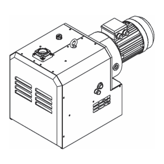
Operating and maintenance instructions 2. Installation 2.1 Pump description The DRY CR compressor is dry and contactless machines, enclosed in acoustic sound shied and designed to have cooling air passed through the sound shied by fan. The warm air is exhausted through the vent. The DRY CR is constructed in modular construction consisting of two compartments: pumping and gear chambers separated by using labyrinth seals. -
Page 5: Power Requirements
Operating and maintenance instructions 2.4 Power Requirements A schematic diagram for the electrical motor terminal connections is located in the junction box of the motor or on the motor nameplate. Typical wirings for Three Phase Motors are as below: WIRING SCHEME- THREE PHASE MOTOR 230 V 400 V The motor must be connected according to the electrical codes through a fused switch... -
Page 6: Vacuum Connections
Consult P.V.R. for recommendations. The following thread sizes are standard on the pumps (NPT thread is available upon request) Pump Model Inlet Size Exhaust Size DRY CR 60 G 1” G 1” DRY CR 150 G 1-1/2” G 1-1/2”... -
Page 7: Oil Filling On Gear Box
Operating and maintenance instructions 2.6 Oil Filling on Gear Box The pump is shipped without oil in gear box. After level installation and correct rota- tion has been established, fill the pump with recommended gear oil through the oil fill port. -
Page 8: Safety
Operating and maintenance instructions 3. Safety Please read the following safety notices carefully before operating the pump. 3.1 General Notices • Understand fully this installation and operating manual before operation. • The other person except authorized operator should not operate the vacuum pump. •... -
Page 9: Operation
Operating and maintenance instructions 4. Operation 4.1 Start-up Check rotation of the motor as described in Section 2.4 (Power Requirements). Fill the pump with oil as described in Section 2.6 (Oil Filling). Start the pump with the inlet closed. Run the pump for a few minutes and then shut down. -
Page 10: Maintenance
Operating and maintenance instructions CAUTION: Failure to ensure proper operating conditions may lead to severe injury to persons and damage to the pump. CAUTION: Maximum number of motor starts per hour should not exceed 10 per hour. Excessive starting of the motor can cause overheating and premature failure of the motor. -
Page 11: Inline (Inlet) Filter
Operating and maintenance instructions Pump Model Oil Model Capacity (liter) Ambient temperature [°C] DRY CR 60 O.60 DRY CR 150 0.40 Rotant VF 805 DRY CR 400 1.80 5-30°C DRY CR 500 1.80 DRY CR 1000 2.80 Do not add fill oil with pump running! Do not overfill. -
Page 12: Maintenance Chart
Operating and maintenance instructions 5.3 Maintenance Chart Check inline inlet filter element/mesh. (this might need to be performed Weekly more often if there are high particulates in the inlet stream) Monthly Check the oil level and protective mesh. Check fans and coupling. Inspection hole with G1”... - Page 13 Operating and maintenance instructions Problem Probable Cause Remedy Blocked inlet mesh Check and clean mesh as necessary. Replace damaged mesh. Do not run the machine without the inlet mesh in place, as even small solids entering the pumping chamber can cause the unit to fail. Insufficient Leaks in the vacuum Check process piping for leaks.
-
Page 14: Commissioning
Operating and maintenance instructions Problem Probable Cause Remedy Ambient temperature too Provide adequate ventilation for the installation area so high that the ambient temperature never is above 40°C (104°F). Operating Temperature too High Dirty or Blocked Mesh (See blocked inlet mesh above) Vacuum regulator set over Set the point again or replace it with new one. -
Page 15: Disposal
Operating and maintenance instructions 9. Disposal Meaning of the “WEEE” logo found in labels The following symbol is applied in accordance with the EC WEEE (Waste Electrical and Electronic Equipment) Directive. This symbol (valid only in countries of the European Community) indicates that the product it applies to must NOT be disposed of together with ordinary domestic or industrial waste but must be sent to a differentiated waste collection system. - Page 16 HEADQUARTERS: Via Santa Vecchia, 107 - 23868 Valmadrera (LC), Italy T +39 0341 1918 51 - F +39 0341 1918 599 info@pvr.it - www.pvr.it LOCAL UNIT: Via IV Novembre, 104F 23868 Valmadrera (LC), Italy...
Need help?
Do you have a question about the DRY CR 60 and is the answer not in the manual?
Questions and answers