Table of Contents
Advertisement
Quick Links
PZ62E
E-500/E-501 Series
Modular Piezo Amplifier / Controller
User Manual
Version: 2.16.0
Physik Instrumente (PI) GmbH & Co. KG, Auf der Römerstraße 1, 76228 Karlsruhe, Germany
Phone +49 721 4846-0, fax +49 721 4846-1019, e-mail info@pi.ws, www.pi.ws
Date: 4/26/2024
This document describes the following products:
E-500 and E-501
Housing with power supply
E-503, E-504, E-505, E-506, E-508
Amplifier modules
E-509
Sensor / servo controller modules
E-515
Display module
E-518
Interface module
Advertisement
Table of Contents

Related Manuals for Physik Instrumente E-500 Series


Summary of Contents for Physik Instrumente E-500 Series
- Page 1 E-509 Sensor / servo controller modules E-515 Display module E-518 Interface module Physik Instrumente (PI) GmbH & Co. KG, Auf der Römerstraße 1, 76228 Karlsruhe, Germany Phone +49 721 4846-0, fax +49 721 4846-1019, e-mail info@pi.ws, www.pi.ws...
- Page 2 (https://www.physikinstrumente.com/download/TPSWNote_PhysikInstrumenteGmbH_Co_KG.pdf) on our website. © 2024 Physik Instrumente (PI) GmbH & Co. KG, Karlsruhe, Germany. The text, images, and drawings in this manual are protected by copyright. Physik Instrumente (PI) GmbH & Co. KG reserves all rights in this respect.
-
Page 3: Table Of Contents
Contents About this Document Objective and Target Audience of this User Manual ..........1 Symbols and Typographic Conventions..............1 Figures ........................2 Other Applicable Documents ..................2 Downloading Manuals ....................2 Safety Intended Use ......................3 General Safety Instructions ..................3 Safety Measures for Installation, Startup and Operation .......... - Page 4 Component Description E-500.00 19-Inch Housing with Internal Power Supply ..........19 7.1.1 Specifications ....................19 7.1.2 Dimensions ....................19 E-501.00 9.5-Inch Housing with Internal Power Supply ........... 20 7.2.1 Specifications ....................20 7.2.2 Dimensions ....................20 E-503 3-Channel Piezo Amplifier ................20 7.3.1 Front Panel Elements ...................
- Page 5 7.10 E-518 Interface Module .................... 52 7.10.1 Front Panel Elements ................... 52 7.10.2 Specifications ....................54 7.10.3 Pin Assignment .................... 54 7.11 Dummy Modules ...................... 55 7.11.1 Overview ...................... 55 7.11.2 Front Panel Elements of E-596 Modules ............. 56 Integrating Modules in Third-Party Systems Safety Measures for Integration in Third-Party Systems .........
-
Page 7: About This Document
1 About this Document About this Document Objective and Target Audience of this User Manual This user manual contains the information required for using the E-500 / E-501 series piezo control electronics (referred to as “E-500 / E-501 system” in this manual) as intended. It assumes that the reader has a fundamental understanding of basic servo systems as well as motion control concepts and applicable safety procedures. -
Page 8: Figures
1 About this Document Figures For better understandability, the colors, proportions, and degree of detail in illustrations can deviate from the actual circumstances. Photographic illustrations may also differ and must not be seen as guaranteed properties. Other Applicable Documents Some of the devices mentioned in this documentation are described in detail in separate manuals or technical notes. -
Page 9: Safety
2 Safety Safety Intended Use E-500 / E-501 system is a laboratory device according to DIN EN 61010. It is intended to be used in interior spaces and in an environment which is free from dirt, oil, and lubricants. According to its design, the E-500 / E-501 system is intended for driving capacitive loads (e.g., piezo ceramic actuators). -
Page 10: Safety Measures For Installation, Startup And Operation
2 Safety Safety Measures for Installation, Startup and Operation Improper installation of the E-500 / E-501 system can result in personal injury and/or damage to the E-500 / E-501 system. Install the E-500 / E-501 system near the power supply so that the power plug can be quickly and easily disconnected from the mains. -
Page 11: Organizational Measures
2 Safety Organizational Measures User manual Always keep this user manual with the E-500 / E-501 system. The latest versions of the user manuals are available for download on our website (p. 2). Add all manufacturer information such as supplements or technical notes to the user manual. -
Page 13: Product Description
3 Product Description Product Description Component Overview Figure 1: Example of a three-channel system: E-501 housing with E-509 sensor / servo controller module, E-503 piezo amplifier module and E-518 interface module 3.1.1 Housings The E-500 and E-501 housings are based on an EMI-proven housing with multi-function power supply and a backplane carrying all connectors to the system amplifiers, servo controllers and interface modules. -
Page 14: Amplifier Modules
3 Product Description 3.1.2 Amplifier Modules Product no. Description E-503.00 Piezo amplifier module, -30 to 130 V, three channels E-503.00S Piezo amplifier module, -30 to 130 V, one of three channels is fixed (100 V) E-504.00F High-power piezo amplifier module, 1 channel, 280 W peak power, 100 W average power, -30 to 130 V E-505.00 Piezo amplifier module, 2 A, -30 to 130 V, 1 channel... -
Page 15: Configuration Example
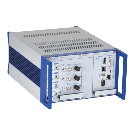
3 Product Description Configuration Example Figure 2: Configuration example of a modular three-channel controller The figure above shows a three-channel configuration example consisting of the following components: 1 × E-500.00 housing with power supply 3 × E-505.00 piezo amplifier module, 1 channel (amplifier channels 1, 2, and 3) ... -
Page 16: Signal Path Diagram
3 Product Description Signal Path Diagram Figure 3: Interconnections between E-518 interface module, amplifier module and E-509 sensor / servo controller module INFORMATION The backplane of the housing (E-500.00 or E-501.00) carries all connectors to the modules of the system (amplifiers, sensor / servo controller modules, interface /display modules). Version: 2.16.0 PZ62E E-500 / E-501 System... -
Page 17: Servo Modes
3 Product Description Servo Modes E-500 / E-501 systems support the following servo modes: Open-loop operation Closed-loop operation (only if an E-509 sensor / servo controller module is included) In closed-loop operation, the control input is interpreted as target position. The servo-control circuit is active and compares the sensor signal with the target position. -
Page 19: Unpacking
4 Unpacking Unpacking 1. Unpack the E-500 / E-501 system with care. 2. Compare the contents with the scope of delivery according to the contract and the delivery note. 3. Inspect the contents for signs of damage. If any parts are damaged or missing, contact our customer service department immediately (p. -
Page 21: Installing
5 Installing Installing Power Connection The power connection is located on the rear panel of the housing. Unless requested otherwise, the E-500 / E-501 system will be set up for the line voltage we believe predominant in your country. How to adapt E-500 / E-501 system to a different line voltage: If your system uses a 19-inch housing (E-500.00), it is equipped with a wide-range ... -
Page 22: Connecting Cables
5 Installing Connecting Cables INFORMATION Each E-509 sensor / servo controller module is calibrated with one particular piezo actuator. That piezo actuator must always be connected to the same controller channel. Labels on the rear panel of the E-500 / E-501 system indicate the serial numbers of the piezo actuators that belong to each channel. -
Page 23: Startup
6 Startup Startup Starting Analog Operation 1. Turn all DC-OFFSET potentiometers CCW (zero offset). 2. Turn all SERVO switches to OFF (open-loop operation). 3. Turn the power on. The standard screen appears on the display. The current output voltages and displacements derived from the sensor signals are displayed for all channels. -
Page 25: Component Description
7 Component Description Component Description E-500.00 19-Inch Housing with Internal Power Supply 7.1.1 Specifications Model E-500.00 Function 19-inch housing for piezo controller system: Amplifier modules, sensor / servo controller modules, interface / display modules Channels 1, 2, 3 (max. three amplifier modules) Dimensions 450 mm ×... -
Page 26: E-501.00 9.5-Inch Housing With Internal Power Supply
7 Component Description E-501.00 9.5-Inch Housing with Internal Power Supply 7.2.1 Specifications Model E-501.00 Function 9.5-inch housing for piezo controller system: Amplifier modules, sensor / servo control modules, interface / display modules Channels 1, 3 (max. one amplifier module) Dimensions 236 mm ×... -
Page 27: Front Panel Elements
7 Component Description 7.3.1 Front Panel Elements Figure 6: E-503.00 amplifier module Figure 7: E-503.00S amplifier module Labeling Type Function POWER Amplifier state: Green/off Green: E-503 is ready for normal operation. Off: The E-500 / E-501 system is switched off. ... -
Page 28: Operating Limits
7 Component Description 7.3.2 Operating Limits Figure 8: E-503 operating limits with various piezo loads (open-loop), capacitance is measured in µF 7.3.3 Specifications E-503.00 / E-503.00S Function Power amplifier Channels 3 / 2 Amplifier Input voltage range -2 to +12 V Output voltage -30 to 130 V (E-503.00S: Additional fixed voltage of 100 V) -
Page 29: Pin Assignment
7 Component Description E-503.00 / E-503.00S Interfaces and operation Piezo connection (voltage socket) LEMO ERA.00.250.CTL Analog input / control input socket DC offset setting 10-turn potentiometer, adds 0 to 10 V to the input voltage Miscellaneous Operating temperature range 5 to 50 °C Overheat protection Deactivation at 85 °C Dimensions... -
Page 30: E-504 High-Power Piezo Amplifier, Energy Recovery
7 Component Description E-504 High-Power Piezo Amplifier, Energy Recovery DANGER Risk of electric shock! The E-504 amplifier can output up to 130 V. Touching this high voltage can result in serious injury or death from electric shock. Operate a piezo actuator on the “PZT” socket only when it is connected to a protective earth conductor. -
Page 31: Operating Limits
7 Component Description Labeling Type Function CONTROL INPUT In analog operation, this control input voltage specifies the target (either as voltage or position, -2 to +12 V depending on the servo mode). The input signal should always be in the range of 0 to 10 V (excursions to -2 or +12 V may cause overflow, especially in closed-loop operation, and reduce actuator lifetime). -
Page 32: Specifications
7 Component Description 7.4.3 Specifications E-504.00F Function Power amplifier with energy recovery Channels Amplifier Input voltage range -2 to 12 V Output voltage -30 to 130 V Peak output power (<5 ms) 280 W Average output power 100 W at full voltage range Peak current (<5 ms) 2000 mA Average output current... -
Page 33: Pin Assignment
7 Component Description Examples: The small-signal capacitance of the connected piezo actuator is 550 nF, hence its large-signal capacitance is approx. 1.1 μF (2 * 550 nF). Under large-signal conditions, approx. 58 W will be allocated to the internal base load (1.5 μF), while approx. 42 W will be available for the external piezo load. -
Page 34: Front Panel Elements
7 Component Description 7.5.1 Front Panel Elements Figure 11: E-505.00 and E-505.10 amplifier Figure 12: E-505.00S amplifier module modules Labeling Type Function POWER Amplifier state: Green/off Green: E-505 is ready for normal operation. Off: The E-500 / E-501 system is switched off. ... -
Page 35: Operating Limits
7 Component Description 7.5.2 Operating Limits Figure 13: E-505 operating limits with various piezo loads (open-loop), capacitance is measured in µF 7.5.3 Specifications E-505.00 E-505.10 E-505.00S Function Power amplifier Power amplifier for Offset voltage source switching for tip/tilt systems applications* Channels Amplifier Input voltage range... -
Page 36: Pin Assignment
7 Component Description E-505.00 E-505.10 E-505.00S Interfaces and operation Piezo connection socket LEMO ERA.00.250.CTL LEMO ERA.00.250.CTL LEMO ERA.00.250.CTL Analog input DC offset setting 10-turn 10-turn potentiometer, adds potentiometer, adds 0 to 10 V to the input 0 to 10 V to the input voltage voltage Miscellaneous... -
Page 37: E-506 Linearized Piezo Amplifier, Charge Control
7 Component Description E-506 Linearized Piezo Amplifier, Charge Control DANGER Risk of electric shock! The E-506 amplifier can output up to 130 V. Touching this high voltage can result in serious injury or death from electric shock. Operate a piezo actuator on the “PZT” socket only when it is connected to a protective earth conductor. - Page 38 7 Component Description Labeling Type Function POWER Amplifier state: Green/off Green: E-506 is ready for normal operation. Off: The E-500 / E-501 system is switched off. OVERTEMP Overtemp state: Red/off Red: Piezo voltage output is deactivated due to ...
-
Page 39: Operating Limits
7 Component Description 7.6.2 Operating Limits Figure 15: E-506 operating limits with various piezo loads (open-loop), capacitance is measured in µF. The minimum capacitive load is 0.3 µF. 7.6.3 Specifications E-506.10 Function Linearized amplifier module, charge controlled Channels Amplifier Input voltage range -2 to 12 V Output voltage* -30 to 130 V... -
Page 40: Pin Assignment
7 Component Description Interfaces and operation Piezo connection (voltage socket) LEMO 2-pin EGG.0B.302.CLL Analog input / control input socket DC offset setting 10-turn potentiometer, adds 0 to 10 V to the input voltage Piezo temperature sensor (input) PT 1000; LEMO socket; automatic deactivation of high voltage output at max. - Page 41 7 Component Description PT1000 Temperature sensor Figure 17: LEMO EPL.OS.303.HLN temperature Figure 18: Schematic circuit diagram of sensor socket temperature sensor Pin 1: Temp_SA Pin 2: Temp_S Pin 3: GND/PE Housing: Protective earth conductor/GND/PE 32-pin connector, DIN 41612, male PIN a PIN c Power Fail OUT: ch1 (BNC+Offset)
-
Page 42: E-508 High-Power Piezo Amplifier With 1100 V Output Voltage
7 Component Description E-508 High-Power Piezo Amplifier with 1100 V Output Voltage DANGER Risk of electric shock! The E-508 amplifier can output up to 1100 V. Touching this high voltage can result in serious injury or death from electric shock. ... -
Page 43: Operating Limits
7 Component Description Labeling Type Function CONTROL INPUT E-508.00: BNC In analog operation, this control input voltage specifies the target (either as voltage or position, E-508.OE: SMB depending on the servo mode). Input voltage range: Open-loop operation: ±1/100 of selected ... -
Page 44: Specifications
7 Component Description 7.7.3 Specifications E-508.00 E-508.OE Function Power amplifier for PICA high- Power amplifier for PICA high- voltage piezo actuators voltage piezo actuators Amplifier Output voltage 3 to +1100 V (default) 3 to 1100 V (default) Adjustable: Optional: -260 to +780 V -260 to +780 V -550 to +550 V -550 to +550 V... -
Page 45: Pin Assignment
7 Component Description Bipolar actuators Here the output voltage swing is so chosen that the actuator sees both negative and positive high voltages. The output always has one lead at 0 V, and here the other is in a zero-crossing range, commonly·±500·V. -
Page 46: E-508.00 Gain Polarity And Output Range Settings
7 Component Description 7.7.6 E-508.00 Gain Polarity and Output Range Settings NOTICE Electrostatic hazard! The E-500 / E-501 system contains electrostatic-sensitive devices (ESD) and can be damaged if handled improperly. Avoid touching components, pins, and PCB traces. Before touching an electronic component, discharge yourself of any electric charges: −... -
Page 47: E-509 Sensor / Servo Controller Module
7 Component Description Setting the Gain Polarity Switch It is important to understand the relation between gain and the control input range. With DC-OFFSET = 0 (full CCW), the control input range is equal to output range (as set below) divided by the gain. -
Page 48: Front Panel Elements Of Modules For Capacitive Sensors
7 Component Description 7.8.1 Front Panel Elements of Modules for Capacitive Sensors Figure 23: Figure 24: Figure 25: E-509.C1A sensor / servo E-509.C2A sensor / servo E-509.C3A sensor / servo controller module controller module controller module Labeling Type Function LEMO Input for the Target sensor signal from the piezo stage. -
Page 49: Front Panel Elements Of Modules For Strain Gauge Sensors
7 Component Description 7.8.2 Front Panel Elements of Modules for Strain Gauge Sensors Figure 26: Figure 27: E-509.S1 sensor / servo controller module E-509.S3 sensor / servo controller module INFORMATION In the labeling of E-509.S1 and E-509.S3 modules, X stands for S. Labeling Type Function... -
Page 50: Specifications
7 Component Description Labeling Type Function SENSOR MONITOR E-509.S1: Output of the monitor signal(s) for the sensor channel(s). Pin assignment for E-509.S3 on p. 45. E-509.S3: LEMO ERA.0S.303.CLL 7.8.3 Specifications E-509.C1A / E-509.C2A / E-509.S1 / E-509.S3 E-509.C3A Function Sensor evaluation and position Sensor evaluation and position servo control electronics for servo control electronics for... -
Page 51: Pin Assignment
7 Component Description 7.8.4 Pin Assignment SENSOR socket of E-509.S3 and E-509.S1 Figure 28: Strain gauge sensor wiring for various piezo actuators E-500 / E-501 System PZ62E Version: 2.16.0... - Page 52 7 Component Description SENSOR MONITOR socket of E-509.S3 Figure 29: LEMO ERA.0S.303.CLL sensor monitor socket, 3-pole The SENSOR MONITOR socket carries the signals from all three channels. Each E-509.S3 comes with the E-808.90 sensor-monitor cable. The purpose of this cable is simply to split up the signals of the SENSOR MONITOR socket for the three channels.
- Page 53 7 Component Description Each capacitive sensor version comes with the D-893.32 sensor monitor cable (2 m). The purpose of this cable is simply to split up the signals of the SENSOR MONITOR socket onto three separate BNC connectors. The BNC connectors are each labeled with the channel number. E-509.S3 32-pin connector, DIN 41612, male Function Function...
- Page 54 7 Component Description E-509.C1A, E-509.C2A, E-509.C3A 32-pin connector, DIN 41612, male Function on Function on .C3A .C2A .C1A .C3A .C2A .C1A n.c. Control signal output CH1 + 15 V + 15 V - 15 V - 15 V n.c. n.c. internal use Control signal n.c.
-
Page 55: E-515 Display Modules
7 Component Description E-515 Display Modules 7.9.1 Front Panel Elements Figure 31: E-515.03 display module Figure 32: E-515.01 display module INFORMATION In the labeling of E-515.01 and E-515.03 display modules, X stands for the number of channels. Labeling Type Function MICRONS / Toggle Switch for selection of the signal to be displayed for the channel:... -
Page 56: Pin Assignment
7 Component Description 7.9.3 Pin Assignment E-515.01 and E-515.03 32-pin connector, DIN 41612, male Figure 33: Pin assignment for E-515.01 and E-515.03 Version: 2.16.0 PZ62E E-500 / E-501 System... -
Page 57: Display Adjustment
7 Component Description 7.9.4 Display Adjustment NOTICE Electrostatic hazard! The E-500 / E-501 system contains electrostatic-sensitive devices (ESD) and can be damaged if handled improperly. Avoid touching components, pins, and PCB traces. Before touching an electronic component, discharge yourself of any electric charges: −... -
Page 58: E-518 Interface Module
7 Component Description Making the display adjustment elements accessible Only remove modules from the housing when you are authorized and have the corresponding qualifications. 1. Disconnect the E-500 / E-501 system from the mains by pulling the power plug. 2. Wait a minute to be sure that any residual voltage has dissipated. 3. - Page 59 7 Component Description Labeling / Type Function appearance RS-232 D-sub 9 panel plug Serial connection to PC. (p. 54) Default baud rate: 115200 Refer to “Establishing Communication via the RS-232 Interface” in the E-518 user manual (E518T0001) for details. Left LED Shows the status of the GCS parser: Green/red/off Continuously green: E-518 is ready for normal...
-
Page 60: Specifications
7 Component Description 7.10.2 Specifications E-518.I3 Function Digital interface module for the E-500 system (E-500, E-470, E-481, E-482) Channels Supported functions Wave generator. Data recorder. Macro programming. Processor DSP 376 MHz Sampling rate, sensor 200 kHz Servo control rate 25 kHz Sensor resolution ADC: 20 bits, oversampling + filter Voltage resolution... -
Page 61: Dummy Modules
7 Component Description Digital inputs 1 to 3 (pins 13, 12, 11): TTL, 3.3 V, 5 V compatible Reset input (pin 2): Internal pull-up to 3.3 V low (0 V) = reset (same behavior as with the RBT command) high (3.3 V) = on (default) ... -
Page 62: Front Panel Elements Of E-596 Modules
7 Component Description INFORMATION Do not operate your E-500 / E-501 system when the dummy modules are removed. Without these modules, the system will malfunction because no control signal can be fed into the amplifier module due to the broken circuit. 7.11.2 Front Panel Elements of E-596 Modules Figure 38:... -
Page 63: Integrating Modules In Third-Party Systems
8 Integrating Modules in Third-Party Systems Integrating Modules in Third-Party Systems Safety Measures for Integration in Third-Party Systems DANGER Risk of electric shock! The amplifier modules of the E-500 / E-501 series output up to 130 V (E-503, E-504, E-505, E-506) or up to 1100 V (E-508). -
Page 64: Supply Power For The Modules
8 Integrating Modules in Third-Party Systems Supply Power for the Modules The supply power must be stable within a range of 2 % of the nominal value. For stable supply power with dynamic operation of high piezo loads, the power supply must be equipped with a sufficiently dimensioned buffer capacitor. -
Page 65: Maintenance
9 Maintenance Maintenance Cleaning the E-500 / E-501 system NOTICE Short circuits or flashovers! The E-500 / E-501 system contains electrostatic-sensitive devices that can be damaged by short circuits or flashovers when cleaning fluids get into the housing. Before cleaning, disconnect the E-500 / E-501 system from the mains by pulling the power plug. - Page 66 9 Maintenance Tools and accessories Slot screwdriver Two suitable fuses: Model Line voltage ranges and fuse values E-500.00 100 to 240 V AC 2 × IEC T2AH, 250 V E-501.00 100 to 120 V AC 220 to 240 V AC 2 ×...
-
Page 67: Customer Service Department
10 Customer Service Department Customer Service Department For inquiries and orders, contact your PI sales engineer or send us an email (service@pi.de). If you have questions concerning your system, provide the following information: Product and serial numbers of all products in the system −... -
Page 69: Technical Data
11 Technical Data Technical Data 11.1 Maximum Ratings The E-500 / E-501 system is designed for the following operating data: Model Maximum operating Operating frequency Maximum power voltage consumption System in E-500.00 100 to 240 V AC 50-60 Hz 180 W housing (fuses: 2 ×... -
Page 71: Old Equipment Disposal
Dispose of your old equipment according to international, national, and local rules and regulations. To fulfill the responsibility as the product manufacturer, Physik Instrumente (PI) GmbH & Co. KG undertakes environmentally correct disposal of all old PI equipment made available on the market after 13 August 2005 without charge. -
Page 73: European Declarations Of Conformity
13 European Declarations of Conformity European Declarations of Conformity For the E-500 / E-501 modular piezo amplifier controller, declarations of conformity were issued according to the following European statutory requirements: Low Voltage Directive EMC Directive RoHS Directive The standards applied for certifying conformity are listed below. Safety (Low Voltage Directive): EN 61010-1 EMC: EN 61326-1 RoHS: EN IEC 63000... -
Page 75: Appendix
14 Appendix Appendix 14.1 Lifetime of PICMA® Actuators The lifetime of a PICMA® piezo actuator can be influenced by the following factors: Applied voltage Temperature Relative humidity The following diagrams show how the individual factors influence the lifetime of the actuator. Figure 40: Dependency of the mean time between failure (MTTF) of a PICMA®... - Page 76 14 Appendix Figure 41: Dependency of the mean time between failure (MTTF) of a PICMA® actuator on the ambient temperature Figure 42: Dependency of the mean time between failure (MTTF) of a PICMA® actuator on the relative humidity Version: 2.16.0 PZ62E E-500 / E-501 System...
-
Page 77: How To Measure The Amplifier Output Of E-504 Modules
14 Appendix The calculated lifetime in hours results from the product of the values for the individual contributions: MTTF = A × A × A : Contribution of the applied voltage : Contribution of the ambient temperature : Contribution of the relative humidity The contribution of the applied voltage is especially important for applications. - Page 78 14 Appendix sampling rate provided by your oscilloscope is not high enough, use a low-pass filter at the oscilloscope input to eliminate frequencies above 100 kHz. Alternatively, you can use an analog oscilloscope or perform high-resolution measurements in the lower frequency range. When following those instructions, you will obtain valid measurement results.
Need help?
Do you have a question about the E-500 Series and is the answer not in the manual?
Questions and answers