Table of Contents
Advertisement
Quick Links
Advertisement
Table of Contents

Related Manuals for Simrad RI9


Summary of Contents for Simrad RI9
- Page 1 MANUAL SIMRAD RI9 Rudder Angle Indicator 20220562E English...
- Page 2 Note! Simrad makes every effort to ensure that the information contained within this document is correct. However, our equipment is continuously being improved and updated, so we cannot assume liability for any errors which may occur. Warning! The equipment to which this manual applies must only be used for the purpose for which it was designed.
- Page 3 Rev. C Connection diagram for Panorama Mk2 included. RF45X included. Rev. D Part number for RI9 PCB Ass’y corrected, page 10. New transmission rod for RF45X. Connection to AP50 system. Rev. E S1 removed on Fig. 3.4. Fig. 1-10 and 1-11 updated.
-
Page 4: Table Of Contents
Simrad RI9 Rudder Angle Indicator Contents RI9 RUDDER ANGLE INDICATOR..............3 General......................3 Technical specifications .................3 Installation ......................4 Stand alone rudder angle indicator(s).............5 Connection to autopilot junction units ............6 RI9 set-up .......................9 Maintenance....................12 Spare parts ....................12 RF14XU RUDDER FEEDBACK UNIT ............13 General......................13 Technical specifications ................14... -
Page 5: Ri9 Rudder Angle Indicator
General The RI9 is manufactured in non-corrosive aluminum with a non- reflective black finish. It is designed to operate from both voltage and current signals. The RI9 can also operate from the earlier Robertson "Standard" rudder feedback units. The indicator is made in standard modular size (144x144 mm) to match the standard of the Simrad autopilots. -
Page 6: Installation
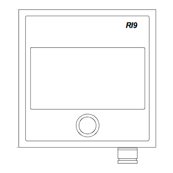
Fig. 1-1 RI9 Dimensions Installation The RI9 is designed for bulkhead or panel mounting, and should be positioned in a location in clear view of the helmsman and the ship's officers. For bulkhead mounting, use the 8 bushings enclosed with the unit. -
Page 7: Stand Alone Rudder Angle Indicator(S)
Fig. 1-3 RI9 Bulkhead mounting Stand alone rudder angle indicator(s) The RI9 indicator can be used in stand alone rudder angle indicator systems as described in sections 2 and 3 of this manual or as part of an autopilot system as described below. -
Page 8: Connection To Autopilot Junction Units
See Fig. 1-4 to Fig. 1-9 for connections to the different autopilot junction units. Fig. 1-4 RI9 in an AP50 system with RF45X The above connection diagram shows how to connect an RI9 Rudder Angle Indicator to an AP50 system with RF45X Rudder Feedback Unit. - Page 9 Instruction Manual Fig. 1-5 RI9 in a AP50 system with RF14XU The above connection diagram shows how to connect an RI9 Rudder Angle Indicator to an AP50 system with RF14XU Rudder Feedback Unit. Notes ! This configuration is for 24VDC only.
- Page 10 Simrad RI9 Rudder Angle Indicator Fig. 1-6 RI9-J45S Wiring diagram Fig. 1-7 RI9-J200S Wiring diagram Fig. 1-8 RI9-J101A Wiring diagram 20220562E...
-
Page 11: Ri9 Set-Up
RF45 and RF14XI. If the current input signal is used (RF100, RF140, RF14XI, RF45), the reference inside RI9 has to be changed. This is done by opening the RI9 and move the “jumper” ST3 from “U” to “I” position (see Fig. - Page 12 3. Move the rudder to e.g. 40 degrees (starboard or port). Use trimpot “G” (Gain) to calibrate RI9 to show the same angle as the rudder is set to (or the same angle as shown on the autopilot display in “Debug”...
- Page 13 Instruction Manual Fig. 1-11. RI9 Schematic diagram (N3-201562C) 20220562E...
-
Page 14: Maintenance
Simrad RI9 Rudder Angle Indicator Maintenance Simrad rudder indicator equipment will need no special attention besides replacing illumination bulbs (See Fig. 1-12 for location of bulbs). It is, however, essential that the mechanical linkage between the rudder stock and the shaft of the rudder feedback unit is regularly checked and maintained in good condition to avoid misalignment. -
Page 15: Rf14Xu Rudder Feedback Unit
The frequency section generates a variable frequency signal with 3400 Hz as midposition reference. This section is only used if a Simrad autopilot is connected to RF14XU. The signal varies at a rate of 20 Hz/degree, increasing when the rudder moves to port and vice versa. -
Page 16: Technical Specifications
Simrad RI9 Rudder Angle Indicator Technical specifications Dimensions:.....See Fig. 2-1 and Fig. 3-2 Protection: .......IP56 Ambient temperature:..–10 - +55°C Supply voltage:....24VDC –10%/20% Frequency section 12-40V DC Output RAI:.....Midship reference 0.5 x supply voltage Full deflection ±9V Output autopilot: 3400Hz ±20Hz/degree... -
Page 17: Installation
Fig. 2-2. RF14XU - Mounting Wiring Wiring to the RI9 is shown in Fig. 2-4 and Fig. 2-5. Fig. 2-6 - Fig. 2-8 show the combination of RI9 and Panorama connected to the RF14XU. Fig. 2-9 - Fig. 2-11 show the combination of RI9 and Panorama Mk2 connected to the RF14XU The cables are carried through cable glands and connected to the terminal board. - Page 18 Simrad RI9 Rudder Angle Indicator Fig. 2-3 Screen termination The feedback unit has an external ground terminal and must have a proper ground connection to the hull. The grounding wire should be as short as possible and at least 10 mm wide.
- Page 19 Instruction manual Fig. 2-5. RI9-RF14XI Wiring diagram VOLTAGE FB SUPPLY - SUPPLY + VOLTAGE FB SUPPLY - SUPPLY + VOLTAGE FB SUPPLY - SUPPLY + Fig. 2-6. Wiring diagram RI9, Panorama and RF14XU on 24V DC Mains 20220562E...
- Page 20 Simrad RI9 Rudder Angle Indicator VOLTAGE FB SUPPLY - SUPPLY + VOLTAGE FB SUPPLY - SUPPLY + VOLTAGE FB SUPPLY - SUPPLY + Fig. 2-7. Wiring diagram Panorama and RI9 on AC Mains using a Robertson RI4 Rectifier and “standard rudder potentiometer” 20220562E...
- Page 21 Instruction manual VOLTAGE FB SUPPLY - SUPPLY + VOLTAGE FB SUPPLY - SUPPLY + VOLTAGE FB SUPPLY - SUPPLY + Fig. 2-8 Wiring diagram Panorama and RI9 on AC Mains with regulated power supply 20220562E...
- Page 22 Simrad RI9 Rudder Angle Indicator VOLTAGE FB SUPPLY - SUPPLY + VOLTAGE FB SUPPLY - SUPPLY + VOLTAGE FB SUPPLY - SUPPLY + Fig. 2-9 Wiring diagram RI9, Panorama Mk2 and RF14XU on 24V DC Mains 20220562E...
- Page 23 Instruction manual VOLTAGE FB SUPPLY - SUPPLY + VOLTAGE FB SUPPLY - SUPPLY + VOLTAGE FB SUPPLY - SUPPLY + Fig. 2-10 Wiring diagram Panorama Mk2 and RI9 on AC Mains using a Robertson RI4 Rectifier and “Standard Rudder Potentiometer” 20220562E...
- Page 24 Simrad RI9 Rudder Angle Indicator VOLTAGE FB SUPPLY - SUPPLY + VOLTAGE FB SUPPLY - SUPPLY + VOLTAGE FB SUPPLY - SUPPLY + Fig. 2-11 Wiring diagram Panorama Mk2 and RI9 on AC Mains with regulated power supply 110/220VAC – 24VDC 2A 20220562E...
-
Page 25: Other Rudder Angles
Instruction manual Other rudder angles The RF14XU is normally delivered for ±45 degrees rudder angle (violet, brown and pink leads are not connected). For ±60 degrees, connect brown lead to terminal 10. For ±70 degrees, connect pink to terminal 10 and for ±90 degrees, connect the violet lead to terminal 10. -
Page 26: Adjustments
Simrad RI9 Rudder Angle Indicator Adjustments After having tightened all mechanical parts and connected all cables, the following adjustment must be carried out: 1. Check that the rudder is set to midship position. 2. Measure the voltage between "U" and "+", respectively "-" on the RF14XU terminal board. -
Page 27: Rf45X Rudder Feedback Unit
Instruction manual RF45X RUDDER FEEDBACK UNIT General The RF45X is a medium duty rudder feedback unit. Mechanically it is identical to it’s predecessor RF45, therefore it is a repairable rather than a potted throw away item. Electrically it outputs a frequency (pulse width modulated) signal that matches with the J3XX input (AP35/AP50), but it can also output a frequency signal (selectable via internal jumpers) that matches with AP45 and AP9 Mk3. -
Page 28: Mounting
Simrad RI9 Rudder Angle Indicator Fig. 3-1 RF45X – Dimensions Fig. 3-2 RF45/Standard Transmission Link - dimensions Mounting The RF45X is normally mounted with the shaft pointing upwards. It can, however, also be mounted with the shaft pointing downwards if that appears to be more convenient. - Page 29 Instruction manual Use the attached template (Fig. 3-6) to drill the required mounting holes. The unit is fastened to the mounting base by the two Allen screws enclosed. (Other types of screws may be used if fastened to i.e. a wooden base.) Fig.
-
Page 30: Electrical Connection
Simrad RI9 Rudder Angle Indicator Electrical connection Fig. 3-4 RF45X Internal Wiring Fig. 3-5. RI9-RF45X Wiring diagram Note ! For RF45X the supply voltage can be 12/24VDC. 20220562E... -
Page 31: Spare Parts
Instruction manual Spare parts 22011290 RF45X Rudder Feedback Unit 22011217 Mounting kit 22011365 Potentiometer 10K (with wires) 44156321 O-ring 64,5x3 mm 22011258 RF45X PCB ass’y with potentiometer (10K) 44156925 Junction box 22011183 RF45 Transmission Link, Complete 44132322 Transmission Rod M8x300mm (2) 22504054 Joint Nut M8 44157097... - Page 32 Simrad RI9 Rudder Angle Indicator 20220562E...
- Page 33 Instruction manual Fig. 3-6 RF45 Template (N4-201122 Scale 1:1 20220562E...
- Page 34 Simrad RI9 Rudder Angle Indicator 20220562E...
Need help?
Do you have a question about the RI9 and is the answer not in the manual?
Questions and answers