Table of Contents
Advertisement
Quick Links
for Near-Distance Ultrasonic Level Meters
HD500-C2
(200 kHz)
HD500-D2
(400 kHz)
Safety Precautions...................................... 2
Other Precautions....................................... 3
Preface, Checking the Accessories..........4
Names of Parts............................................ 5
Installation Method and Directions............6
for Making Connections..............................7
Description of Display................................. 8
Setting Menus..............................................9
Adjustment/Setting....................................10
switch.......................................................... 10
switch.......................................................... 11
current output.............................................12
normal LED display...................................13
Temperature display................................. 13
Carefully read this Operation Manual before using the instrument.
Store this Operation Manual in a readily accessible location.
Operation Manual
Contents
Version 3. 10 or later
Current output, ultrasonic reflection
level, and ultrasonic noise level.............. 14
Distance correction and follow-up
rate.............................................................. 15
Display unit setting, STC, and system
reset............................................................ 15
Oscillation reverberation masking time
and reversal of alarm switches................16
an error....................................................... 16
Switching the measuring mode............... 17
Setting bottom distance, Setting dam
flow route surface distance...................... 18
Setting Maximum Overflow Depth.......... 19
Setting Angle of Cut Out.......................... 20
Troubleshooting.........................................22
Specifications.............................................23
After-sales Service....................................24
Advertisement
Table of Contents

Related Manuals for Honda Electronics HD500-C2


Summary of Contents for Honda Electronics HD500-C2
-
Page 1: Table Of Contents
Operation Manual for Near-Distance Ultrasonic Level Meters Version 3. 10 or later HD500-C2 (200 kHz) HD500-D2 (400 kHz) Contents Safety Precautions........2 Current output, ultrasonic reflection Other Precautions........3 level, and ultrasonic noise level....14 Preface, Checking the Accessories..4 Distance correction and follow-up Names of Parts.......... -
Page 2: Safety Precautions
Safety Precautions This manual uses the following signs and symbols to promote safety and correct use of the product, and to prevent injury and property damage. Indicates a potentially hazardous WARNING situation that, if ignored or incorrectly handled, could result in death or serious injury. -
Page 3: Other Precautions
CAUTION Do not modify the instrument. Otherwise, electric shock may occur due to the high voltages involved. In the event of instrument failure, contact your distributor for repairs. Other Precautions Do not use the instrument near another device that uses ultrasonic waves. The instruments may interfere with each other, resulting in malfunctions. - Page 4 Honda Electronics. Honda Electronics hereby disclaims any and all liability for damages incurred by any party resulting from measurements obtained using this instrument. Checking the Accessories After receiving the product, make sure that the following accessories are contained in the package.
-
Page 5: Names Of Parts
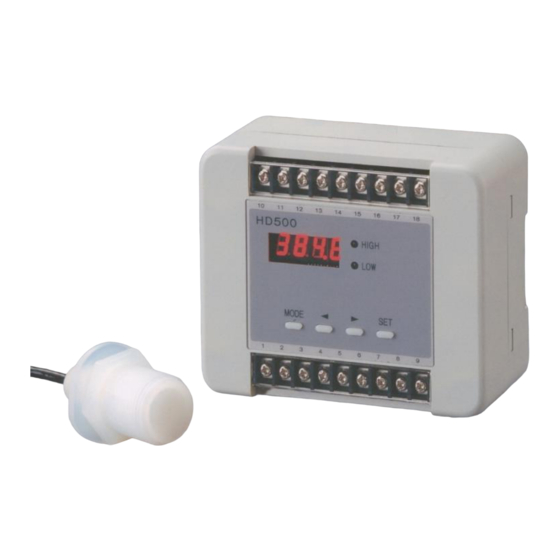
Names of Parts Display unit for distance, the rate of remaining volume, and menus Terminal board HIGH and LOW limit alarm lamps Terminal board MODE key Left key Right key SET key Dimensions 6 mm x 2 m 端 子 付 Teflon cable with terminal Hex. -
Page 6: Installation Method And Directions
Installation Method and Directions Installing the sensor Install the HD500 ultrasonic sensor horizontally on top of a tank. Make a hole with a diameter of 32 mm and a thickness of 10 mm or less on the tank. ... -
Page 7: Wiring Method And Precautions For Making Connections
Wiring Method and Precautions for Making Connections Description of the Terminals 1: Power input (0 V) 10: RS232C — Receive 2: Power input (+12 ~ 24 V) 11: RS232C — Transmit 3: Alarm switch common, F.G. 12: RS232C — GND 4: High-high limit alarm switch (HH) 13: N. -
Page 8: Description Of Display
Description of Display 156.3 Reading the display: Generally, the display unit indicates the distance or rate of the remaining volume (e.g., 156.3 mm). This indication can be switched in menu –5–. The alarm lamps and switches function according to the settings of the high-high, high, low, and low-low alarm switches, in the event of an alarm. -
Page 9: Setting Menus
Setting Menus When using a menu, press the MODE key, select a menu number using the and keys, press the SET key, and change each setting using the and keys. After completing setting, press the MODE key to exit menu setting. ... -
Page 10: Adjustment/Setting
Adjustment/Setting –0–A Setting the high-high limit alarm switch (HH) Set position C 120~1000 mm 4.7 in~3 ft 3.3 in Setting range 60~450 mm 2.3 in~1 ft 5.7 in If the liquid level exceeds the high-high limit set position, the high-high limit alarm switch is activated, lighting up the HIGH lamp (in red) simultaneously. -
Page 11: Setting The Low-Low/Low Limit Alarm Switch
–1–A Setting the low-low limit alarm switch (LL) C 120~1000 mm 4.7 in~3 ft 3.3 in Setting range D 60~450 mm 2.3 in~1 ft 5.7 in Set position If the liquid level falls below the low-low limit set position, the low-low limit alarm switch is activated, lighting up the LOW lamp (in red) simultaneously. -
Page 12: Setting The High-/Low-Limit Position Of Current Output
–2– Setting the high-limit position of current output Setting the position for a 20 mA output C 120~1000 mm 4.7 in~3 ft 3.3 in Setting range D 60~450 mm 2.3 in~1 ft 5.7 in Set the liquid level position for an output of 20 mA, in terms of the distance from the ultrasonic wave transmitting/receiving surface of the HD500. -
Page 13: Setting The Data Averaging Times/ Normal Led Display
–4– Setting the data averaging times Setting range 1~100 Set the moving average data times. Set value 1~100 Data variations Large Small Data response Quick Slow Response time 0.35 second 3.5 seconds –5– Setting LED’s usual display Setting range Select the usual display mode. Distance display (distance from the ultrasonic wave transmitting/receiving surface of the HD500) Rate of remaining volume (100.0% for the high-limit set value of current... - Page 14 –7– 4 mA current output Setting range Range cannot be set. This menu outputs a current of 4.00 mA. [Caution] The instrument outputs 4.00 mA regardless of the target distance. –8– 20 mA current output Setting range The range cannot be set. This menu outputs a current of 20.00 mA.
-
Page 15: Reset
–11– Distance correction Setting range -50.0~50.0 mm -1.96~1.96 inches Correct the target distance in units of 0.1 mm or 0.01 inch. –12– Follow-up rate Setting range 0~10.0 mm 0~0.39 inches Set the follow-up rate of the target distance. 0.01~10.0 mm 0.01~0.39 inch Follow-up rate Maximum... -
Page 16: Setting Of Current Output In The Event Of An Error
–16– Selection of oscillation reverberation masking time Setting range 0~500 This menu allows users to set the oscillation reverberation masking time. The presence of deposits on the sensor may increase oscillation reverberation. Increasing the set value causes the masking time to extend, enabling normal measurements. -
Page 17: Switching The Measuring Mode
–22– Switching the measuring mode Setting range Selection of distance measurement or dam flow rate (formula) 0=Distance measurement [Caution] Only use LED’s usual display 1~4 for distance measurements. Do not use LED’s 5 and 6. 1= Right Triangular Dam (JIS-B8302, Numachi Kurozawa, Fuchizawa formula) Requires settings -23-, -24-, -25-, -26- 2= Acute Triangular Dam (Watanabe formula) - Page 18 Requires settings -23-, -24-, -25-, -26- Fluctuation of Operations Mode 0 Mode 1 ~ 8 Item Level Measurement Dam Flow Volume Measurement 4 – 20 mA -2-, -3- setting range Maximum flow volume 20.0 mA % Display -2-, -3- setting range Maximum flow volume 100.0% Warning Switch Distance setting...
- Page 19 –23– Setting bottom distance Setting range 200.0 mm~1200.0 mm Sets the distance from the bottom surface route of dam to the sensor. (Shown as A in the figure.) –24– Setting dam flow route surface distance Setting range 10.0 mm~800.0 mm Sets the distance from the bottom surface route to the fixed point on the cut out of the dam.
-
Page 20: Setting Water Route Width Of Dam
–25– Setting water route width of dam Setting range 400.0 mm~1200.0 mm Sets the water route width of the dam. (Shown as C in the figure.) –26– Setting Maximum Overflow Depth Setting range 10.0 mm~300.0 mm Sets the maximum overflow depth of the dam. (Shown as D in the figure.) -
Page 21: Setting Angle Of Cut Out
–27– Setting Angle of Cut Out Setting range 45.0°~100.0° Sets the angle of cut out of the dam. (Shown as E in the figure.) –28– Setting width of cut out in square dam Setting range 150~5000mm Sets width of cut out in square dam. (Shown as F in the figure.) -
Page 22: Diagram: Connecting To A Computer
Diagram: Connecting to a Computer DSUB9 (DOS/V) The instrument can perform data communications using Hyper Terminal included with Windows 95 or 98 or other software. Example: $, 24.1, 390.7,0, 59, 39, Temperature, target distance, error, ultrasonic reflection level, and ultrasonic noise level Example: $,26.5, 265.3, 84.8, 10.565, 43.622, 24.2, 7.88, 1 Temperature, Measurement Range, Overflow Depth, Measured Flow, Maximum Flow Volume, Measured Flow Volume Ratio,... -
Page 23: Troubleshooting
Troubleshooting Problem Possible cause Remedy The instrument Power line not wired. Connect a 12 ~ 24 V cannot be turned Incorrect wiring DC adapter to the instrument. (No LED lights up.) Measurements The installation angle Adjust the installation cannot be made. of the sensor is angle of the sensor. -
Page 24: Specifications
Specifications HD500-C2 HD500-D2 Ultrasonic frequency 200 kHz 400 kHz External dimensions 113 x 94 x 52.5 mm 42 x 39 mm Sensor Power supply 12~24 V DC (10~28 V), 3 W (maximum) Standard measurement 120~1000 mm... -
Page 25: After-Sales Service
Please note that if the warranty card does not include the necessary information, Honda Electronics may charge fees for repairs even within the period of warranty. Requests for Repairs Always consult the Troubleshooting section of this manual when you encounter a problem. - Page 28 Headquarters: 20, Oyamazuka, Oiwa-cho, Toyohashi, Aichi, 441-3193 Tel No. +81-532-41-2511 (Main) Fax No. +81-532-41-2093 Industrial Tel No. +81-532-41-2515 (Direct) Fax No. +81-532-41- 2923(Direct) Equipment Division: e-mail: sanki@honda-el.co.jp MADE IN JAPAN Dec., 2010...
Need help?
Do you have a question about the HD500-C2 and is the answer not in the manual?
Questions and answers