Table of Contents

Related Manuals for Honda Electronics HD353-A


Summary of Contents for Honda Electronics HD353-A
- Page 1 Operation manual HD353-A (50kHz) HD353-B (100kHz) Ultrasonic level meter Read and fully understand the contents of this Operation manual before operating the product. Keep this manual so that you can check the contents anytime.
- Page 2 Foreword Thank you for purchasing this product. ■For safe operation, read and fully understand the contents of this Operation Manual before attempting to operate the equipment. ■Follow the procedure written clearly in this manual and do not take any action described as Danger, Warning and/or Precautions. If any of them is ignored, it will result in a serious incident or damage to the property and etc.
-
Page 3: Table Of Contents
Table of contents 1. Safety precautions (Must Read) ..........2 2. Components ................4 3. Names of parts ................5 4. Dimensional drawing of main unit ..........5 5. Installation and precautions ............6 6. Wiring and precautions ..............7 7. -
Page 4: Safety Precautions (Must Read)
1. Safety precautions (Must Read) The "Safety precautions" explains extremely important precautions that must be taken to prevent injury to the person using the product as well as to others and to prevent damage to property. The following is an explanation of the symbols used. . . This indicates items that if ignored could lead to serious Danger injury or death. - Page 5 Danger If abnormity of product such as fog from the product is seen, turn the power off immediately and contact our distributor for repair. Never allow water to come in contact with the product. Moreover, never place the product in a location where it will come in contact with water.
-
Page 6: Components
Warning Do not use the product at a place close to other ultrasonic device to avoid the unwanted operation due to the interrelated influence. Do not give any strong shock to the product and drop down the product. 2. Components Confirm all of followings are supplied. -
Page 7: Names Of Parts
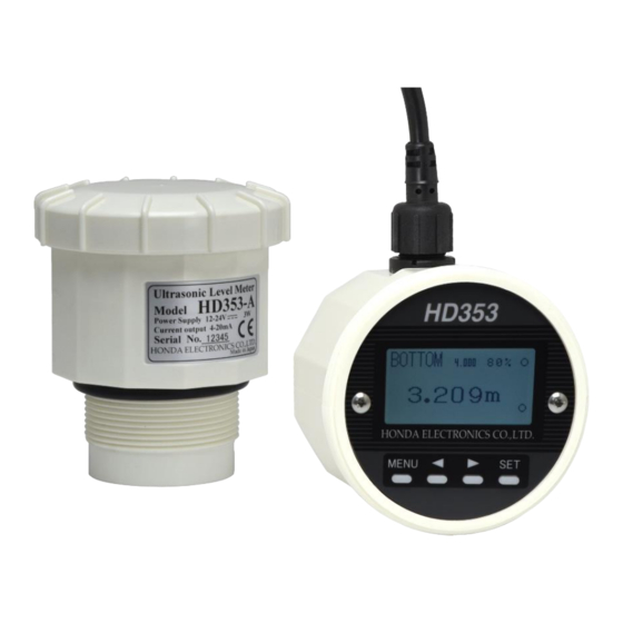
3. Names of parts Connector of distribution cable LCD window Main unit Ultrasonic transmitting surface Dimensional drawing of main unit... -
Page 8: Installation And Precautions
5. Installation and precautions ・Install HD353 on the top of tank horizontally. ・Screw in HD353 into the resin flange with G2(PF2) to the tank. ・Do not use metal nut or flange to install HD353 to the tank to avoid the incorrect measurement. -
Page 9: Wiring And Precautions
6. Wiring and precautions 12-24VDC Black Yellow White Orange Brown Green 4-20mA output Blue Shielded Red lead wire: Power source 12-24 VDC(+) Black lead wire: Power source 0V(-) Yellow lead wire: Upper limit alarm SW (Open collector output, NPN type) White lead wire: Lower limit alarm SW (Open collector output, NPN type) Orange lead wire: RS485(A+) -
Page 10: Settings According To The Tank
7. Settings according to the tank 1) Press key to indicate MENU. 2) Change the indicated parameter by keys and select the parameter by key. Change the setting value by keys. Press key again to determine the setting value. Press key not to determine the setting value. -
Page 11: Operating Instructions
8. Operating instructions Basic key operation Press key to indicate MENU. Change the indicated parameter by keys and select the parameter key. Change the setting value by keys. Press key again to determine the setting value. Press key not to determine the setting value. - Page 12 DISPMODE A - C <Level meter mode> DISPMODE A (TOP-based distance display) SW H action indication SW L action indication SW action indication; ON: ● OFF: DISPMODE B (BOTTOM-based level display) SPAN setting value DISPMODE C (% display) Rate of remaining amount in the tank Output current value Switch DISPMODE by keys.
- Page 13 DISPMODE A - C <Weir flowmeter mode> DISPMODE A (Weir flowmeter display) tF: Total flow iF: Instantaneous flow Total flow Instantaneous flow Rate of instantaneous flow DISPMODE B (BOTTOM-based level display) SPAN setting value DISPMODE C (% display) Rate of instantaneous flow Output current value...
- Page 14 DISPMODE D (Ultrasonic A mode display) Set the parameters related to the ultrasonic measurement based on the indicated waveform of ultrasonic reflections. Measured value and setting value are indicated at the bottom of display. Change the indicated parameter by keys and select the parameter key.
- Page 15 <9> FREQ: Ultrasonic frequency Setting range; HD353-A: 45 - 55kHz (1kHz step) HD353-B: 90 - 110kHz (1kHz step) Set the value so that the signal level can be larger. <10> NoiseSup: Noise suppression Setting range: 0 - 3...
-
Page 16: Setting In Menu
Fast <-> Slow Set the response speed to the measured distance change. SW H ON/OFF: HD353-A: 0 – 10m HD353-B: 0 – 5m Set the level from the tank bottom to turn ON/OFF the upper limit SW L ON/OFF: HD353-A: 0 – 10m HD353-B: 0 –... - Page 17 4mA OFST: 0 – SPAN or lower “4mAOFST=0” means that the tank bottom is the distance/level of 4mA output. [Caution] If “4mAOFST” is any other than 0, “4mAOFST” to “SPAN” is 4- 20mA output range. I4-20: Norm(Normal) or Reve(Reverse) Set the basis of 4-20mA output. Normal: 4mA = 0%, 20mA = 100% Reverse: 20mA = 0%, 4mA = 100% *If any other than 0 is set to [4mA OFST], OFFSET works at 0% side.
-
Page 18: Weir Flowmeter Setting
10. Weir flowmeter setting FLOWmod: Selection of Weir flowmeter function OFF: Level meter mode Others: Weir flowmeter mode Level meter mode: OFF 90 deg V-notch weir: 90ang Arbitrary V-notch weir: AngleV... - Page 19 Contracted rectangular weir: Squar1 Suppressed rectangular weir: Squar2 Parshall flume flowmeter <-> PF-1(1inches) <-> PF-2(2inches) <-> PF-3(3inches) <-> PF-6(6inches) <-> PF-9(9inches) <-> PF-10(1feet) <-> PF-15(1.5feet) <-> PF-20(2feet) <-> PF-30(3feet) <-> PF-40(4feet) <-> PF-50(5feet) <-> PF-60(6feet) <-> PF-70(7feet) <-> PF-80(8feet)
- Page 20 FBZERO: Distance from the ultrasonic transmitting surface to the channel floor Setting range: 0.3 - 5m FSPAN: Max. overflow level Setting range: 0.05 - 3m Max. measurable flow depends on FSPAN. While FSPAN is set, Max. measurable flow is showed at the bottom of display as “MaxFlow=XX.XXm B WIDTH: Channel width Setting range: 0.4 - 32m...
-
Page 21: Setting Parameters
Selectable item A TopDis B BotDis DISPMODE Display mode C Percen D Echo Distance from the HD353-A: 0.5 - 10 ultrasonic B ZERO HD353-B: 0.25 - 5 transmitting surface Unit [m] to the tank bottom HD353-A: 0 - 10 Level from 0% to... - Page 22 Setting range Parameter Explanation Selectable item RS485 RS485 No. 1-99 MODBUS NO. 2400, 4800, 9600, Baud rate for RS485 485BAUD 19200, 38400, communication 57600 or 115200 Parity check for NONE, ODD, or PARITY RS485 EVEN communication As “Weir flowmeter Weir flowmeter FLOWmod setting”...
-
Page 23: Connection To The Computer (Rs485)
12. Connection to the computer (RS485) Specifications of RS485 Communication protocol MODBUS(RTU) Electrical characteristics Compliant with EIA RS485 2 wire and half-duplex Communication method (Poling/selecting) Synchro system asynchronous method Selectable from 2400, 4800, 9600, 19200, Baud rate 38400, 57600 or 115200 Start bit 1 bit Data length... -
Page 24: Rs485 Modbus Communication Format
13. RS485 MODBUS communication format 1: In case of no incoming command for 3.5-character-time, HD1200 recognizes the completion of incoming command and the command processing is done. 2: Unit address can be selected from 1 to 99. MODBUS RTU command message frame CRC CHECK START ADDRESS... - Page 25 Command = 03 Readout of holding register, Command = 06 Write of holding register Query(03,06) Slave Address Function Starting Address Hi Lo No. of Points Hi Lo Response(03) Slave Address Function Byte Count Data n Hi Lo Data n+1 Hi Lo Response(06) Slave Address Function...
-
Page 26: Specifications
14. Specifications Model HD353-A HD353-B Ultrasonic frequency 50kHz 100kHz External dimensions Dia. 93 x 110mm Rated power source 12 - 24VDC Permissible power +/- 10% of Rated power source source range Max. power 3W or lower consumption Output current 4-20mA +/- 0.02mA DC... -
Page 27: After-The-Sale-Service
15. After-the-sale-service ◆When after-the-sale-service is required, please contact the seller of product or the manufacturer with the detailed information about the malfunction. - Page 28 Industrial Equipment Div. 20, Oyamazuka, Oiwa-cho, Toyohashi, Aichi, 441-3193, Japan TEL: +81-532-41-2774 FAX: +81-532-41-2923 URL: http://www.honda-el.co.jp/en/ Bangkok representative office Room 23, 2 Jasmine Bldg., 12 Fl., Soi Sukhumvit 23(Prasanmitr), Sukhumvit Rd., North Klongtoey, Wattana,Bangkok 10110 TEL: +66-2-612-7311 FAX: +66-2-612-7399 MADE IN JAPAN January, 2018...
Need help?
Do you have a question about the HD353-A and is the answer not in the manual?
Questions and answers