
Related Manuals for Honda Electronics HD320


Summary of Contents for Honda Electronics HD320
- Page 1 Operation manual HD320 Ultrasonic level meter Read and fully understand the contents of this Operation manual before operating the product. Keep this manual so that you can check the contents anytime.
- Page 3 Foreword Thank you for purchasing this product. ■For safe operation, read and fully understand the contents of this Operation Manual before attempting to operate the equipment. ■Follow the procedure written clearly in this manual and do not take any action described as Danger, Warning and/or Precautions. If any of them is ignored, it will result in a serious incident or damage to the property and etc.
-
Page 4: Table Of Contents
Table of contents 1. Safety precautions (Must Read) ..........2 2. Components ................4 3. Names of parts ................. 5 4. Dimensional drawing of main unit ..........5 5. Installation and precautions ............6 6. Wiring and precautions ............. 7 7. -
Page 5: Safety Precautions (Must Read)
1. Safety precautions (Must Read) The "Safety precautions" explains extremely important precautions that must be taken to prevent injury to the person using the product as well as to others and to prevent damage to property. The following is an explanation of the symbols used. . . This indicates items that if ignored could lead to serious Danger injury or death. - Page 6 Danger If abnormity of product such as fog from the product is seen, turn the power off immediately and contact our distributor for repair. Never allow water to come in contact with the product. Moreover, never place the product in a location where it will come in contact with water.
-
Page 7: Components
Do not give any strong shock to the product and drop down the product. 2. Components Confirm all of followings are supplied. If any of followings is missed, contact the distributor. HD320 (Main unit) Distribution cable 10m Operation Manual... -
Page 8: Names Of Parts
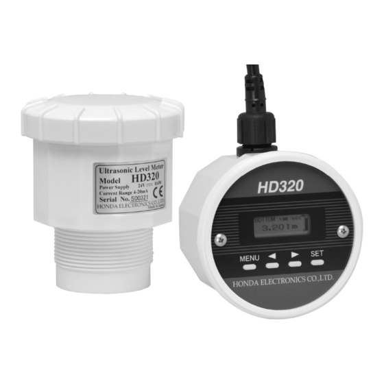
3. Names of parts Connector of distribution cable LCD window Main unit Ultrasonic transmitting surface Dimensional drawing of main unit... -
Page 9: Installation And Precautions
・ S crew in HD320 into the resin flange with G2(PF2) to the tank. ・ D o not use metal nut or flange to install HD320 to the tank to avoid the incorrect measurement. Use the resin nut or flange to install HD320 to the tank. -
Page 10: Wiring And Precautions
White lead wire Power source DC + Black lead wire Power source DC - [CAUTION] HD320 doesn’t operate at all if polar characters, + and -, are reversed. 電 源 電 圧 と 最 大 負 荷 抵 抗 の 関 係... -
Page 11: Settings According To The Tank
7. Settings according to the tank 1) Press key to indicate MENU. 2) Change the indicated parameter by keys and select the parameter by key. Change the setting value by keys. Press key again to determine the setting value. Press key not to determine the setting value. -
Page 12: Operating Instructions
8. Operating instructions Basic key operation Press key to indicate MENU. Change the indicated parameter by keys and select the parameter key. Change the setting value by keys. Press key again to determine the setting value. Press key not to determine the setting value. - Page 13 DISPMODE A – C <Level meter mode> DISPMODE A (TOP-based distance display) Rate of remaining amount in the tank DISPMODE B (BOTTOM-based level display) SPAN setting value DISPMODE C (% display) Rate of remaining amount in the tank Output current value Switch DISPMODE by keys.
- Page 14 DISPMODE A – C <Weir flowmeter mode> DISPMODE A (Weir flowmeter display) t F : Total flow i F : Instantaneous flow Total flow Instantaneous flow Rate of instantaneous flow DISPMODE B ( B OTTOM-based level display ) SPAN setting value DISPMODE C (% display) Rate of instantaneous flow Output current value...
- Page 15 DISPMODE D (Ultrasonic A mode display) Set the parameters related to the ultrasonic measurement based on the indicated waveform of ultrasonic reflections. Measured value and setting value are indicated at the bottom of display. Change the indicated parameter by keys and select the parameter key.
- Page 16 <4> maskP: Start position of rectangular mask <5> maskW: Rectangular mask width <6> maskLv: Rectangular mask level Settings of rectangular mask to avoid the undesired reflections from an obstacle within the measuring range. <7> Fmask: Reverb mask width Reverb mask width should be wider to avoid incorrect measurement when the oscillation reverb is too long.
- Page 17 <9> FREQ: Ultrasonic frequency Setting range: 45 - 55kHz (1kHz step) Set the value so that the signal level can be larger. <10> dADJ: Distance adjustment Setting range: -50 - +50mm dADJ is the same as -12- Dist Adj in MENU.
-
Page 18: Setting In Menu
9. Setting in MENU Press key to indicate MENU. Press key again to escape from MENU. After no key operation for 3 min., the display returns to the main display, automatically. DISPMODE: A - D Select the appropriate one. B ZERO: 0.5 - 10m Set the distance from the ultrasonic transmitting surface to the tank bottom or the channel floor. - Page 19 BRIGHT: OFF <-> AUTO <-> ON Set the back light function. AUTO: ON for 10 min. after power power-on, OFF after 10 min. passes 1 hour: ON for 1 hour after any key operation, OFF after 1 hour passes 4-20SET: normal <-> i4mA - i20mA Parameter for the connection test of 4-20mA output.
-
Page 20: Weir Flowmeter Setting
10. Weir flowmeter setting FLOWmod: Selection of Weir flowmeter function OFF: Level meter mode Others: Weir flowmeter mode Level meter mode: OFF 90 deg V-notch weir: 90ang Arbitrary V-notch weir: AngleV... - Page 21 Contracted rectangular weir: Squar1 Suppressed rectangular weir: Squar2 Parshall flume flowmeter <-> PF-1(1inch) <-> PF-2(2inch) <-> PF-3(3inch) <-> PF-6(6inch) <-> PF-9(9inch) <-> PF-10(1feet) <-> PF-15(1.5feet) <-> PF-20(2feet) <-> PF-30(3feet) <-> PF-40(4feet) <-> PF-50(5feet) <-> PF-60(6feet) <-> PF-70(7feet) <-> PF-80(8feet)
- Page 22 FBZERO: Distance from the ultrasonic transmitting surface to the channel floor Setting range: 0.3 - 5m FSPAN: Max. overflow level Setting range: 0.05 - 3m Max. measurable flow depends on FSPAN. While FSPAN is set, Max. measurable flow is showed at the bottom of display as “MaxFlow=XX.XXm B WIDTH: Channel width Setting range: 0.4 - 32m...
-
Page 23: Setting Parameters
11. Setting parameters Setting range Parameter Explanation Selectable item A TopDis B BotDis DSPMODE Display mode C Percen D Echo Distance from ultrasonic 0.5 - 10 B ZERO Unit [m] transmitting surface to the tank bottom Level from 0% to 0 - 10 SPAN Unit [m]... - Page 24 Setting range Parameter Explanation Selectable item 0.4 - 32 B WIDTH Channel width Unit [m] Height from 0.001 - 3.5 D SPAN channel floor to the Unit [m] lower edge of weir Cutout width 0.15 - B WIDTH sbWIDTH contracted Unit [m] rectangular weir Arbitrary angle of V-...
-
Page 25: Specifications
12. Specifications Model HD320 Ultrasonic frequency 50kHz External dimensions Dia. 93 x 110mm Rated power source 24VDC Permissible power +/- 10% of Rated power source source range Max. power 0.6W or lower consumption Output current 4-20mA +/- 0.02mA DC Additional function... -
Page 26: After-The-Sale-Service
13. After-the-sale-service W hen after-the-sale-service is required, please contact the seller of ◆ product or the manufacturer with the detailed information about the malfunction. - Page 28 Industrial Equipment Div. 20, Oyamazuka, Oiwa-cho, Toyohashi, Aichi, 441-3193, Japan TEL: +81-532-41-2774 FAX: +81-532-41-2923 URL: http://www.honda-el.co.jp/en/ Bangkok representative office Room 23, 2 Jasmine Bldg., 12 Fl., Soi Sukhumvit 23(Prasanmitr), Sukhumvit Rd., North Klongtoey, Wattana,Bangkok 10110 TEL: +66-2-612-7311 FAX: +66-2-612-7399 MADE IN JAPAN September, 2015...
Need help?
Do you have a question about the HD320 and is the answer not in the manual?
Questions and answers