Advertisement
Table of Contents
COMMUNICATIONS, INC.
PUBLIC ADDRESS
CTS-1035, CTS-1060
AMPLIFIERS
AND CTS-1100
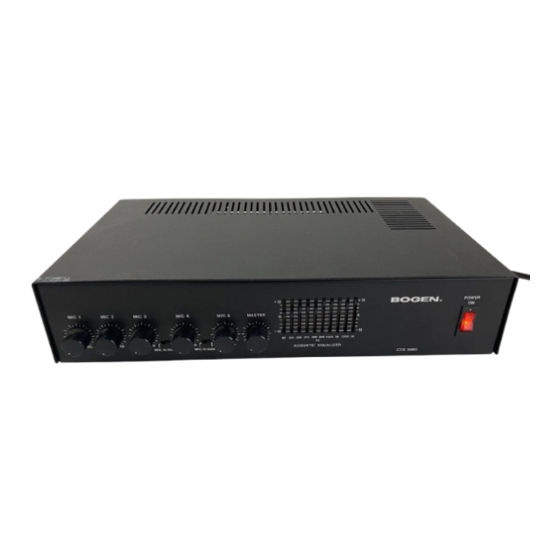
DESCRIPTION
The Bogen Models CTS-1035, CTS-1060, and CTS-1100 are public
address amplifiers designed for use in high-quality sound systems.
They combine advanced solid-state design with versatile operating
features and the flexibility to meet a wide range of application re-
quirements.
Eath CTS-Series amplifier mixes five input signals; either five low-
impedance microphones, or a combination of microphone and
auxiliary inputs. Switches are used to select MIC 4/AUX1 and/or
MIC 5/AUX 2 operation. Precedence circuitry is provided for the
MIC/AUX charmels, An intemaljumper configuration activates a
phantom power supply for condenser microphones. Automatic
Level Control (ALC) circuitry compensates for different micro¬
phone techiuques and assures a uniform output level.
A 2/3-octave equalizer permits boosting or attenuating any of 10
selected frequencies to eliminate feedback, improve intelligibility
and increase usable power. Each equalizer slide control has a
detented flat position.
Microphone input is via screw-terminal strips; standard Hi-Z
phono jacks for the auxiliary inputs accept a tuner, tape/cassette
player, line-matching transformer, or tone generator.
An output terminal strip provides standard balanced or unbalanced
speaker taps, as well as connections for 25V, 25VCT, and 70V
speaker lines. A TAPE OUT jack permits recording the output of
the amplifier independent of the master volume or equalizer Con¬
trols. A PWR AMP jack permits feeding the output of the CTS
amplifier to apower amplifier. The use of an accessory transformer,
Model WMT-1A, permits feeding a signal from a 500
j
600-ohm
telephone line into the amplifier, or connects the output of the
amplifier to a 500/600-ohm telephone line. Remote volume con¬
trol of the output is possible with the RVC-CTS accessoiy.
The amplifier operates from a 120-volt, 60Hz source. The power
switch illuminates in the "on" position. A three-prong line cord
automatically grounds the amplifier when connected to a properly
grounded three-wire outlet. Output transistors are prntecred hy a
thermal breaker; circuitry is further protected by a resettable
Cir¬
cuit breaker.
The CTS amplifiers mount easily in standard equipment racks,
usrng an optional rack panel kit. Model RPK-52.
INSTALLATION
UNPACKING
The amplifier was carefully checked before leaving the factory. In-
spect the shipping container and unit carefully for indications of
improper handling. If the amplifier is damaged, place an immediate
claim witn tue distributor trom whom it was purchased. If the
amplifier was shipped to you, place a claim with the carrier in ac-
cordance with Federal ICC Regulations.
POWER AND GROUNDING
The amplifier is supplied with a line cord terminated in a three-
prong plug. The line cord must be plugged into a properly grounded
outlet providing nominal 120-volt, 60Hz AC. Outlet adaptors may
be used
provided that the grounding pigtail
on
the adaptor
is
properly connected to ground.
INPUT CONNECTIONS
CAUTION
Thefollowing installation instructions are for use by quali
-
fed service personnet only. To avoid an clc^l/ic shocJc,
do
not perform any funetions requiring removal of the cover
of the amplifier unless you are qualified to do so.
LOW-lMPEDANCE BALANCED MICROPHONES
The amplifier is designed for direct connection of low-impedance
balanced microphones to the screw terminal strips on the rear
panel. The microphone lead should be a two-conductor shielded
cable. Connect the cable shield to the GND terminal.
CONDENSER MICROPHONES
To supply power for condenser microphones, connect the jumper
as indicated in Note 3 on the schematic diagram.
Note
When phantom power is enabled, power is supplied to all
five microphone inputs (does not affectAUX inputs); there-
fore, use
condenser microphones only
when usingphan¬
tom power
REMOTE CONTROL
PRECEDENCE
Precedence circuits are available to mute MIC 4/AUX 1 and/or
MIC 5/AUX 2. A customer-supplied SPST switch with normally-
open contacts is required for this funetion and is connected to the
desired REMOTE CONTROL PREC terminals
on the rear panel.
REMOTE VOLUME CONTROL
The Bogen RVC-CTS accessory provides remote volume control
of the overall output of the amplifler. Connect the accessory to the
REMOTE CONTROL PREC terminals labelled MASTER.
AUX1 AND AUX 2
Front panel switches are provided to select MIC 4 or AUX 1 opera¬
tion and MIC 5 or AUX 2 operation. The AUX inputs use stan¬
dard Hi-Z phono jacks and accept input from a high-level source
such as a tuner, cassette-tape player, WMT-1A telephone line-
matching transformer, or tone generator. Use single-conductor
shielded cable terminated in an RCA phono plug for connecting
auxiliary equipment.
Printed In U.S.A. 8906 54-5692-02
Advertisement
Table of Contents


Need help?
Do you have a question about the CTS-1035 and is the answer not in the manual?
Questions and answers