Advertisement
Quick Links
®
Please read and save these instructions for future reference. Read carefully before attempting to assemble, install,
operate or maintain the product described. Protect yourself and others by observing all safety information. Failure
to comply with these instructions will result in voiding of the product warranty and may result in personal injury
and/or property damage.
Installing an RRL/OCI on a Combination Fire Smoke Damper:
1) Use a hole saw to drill a 3
Detail 2). See chart on page 2 for location of hole.
2) Attach indicator bracket to blade. For an airfoil blade dampers, use existing
holes in blade (Detail 1-A). For a 3V blade damper, drill two 0.166 in. (4 mm)
holes (Detail 1-B). Fasten bracket to blade with #10 x
self-drilling screws (or equivalent).
3) Fit indicator link into blade bracket (Detail 1-C).
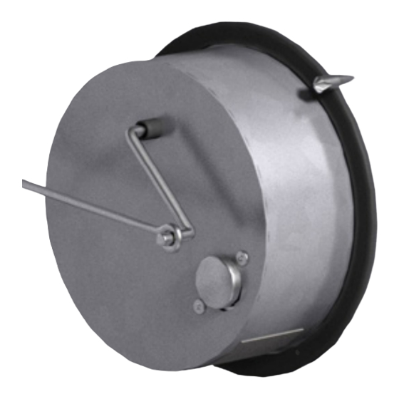
4) Insert RRL/OCI unit through hole in sleeve (round end inside).
5) Place 4 in. x 4 in. J-box over the flange of the RRL/OCI unit and align holes.
6) Mount control box to sleeve/sideplate with #10-16 x
self-drilling screw or equivalent (Detail 1-D).
Upturned Leg Faces
Away Fr o m Blade End
7) Place one push nut on the switch wire. Place indicator link on switch wire and secure with a second push nut
#10 x 1/2 in. T ek Screw
or Equivelant
(Detail 1-D).
Part No. 415555
8) Complete wiring and install J-box cover.
A
Upturned Leg Faces
Away Fr o m Blade End
#10 x 1/2 in. T ek Screw
or Equivelant
Part No. 415555
2 Req'd
Indicator
Link
A
Airfoil Blade
Note: Indicator Link Part Nos
For Standard Sleeve (short): 457808
For Extended Sleeve (long): 457801
Indicator
Link
Note: Indicator Link Part Nos
For Standard Sleeve (short): 457808
For Extended Sleeve (long): 457801
Indicator Bracket
Part No. 658594
1 Req'd
Detail 1
Airfoil Blade
®
Installation, Operation and Maintenance Manual
⁄
in. (92 mm) diameter hole in sleeve (Page 2,
5
8
Indicator Bracket
Part No. 658594
1 Req'd
2 Req'd
Airfoil Blade
Indicator Bracket
Part No. 658594
1 Req'd
C
Indicator
Bracket
.
RRL/OCI - Exploded View
C
Indicator
Bracket
.
Upturned Leg
Faces Away From
Blade End
#10 x 1/2 in. Tek
Screw
Indicator Bracket
or Equivelant
RRL/OCI - Exploded View
⁄
in. (13 mm)
1
2
RRL/OCI - Exploded View
⁄
in. (19 mm)
3
4
Upturned Leg
Faces Away From
Blade End
#10 x 1/2 in. Tek
Screw
Indicator Bracket
or Equivelant
Part No. 658594
Part No. 415555
1 Req' d
2 Req'd
B
Upturned Leg
Faces Away From
0.166 in. dia.
Blade End
2 Places
#10 x 1/2 in. Tek
3-V Blade
Screw
Indicator Bracket
or Equivelant
Part No. 658594
Part No. 415555
1 Req' d
2 Req'd
B
D
1.750
0.166 in. dia.
2 Places
3-V Blade
Gasket
1 Req'd
Push Nuts
2 Req'd
Indicator Link
(short or long; see C)
1 Req'd
on FSD, SEFSD, SSFSD Series
D
Upturned Leg Faces
Away Fr o m Blade End
#10 x 1/2 in. T ek Screw
or Equivelant
Part No. 415555
2 Req'd
Gasket
D
A
1 Req'd
Push Nuts
2 Req'd
Indicator Link
(short or long; see C)
1 Req'd
Indicator
Link
Gasket
1 Req'd
Push Nuts
2 Req'd
Indicator Link
(short or long; see C)
1 Req'd
Note: Indicator Link Part Nos
1.750
For Standard Sleeve (short): 457808
For Extended Sleeve (long): 457801
#10-16 x 3/4 in .
SIHWH Screw
2 Req'd
J-Box Cover
1 Req'd
J-Box
1 Req'd
RRL/OCI
1 Req'd
Document 471836
RRL/OCI Kits
#10-16 x 3/4 in .
SIHWH Screw
2 Req'd
J-Box Cover
Indicator Bracket
1 Req'd
Part No. 658594
J-Box
1 Req'd
#10-16 x 3/4 in .
1 Req'd
SIHWH Screw
RRL/OCI
2 Req'd
1 Req'd
Airfoil Blade
J-Box Cover
1 Req'd
J-Box
1 Req'd
RRL/OCI
1 Req'd
C
Indicator
Bracket
.
RRL/OCI IOM
1
Upturn
Faces Away
Blad
#10 x 1/2 in
S
or Equiv
Part No. 41
2 R
B
0.166 in. d
2 Pla
Advertisement

Related Manuals for Greenheck RRL/OCI


Summary of Contents for Greenheck RRL/OCI
- Page 1 4) Insert RRL/OCI unit through hole in sleeve (round end inside). Away Fr o m Blade End #10 x 1/2 in. T ek Screw J-Box Cover 5) Place 4 in. x 4 in. J-box over the flange of the RRL/OCI unit and align holes. Indicator Bracket or Equivelant 1 Req’d Part No.
- Page 2 As a result of our commitment to continuous improvement, Greenheck reserves the right to change specifications without notice. Product warranties can be found online at Greenheck.com, either on the specific product page or in the literature section of the website at Greenheck.com/Resources/Library/Literature.
Need help?
Do you have a question about the RRL/OCI and is the answer not in the manual?
Questions and answers