Table of Contents
Advertisement
Quick Links
®
Installation, Operation and Maintenance Manual
Please read and save these instructions for future reference. Read carefully before attempting to assemble, install,
operate or maintain the product described. Protect yourself and others by observing all safety information. Failure
to comply with these instructions will result in voiding of the product warranty and may result in personal injury
and/or property damage.
These instructions apply to 1
fire smoke dampers mounted in: 1) masonry, block, or
stud walls and 2) concrete floors. Specific requirements
in these instructions are mandatory. Dampers must be
installed in accordance with these instructions to meet
the requirements of UL 555 and UL 555S.
Note: Combination fire smoke dampers are
manufactured and labeled for either vertical or
horizontal installation. The dampers must be installed in
accordance with labeling.
Receiving and Handling
Upon receiving dampers, check for both obvious
and hidden damage. If damage is found, record all
necessary information on the bill of lading and file
a claim with the final carrier. Check to be sure that
all parts of the shipment, including accessories, are
accounted for.
Dampers must be kept dry and clean. Indoor storage
and protection from dirt, dust, and the weather is
highly recommended. Do not store at temperatures in
excess of 100°F (38°C).
SAFETY WARNING
Improper installation, adjustment, alteration, service
or maintenance can cause property damage, injury
or death. Read the installation, operating, and
maintenance instructions thoroughly before installing
or servicing this equipment.
®
⁄
hour rated combination
1
2
Grille Access Out of Wall or Out of Floor
Combination Fire Smoke Damper
Table of Contents
General Information . . . . . . . . . . . . . . . . . . 2
Installation Supplements. . . . . . . . . . . . . . . . 2
Electrical Guidelines . . . . . . . . . . . . . . . . . . 2
Pre-Installation Guidelines . . . . . . . . . . . . . . . 2
Preparation of Openings . . . . . . . . . . . . . . . . 3
Floor Openings. . . . . . . . . . . . . . . . . . . . . 4
Inserting Dampers Into Wall/Floor Openings . . . . . 5
Openings . . . . . . . . . . . . . . . . . . . . . . . . 6
Duct to Sleeve Connection . . . . . . . . . . . . . . 6
Approved Breakaway Connections . . . . . . . . . . 7
Connections . . . . . . . . . . . . . . . . . . . . . . 9
Damper Maintenance . . . . . . . . . . . . . . . . .10
Damper Troubleshooting . . . . . . . . . . . . . . . .10
Notes . . . . . . . . . . . . . . . . . . . . . . . . . .11
Document 472477
GFSD Series
GFSD Series
1
Advertisement
Table of Contents

Subscribe to Our Youtube Channel
Related Manuals for Greenheck GFSD Series


Summary of Contents for Greenheck GFSD Series
-
Page 1: Table Of Contents
Grille Access Out of Wall or Out of Floor Combination Fire Smoke Damper ® GFSD Series Installation, Operation and Maintenance Manual Please read and save these instructions for future reference. Read carefully before attempting to assemble, install, operate or maintain the product described. Protect yourself and others by observing all safety information. Failure to comply with these instructions will result in voiding of the product warranty and may result in personal injury and/or property damage. -
Page 2: General Information
Verify power before wiring actuator. (annular space). However, caulking may be applied to Greenheck is not responsible for any damage to, or the retaining angles. failure of the unit caused by incorrect field wiring. To 7) ACCESS: Suitable access (such that RRL’s and... -
Page 3: Preparation Of Openings
Metal stud only Second set of studs are not required on openings Figure 2 36 in. x 36 in. (914mm x 914mm) or smaller. Ceiling Runner Detail 24 in. (610mm) O.C. Max. Floor Runner Figure 2A GFSD Series Metal stud only ®... -
Page 4: Clearances Required Between Damper Sleeves & Wall/Floor Openings
On continuous duct installations the retaining angles must overlap the wall/floor by 1 in. (25 mm). No clearances are required between the wall/floor opening and the sleeve. Note that the dampers may not be installed in the plane of the wall using this installation method. GFSD Series ®... -
Page 5: Inserting Dampers Into Wall/Floor Openings
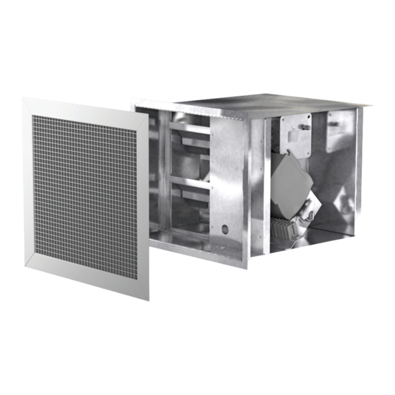
Figure 5: Through the Grille - Duct Terminates Actuator Factory Supplied Thermal Blanket Compartment 3 1/2 in. Max. Masonry floor Electrical Access Combination fire smoke damper Panel Figure 6: Continuing Duct - Horizontal or Vertical Mount Figure 7: GFSD front view GFSD Series ®... -
Page 6: Securing The Damper/Sleeve Assembly To Wall/Floor Openings
The size of the damper/duct determines the required sleeve gauge and the required duct to sleeve connection (see table on next page). The sleeve thickness must also not be less than the gauge of the connecting duct. Any duct connection other than the breakaway connections described below are considered rigid. GFSD Series ®... -
Page 7: Approved Breakaway Connections
(see Figure 11) on the sides. Plain “S” Slip Hemmed “S” Slip Double “S” Slip Drive Slip Joint Figure 11 Inside Slip Joint Standing “S” Standing “S” (Alt.) Standing “S” (Alt.) Standing “S” Standing “S” (Bar Reinforced) (Angle Reinforced) Figure 10 GFSD Series ®... - Page 8 6 in. long metal cleat or 1/16 in. max. thickness plastic cleat; 12 in. c-c (min. 1 per side) Flanged system angles (Attach per manufacturer's instructions) 3/8 in. bolts in corners are optional Neoprene or Butyl gasket between all angles Duct Figure 13 GFSD Series ®...
- Page 9 Connection Connection Butyl Gasket Damper Sleeve Butyl Gasket Damper Sleeve Figure 23: Metal cleat method Figure 24: Screw method Metal cleat Spot weld or Tek screw per TDC or TDF manufacturer instructions Connection Butyl Gasket Damper Sleeve GFSD Series ®...
-
Page 10: Actuator And Temperature Response Device Connections
The switch provides a positive open and closed signal when used in conjunction with remote indicator lights. See Figure 19 for wiring of the TOR thermostats and indicator switches. CLOSED OPEN Figure 27: TOR wiring diagram GFSD Series ®... -
Page 11: Damper Maintenance
Clean with a non-oil based solvent (see Damper Maintenance) RRL or TOR sensor Heat Push reset button located on backside of RRL or TOR tripped Damper does not No power supplied to the actuator Add power supply operate GFSD Series ®... - Page 12 As a result of our commitment to continuous improvement, Greenheck reserves the right to change specifications without notice. Product warranties can be found online at Greenheck.com, either on the specific product page or in the literature section of the website at Greenheck.com/Resources/Library/Literature.
Need help?
Do you have a question about the GFSD Series and is the answer not in the manual?
Questions and answers