
Subscribe to Our Youtube Channel
Related Manuals for Giacomini K282K


Summary of Contents for Giacomini K282K
- Page 1 Kit for stand-alone management for HVAC systems with fixed point regulation K282K Installation and operating manual Read carefully before installation, commissioning and operation...
-
Page 2: Table Of Contents
CONTENT Safety Instructions EU-Conformity General Instructions Explanation of Symbols Changes to the Unit Warranty and Liability Disposal and Pollutants Description K282K Technical Data About the Controller Scope of Supply Hydraulic Variants Installation Electrical terminal Wall Installation Electrical Connection Installing the Temperature Sensors... -
Page 3: Safety Instructions
Safety Instructions EU-Conformity By affixing the CE mark to the unit the manufacturer declares that the K282K conforms to the following relevant safety regulations: EU low voltage directive 2014/35/EU EU electromagnetic compatibility directive 2014/30/EU conforms. Conformity has been verified and the corresponding documentation and the EU declaration of conformity are kept on file by the manufacturer. -
Page 4: Changes To The Unit
Changes to the Unit Changes, additions to or conversion of the unit are not permitted without written permission from the manufacturer. It is likewise forbidden to install additional components that have not been tested together with the unit. If it becomes apparent that safe operation of the unit is no longer possible, for example due to damage to the housing, the unit must be taken out of operation immediately. -
Page 5: Description K282K
About the Controller The Heating controller K282K facilitates efficient use and function control of your Heating system possible while its handling is intuitive. After every input step the suitable functions are matched to the keys and explained in a text above. In the menu 'measurement values and settings' are help text and graphics in addition to key words. -
Page 6: Hydraulic Variants
Hydraulic Variants The following illustrations should be regarded only as schematic representations of the respective hydraulic systems and do not claim to be complete. Under no circumstances should the controller replace any safety devices. Depending on the specific application, additional system and safety components such as check valves, non-return valves, safety temperature limiters, scalding protectors, etc., may be required. -
Page 7: Wall Installation
Wall Installation 1. Unscrew cover screw completely. 2. Carefully pull upper part of housing from lower part. 3. Set upper part of housing aside. Do not touch the electronics. 4. Hold the lower part of the housing up to the selected position and mark the two mounting holes. -
Page 8: Installing The Temperature Sensors
Installing the Temperature Sensors The controller operates with Pt1000 temperature sensors which are accurate to 1 °C, ensuring optimal control of system functions. If desired, the sensor cables can be extended to a maximum of 30 m using a cable with a cross-section of at least 0.75 mm². Ensure there is no contact resistance! Position the sensor precisely in the area to be measured! Only use immersion, pipe- mounted or flat-mounted sensors suitable for the specific area of application with the appropriate permissible temperature range. -
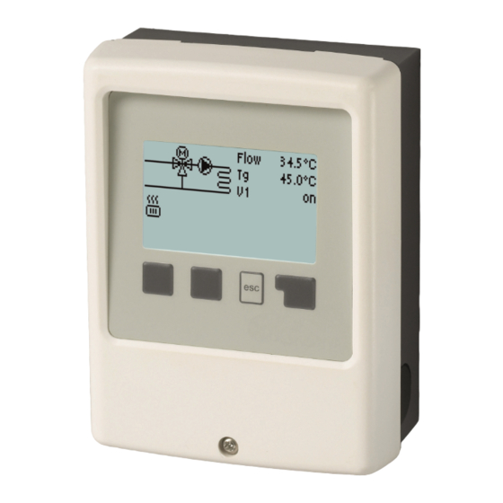
Page 9: Operation
Operation Display and Input The display‘s (1), extensive text and graphical mode, enables simple, almost self-explanatory, operation of the controller. Entries are made using 4 keys (2+3), to which contextual functions are assigned. The ‚esc‘ key (3) is used to cancel an entry or to exit a menu. -
Page 10: Timer
1. Timer Settings for time, date and operating times for the heating circuit. The associated temperature reference values are specified in Menu 5, ‚Settings‘. Time & Date Serve to set the current time and date. For time-dependent functions such as circulation and anti-legionella and the evaluation of system data, it is essential that the time is accurately set on the controller. -
Page 11: Service Values
2. Service Values Serve for remote diagnosis by a specialist or the manufacturer in the event of errors, etc. Enter the values into the table when an error occurs. 3. Settings By no means does the controller replace the safety appliances on site! Heating Circuit Reference Manual default value for the set flow temperature. -
Page 12: Appendix
Appendix Example for signal settings Technical data PWM and 0-10V... - Page 13 D - 58300 Wetter (Ruhr) This pamphlet is merely for information purposes. +49 (0)2335 682 77 0 Giacomini S.p.A. retains the right to make modifications for technical or +49 (0)2335 682 77 10 commercial reasons, without prior notice, to the items described in this info@sorel.de...
Need help?
Do you have a question about the K282K and is the answer not in the manual?
Questions and answers