Table of Contents
Advertisement
Quick Links
T
- T
ermoregolazione
0937ML Ottobre 2017 - October 2017
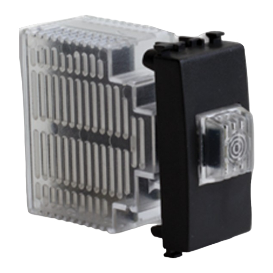
S
onda cieca temperatura e umidità
F
-
lush
mounting temperature and humidity ambient probe
K493i
Descrizione - Description
La sonda ambiente K493I permette il controllo degli impianti di riscaldamento
e/o raffrescamento in combinazione con il modulo di regolazione KPM30
o KPM31. La sonda deve essere collegata al modulo di regolazione KPM30
o KPM31 mediante Modbus; tramite il Bus la sonda comunica i valori di
temperatura e umidità relativa dell'ambiente in cui è installata.
La sonda K493I può svolgere la funzione di termostato ambiente cieco
nelle applicazioni in cui non è necessario alcun elemento di comando o di
visualizzazione per l'utente. Nel funzionamento come termostato ambiente
cieco, la visualizzazione e l'impostazione della temperatura ambiente misurata
e desiderata, possono essere effettuate centralmente per mezzo del display
del modulo di regolazione KPM30 oppure per mezzo del display KD201.
The K493I ambient probe is used to control the heating and/or cooling system
in combination with the KPM30 or KPM31 regulation unit. The probe must be
connected to the KPM30 or KPM31 regulation unit by Modbus; via the BUS, the
probe transmits the temperature and relative humidity value of the place where
it is installed.
The K493I probe can act as a blank ambient thermostat in applications where
no command or visualisation element is needed for the user. When operating as
a blank ambient thermostat, the measured and required ambient temperatures
are visualised and set centrally by means of the display of the KPM30 regulation
unit, or via the KD201 display.
Versioni e codici - Versions and product codes
Codice
Product code
K493IY012
hermoregulaTion
,
K493i
da incaSSo
non fornita
not included
K493I
Alimentazione
Power supply
12 Vdc
Dati tecnici - Technical data
• Tensione nominale di alimentazione: da Bus 12 Vdc
• Assorbimento: 25 mA massimo
• Protocollo di comunicazione: Bus RS485 Modbus RTU
• Connessioni: morsetti a vite
• Temperatura di esercizio: 5÷50 °C
• Classe di protezione: IP20
• Dimensioni: 30 x 12 x 50 mm (HxPxL) + tappo cieco
• Sensore di temperatura: - range di rilevamento -10÷50 °C
- precisione ± 0,5 °C
• Sensore di umidità relativa: - range di rilevamento 0÷100 %
- precisione ± 5 %
• Nominal supply voltage: 12 V DC
• Absorption: max 25 mA
• Communication protocol: BUS RS485 Modbus RTU
• Connections: screw terminals
• Working temperature: 5÷50 °C
• Protection class: IP20
• Dimensions: 30 x 12 x 50 mm (HxPxL) + blank cap
• Temperature sensor: - detection range -10÷50 °C
- accuracy ± 0,5 °C
• Relative humidity sensor: - detection range 0÷100%
- accuracy ± 5%
Collegamenti elettrici - Electrical connections
Collegare la sonda K493I al cavo di collegamento Bus RS485 Modbus RTU
del modulo di regolazione KPM30/KPM31. Impiegare cavo per segnali a
quattro conduttori (2x0,75 + 2x0,22). Il cavo deve essere conforme alla CEI UNI
36762 e marchiato con sigla C-4 (Uo= 400 V). Non deve propagare l'incendio
secondo la IEC 60332 e può essere di grado 3 o superiore in funzione del tipo
di installazione. In condizioni ideali la lunghezza massima del bus è 50 m, oltre
i quali occorre aumentare la sezione del cavo.
Connect the probe to the BUS RS485 Modbus RTU connection cable of the
KPM30/KPM31 regulation unit. Use cable for four-conductor signals (2x0,75 +
2x0,22). The cable must conform to CEI UNI 36762 and must be marked with an
acronym C-4 (Uo= 400 V). The cable must not propagate the fire (IEC 60332) and
and may be of grade 3 or higher depending on the type of installation. In ideal
conditions, the maximum bus length is 50 m; over 50 m you need to increase
the cable section.
Pulsante di
indirizzamento
Addressing
button
Vista posteriore - Rear view
Avvertenza. Warning.
• L'installazione e la manutenzione devono essere eseguite solamente
da personale qualificato.
• Prima di ogni operazione di manutenzione e prima di accedere alle
parti interne dell'unità, togliere l'alimentazione elettrica.
• Il bus deve essere cablato in modalità "entra-esci". La lunghezza della
rete non deve superare i 500 m. Installare una resistenza da 120 Ω
tra RT+ e RT- del primo e dell'ultimo elemento collegato alla rete
bus. Il cavo bus deve essere installato in guaine dedicate, separate e
distanziate dai cavi di potenza.
• Installation and maintenance must only be carried out by qualified
personnel.
• Before carrying out any maintenance or accessing the inner parts of the
unit, disconnect the power supply.
• The bus must be wired in "in-out" mode. The length of the network should
not exceed 500 m. Installa a resistence of 120 Ω between RT+ and RT- of the
first and last device connected to the bus network. The bus cable must be
installed in dedicated sheath, separated and distanced by power cables.
1
Advertisement
Table of Contents

Related Manuals for Giacomini K493I


Summary of Contents for Giacomini K493I
- Page 1 IEC 60332 e può essere di grado 3 o superiore in funzione del tipo di installazione. In condizioni ideali la lunghezza massima del bus è 50 m, oltre The K493I ambient probe is used to control the heating and/or cooling system i quali occorre aumentare la sezione del cavo.
- Page 2 * consulenza.prodotti@giacomini.com This document provides only general indications. Giacomini S.p.A. may change at any time, without notice and for technical or commercial reasons, the items included herewith. The information included in this technical sheet do not exempt the user from strictly complying with the rules and good practice standards in force.
Need help?
Do you have a question about the K493I and is the answer not in the manual?
Questions and answers