
Related Manuals for Dinstar DP9 Series


Summary of Contents for Dinstar DP9 Series
- Page 1 SIP Intercom DP9 Series Quick Installation Guide Shenzhen Dinstar Co.,Ltd. Tel: +86 755 2645 6664 Fax: +86 755 2645 6659 Email: sales@dinstar.com, support@dinstar.com Website: www.dinstar.com...
-
Page 2: Table Of Contents
Contents 1 Packing List ..................3 2 Physical Specifications ..............4 3 Installation ..................8 4 Obtaining the device IP address ..........9 5 SIP Intercom Setting ..............9 6 Door Open Setting ..............11... -
Page 3: Packing List
SIP Intercom DP9 Series Quick Installation Guide 1 Packing List SIP Intercom Installation Accessories DP91 DP92 DP92V... -
Page 4: Physical Specifications
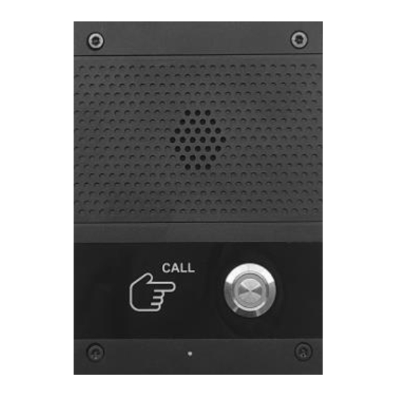
DP98 DP98V 2 Physical Specifications 88*120*35(mm) DP91 Device Dimension(L*W*H) 105*132*40(mm) DP92 Device Dimension(L*W*H) 105*175*40(mm) DP92V Device Dimension(L*W*H) 88*173*37(mm) DP98 Device Dimension(L*W*H) 88*173*37(mm) DP98V Device Dimension(L*W*H) - Page 5 2.1 Front Panel (Part of the models) DP91 DP92 DP92V DP98 DP98V...
- Page 6 2.2 DP9 Series Button HD Camera Door Access × × Single DTMF tones DP91-S × × Double DTMF tones DP91-D × × Single DTMF tones DP92-S × × Double DTMF tones DP92-D × √ Single DTMF tones DP92-SG × √...
- Page 7 2.3 Interface Description Name Description Ethernet interface: standard RJ45 interface, 10/100M adaptive, it is recommended to use five or five types of network cable 12V+, 12V- Power interface: 12V/1A input S1-IN, S-GND To connect indoor exit button or alarm input NC, NO, COM To connect door lock, alarm...
-
Page 8: Installation
2.4 Wiring Instructions DP9 series only supports an external power supply to connect the electronic lock. NO: Normal Open, idle status of the electric lock is opened COM: COM1 interface NC: Normal Closed, idle status of the electric lock is closed... -
Page 9: Obtaining The Device Ip Address
Electric impact drill with a 6mm drill bit 3.2 Steps(Take DP98V for example) (1)Drill four holes on the wall with a spacing of 60*60 mm for the frame installation, then insert a plastic expansion tube, and next use KA4*30 screws to tighten the back panel on the wall. - Page 10 5.2 Add the SIP account Configure the SIP account status, register name, username, password, and SIP server IP and port by assigning the SIP account on the server side respectively, and finally click the submit button. 5.3 Set Door Access Parameters Click "Equipment->Access"...
-
Page 11: Door Open Setting
6 Door Open Setting 6.1 Open Door by DTMF Code Click "Equipment->Access", select "Open Door by DTMF Code" to enable this function, and set the DTMF code for opening the door; When the intercom calls the indoor monitor, during the call, the indoor monitor can send DTMF code to open the door. - Page 12 Click "Equipment->Access", select "Access Card", swipe a new card to the intercom, then refresh the web GUI, RFID card number will be displayed on GUI automatically. then click "add"; The door can be opened successfully by swiping the card with the corresponding door card.
Need help?
Do you have a question about the DP9 Series and is the answer not in the manual?
Questions and answers