Advertisement
- 1 Before You Begin...
- 2 Chassis Specifications DG-87
- 3 Chassis Specifications DG-86
- 4 Chassis Specifications DG-85
- 5 Chassis Specifications DG-84
- 6 Parts Descriptions
- 7 Removing the Front Panel
- 8 Installing the Motherboard
- 9 Installing PCI-E Graphics Card (s)
- 10 Connecting Front Panel LED / USB / Audio / etc Headers
- 11 K-Boost Button Controls
- 12 Removable 3.5" / 2.5 "HDD cage (s)
- 13 Installing in the 3.5" 12.5" drive bay
- 14 2.5" only bay
- 15 Fan installation / Replacement
- 16 Documents / Resources
Before You Begin...
EVGA is reinventing the Full Tower case. The EVGA DG 8 Series is not just the large metal box of the past but now a focal point, with everything you would come to expect of the EVGA DG 8 Series, such as quality design, high end materials, premium finishes, and backed by EVGA's legendary customer service Made from Industrial grade SPCC Steel, ABS Plastic, with a metallic gunmetal grey coating and a Polycarbonate window (excluding DB-84), this is the perfect solution to both bui d your 4 Way SLI, water cooled, all solid state dream machine and be eye catching so you have to show it off! With the EVGA DG-8 Series you sacrifice NOTHING, designed for the best of the best hardware internal y, the only thing that changes in this line are the finishes. You can opt for the baseline which will still support all your 4 way SLI and watercooling needs in a more basic package, all the way up to a smoked acrylic side panel window to see all your hard work on the build, and still have a 7 inch integrated touchscreen, HDMI, USB and audio jacks to make the case natively VR ready.

Chassis Specifications DG-87

- Dimensions / Weight
(L x W x H): 686 x 270 x 642mm / 27 x 10 6 x 25 3"
Weight: 20 5kg / 45 21b - Expansion Slots
9
- Fans
3 Top, 3 Right, 2 Left
Includes 1 Top, 3 Right, 2 Left
Fan controler
Software and button controls - I \ O Ports
USB 2.0 crop)
USB 3.0 (Front)
USB Type C (Front)
HD Audio Out HD
Audio In
HDMI
K Boost
- Form Factor
EATX - Motherboard / Graphics Card Support
Supports mini-ITX through EATX motherboards
Supports most high performance graphics cards
Chassis Specifications DG-86

- Dimensions / Weight
(L x w x H): 686 x 270 x 642mm / 27 x 10 6 x 25 3"
Weight: 20 Ikg / 44 31b - Expansion Slots
9
- Fans
3 Top, 3 Right, 2 Left
Includes 2 Right, 2 Left
Fan Controller with Software based controls - I\O Ports
USB 2.0 (Top)
USB 3.0 (Front) USB
Type C (Front)
HD Audio Out
HD Audio In
HDMI
K Boost
- Form Factor
EATX - Motherboard / Graphics Card
Support Supports mini-TX through EATX motherboards
Supports most high performance graphics cards
Chassis Specifications DG-85

- Dimensions / Weight
(L x W x H): 686 x 270 x 642mm / 27 x 10.6 x 25 3"
Weight: 17 5kg / 38.51b - Expansion Slots
9
- Fans
3 Top, 3 Right, 2 Left - I\O Ports
USB 2.0 (Top)
USB 3.0 (Front)
HD Audio Out
HD Audio In
HDMI
K Boost
- Form Factor
EATX
- Motherboard / Graphics Card
Support Supports mini-TX through EATX motherboards
Supports most high performance graphics cards
Chassis Specifications DG-84

- Dimensions / Weight
(L x w x H): 686 x 270 x 642mm / 27 x 10.6 x 25 3"
Weight: 17 5kg / 38.51b - Expansion Slots
9
- Fans
3 Top, 3 Right, 2 Left - I\O Ports
USB 2 0 (Top)
USB 3 0 (Front)
HD Audio Out
HD Audio In
HDMI
K Boost
- Form Factor
EATX - Motherboard / Graphics Card Support
Supports mini-TX through EATX motherboards
Supports most high performance graphics cards
Parts Descriptions
The following accessories are included with the DG-8 Series Chassis:
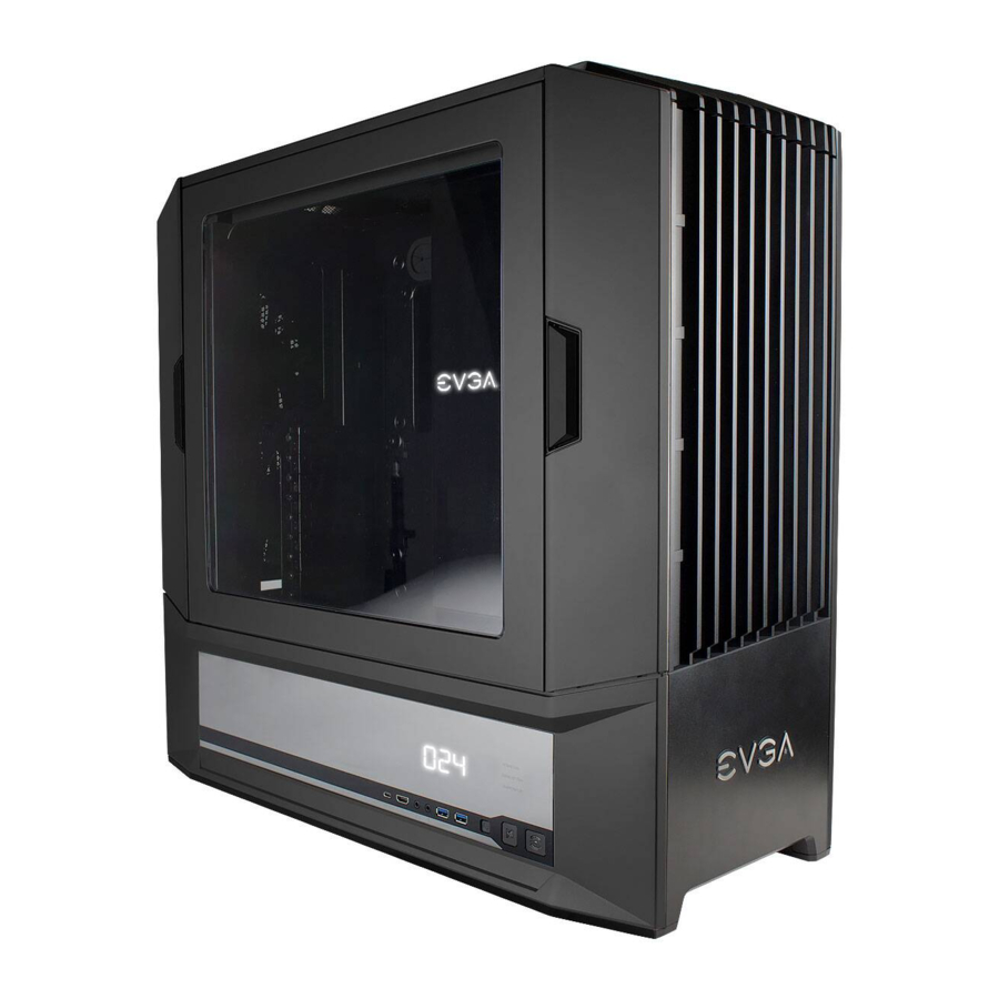
- EVGA DG-8 series Chassis
The EVGA DG full tower chassis.
![]()
- 24pcs PW Screw M3*0.5 L5
Fine thread bolt, used for various drives.
![]()
- 20pcs Flat Screw M3*5 L4
Short, flathead, fine thread screws for devices with limited clearances
![]()


- 45pcs PH Screw #6-32*4.8L
Standard coarse thread chassis bolts, used for standoffs, PSUs, and other devices
![]()

- 2pcs Screw, HEX Bolts #6-32*6.5L
Additional motherboard standoffs
![]()

- Manual
All the important information. You should know, you are reading it right now!
![]()

Removing the Front Panel

Press the button circled n red to open the door of the case
Push the hinge down, circled in red, down to remove the side panel
Installing the Motherboard
Install the 10 shield in the case before attempting to mount the board
Align the motherboard with the tray and make note of the standoffs use to ensure you have the board properly secured
Rest the motherboard on the standoffs, aligning the holes on the board with the standoffs; make sure you have the same number of standoffs showing through the holes that you counted before installing the motherboard. If you do NOT, then you have one aligned on the bottom of the board which WILL cause a ground fault, and possib y damage the board if you attempt to use it like this.
Once all of the standoffs are accounted for through the holes in the board, attach the board to the chassis with the provided screws
Tighten the screws. The board should now be properly aligned and mounted

Installing PCI-E Graphics Card (s)
Remove the screws over the card slots, and remove the slot cover(s) Align the bus connector on the card with the slot, and insert the card Any components that protrude from the devices mounting bracket should align with the slots at the back and be available for connection form the back of the case Align the hole in the top of the mounting bracket of the card previously inserted with the threaded hole that was holding the screw retaining the slot cover previously, and reinsert the screw, tightening it accordingly.
Connecting Front Panel LED / USB / Audio / etc Headers
Connect the Power LED and Power Switch cables. Make sure that the Power LED is in the correct + / orientation. Please consult your motherboard documentation on the proper ocation for connection

The USB 3 0 Internal Cable allows for full support of USB 3 0 devices, please consult your motherboard documentation to properly connect this

The USB 2 0 Internal Cable allows for full support of USB 2.0 devices, please consult your motherboard documentation to properly connect this.

The HD audio connector supports HD Audio, p ease consult your motherboard documentation on the proper ocation of connection

A VR edition card can connect to the internal HDMI header on your graphics card to the HDMI out case header.

The bundled fans connect to standard 3pin fan headers on your control hub in the case which supports 6 3pin fans

Connect the 4 pin Molex to power the fan controller

If you want to use the included case lighting, please attach a SATA power cable to the front panel as well.

Included Thermal probe will show ambient case temps

All of the above are attached to this front panel device.

Fan controller operated between 5v 12v. However if you use a fan that requires less than 5v to function and the controller is set to its lowest setting, the fan will NOT spin. Fan headers are rated for a max current of 1 (one) amp / 12 Watts per header. **DO NOT ATTACH PUMPS TO THESE HEADERS**
Included fans have a default setup speed of 50% for intake and exhaust. The fans are increased by 5% with a press of the up button, and will go to 100% if that button is held
Pressing the down button will reduce the fan speed by 5%, holding the down button will turn the fans off.
Press "Mode" to togg e between intake / exhaust fan speed, and case temp
K-Boost Button Controls
Pressing the K-Boost button will activate the feature
With an Nvidia GPU, it will go into K Boost mode, where it is locked at Boost Clock, the CPU will go into High Performance mode, and the fans will go to 100%
With a non Nvidia GPU the CPU will still go into performance mode and the fans go to 100%
Pressing K-Boost a second time will disable the function
Returns all applicable components to a normal state, and fans reduced to 50%
K-Boost fan speed range can be set. Press the K-Boost button and set the desired fanspeed and it will be saved into the firmware
LED will display case temp
Press and hold the "mode" button will reset all values to default
Removable 3.5" / 2.5 "HDD cage (s)
These will mount in various places in your DG-8 series case
Held to the case by sliding the edges under alignment tabs, then screwing down the opposite edge
Bolt in a 3 5 or 2 5" SSD/HDD
Make sure power and data cables are connected before powering on

Installing in the 3.5" 12.5" drive bay
Remove the drive tray form the pull-out rack. The removable tray can support either 3 5" or 2 5" HDD's and SSD's Place the desired drive into the tray and attach with the screws included with your drive
Slide the drive tray back into the rack, and ensure the power and data cable are connected on the back

2.5" only bay
This is a mounting bracket for a single 2 5" drive, these are mounted on the back of the motherboard tray. Place the drive on the bracket and attach using the screws that came with the drive
Slide the bracket onto the alignment tabs on the case, and then screw it down on the opposite side
Ensure the power and data cables are attached before powering on
Also keep in mind that the HDD/SSD mounts, due to the size of this case, are nearly 700mm away from the SATA ports on a standard motherboard. SATA cables onger than the standard 400mm will be necessary

Fan installation / Replacement
There is a maximum of 8 fans mounted to the case, 3 in front, 3 on top, and 2 at the rear, designed to create cross-flow ventilation

All fans are attached with Self Tapping Screws

Front fans are for intake, top are for exhaust, the rear can either be exhaust for the wind tunnel design, or intake to force all hot air through maintaining positive air pressure in the case.

Press the button on the right side, then you can remove the cover, from there pull out filter.
For top cover, pul up and the top cover will come off, from there you can remove and clean the dust filter.
For the PSU filter, it can be slid out direct y with no additional disassembly required

Documents / ResourcesDownload manual
Here you can download full pdf version of manual, it may contain additional safety instructions, warranty information, FCC rules, etc.
Advertisement


Need help?
Do you have a question about the DG-8 and is the answer not in the manual?
Questions and answers