Advertisement
- 1 Before You Begin...
- 2 Chassis Specifications DG-7
- 3 Parts Descriptions
- 4 Removing the Front Panel
- 5 Installing the Motherboard
- 6 Installing PCI-E Graphics Card(s)
- 7 Connecting Front Panel LED/USB / Audio / etc Headers
- 8 KBoost Button Controls
- 9 Removable 3.5" / 2.5"HDD Brackets
- 10 Fan Installation / replacing
- 11 DG-76 / 77 RGB LED Control Board
- 12 Installing RGB LED Fans to Control Board
- 13 RGB and K-Boost Button Controls
- 14 Documents / Resources
Before You Begin...
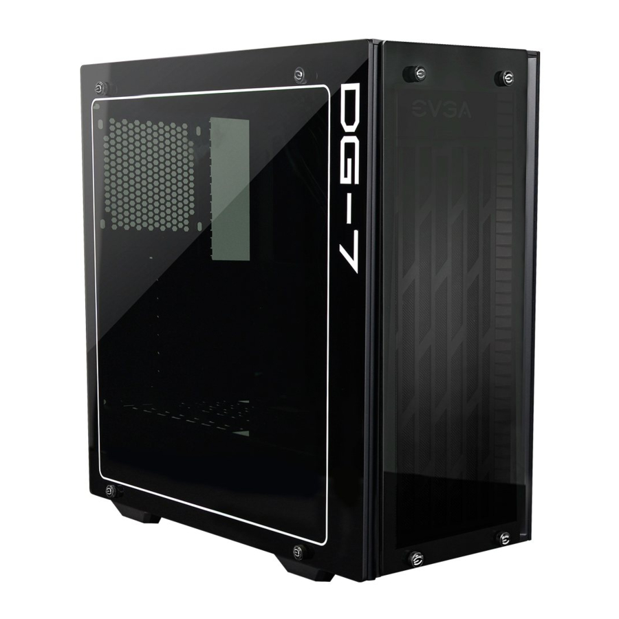
PC gamers are so over the modern Mid-Tower case. Welcome to the future of the Mid-Tower case, the EVGA DG-7 Series. The DG-7 is not another beige or light grey box that belongs back in the 1990s; instead, EVGA has designed the case you deserve to give it the fit and finish that matches and exceeds the practicality of the tried and true PC standard.
The DG-7 Series has nothing to hide and proves it by using Tempered glass side panels*, leaving you with an unobscured view of your system's hardware. With the EVGA DG-7 Series you sacrifice NOTHING. Its sleek design leaves you with plenty of desk space, and the black framing and smoked tempered glass gives it an undeniably slick profile. The DG-7 has support for mlTX, mATX, and ATX motherboards; SLI; mounts for a radiator up to 120mmx360mmx60mm; rounds out the design with Power / Reset buttons, K-BOOST@* USB 3.0, and audio jacks to make the case most impressive.
*On select models.

Chassis Specifications DG-7
- Dimensions / Weight
DG-73 (LxWx H): 472 x 204 x 477mm 18.58 x x 18.78"
DG-75 (LxWx H): 470 x 211 x 477mm 18.5 x 8.30 x 18.78"
DG-76 / 77 (LxVVx H): 483 x 211 x 477mm 19.01 x 8.30 x 18.78"
DG-73 Weight: 8.0 Kg / 17.63 lb
DG-75 Weight: 8.86 Kg / 19.53 lb
DG-76 Weight: 9.15 Kg / 20.17 lb
DG-77 Weight: 10.05 Kg / 22.35 lb - Expansion Slots
7 - Fans
3 x 120 or 2 x 140 Top, 3 x 120 or 2 x 140 right, 1 x 120 left.
Top and right fan mount points accommodate 140mm and / or 120mm
Includes (varies by model)
DG-73 and 75: O top, 1 right, 1 left
DG-76: O top, 2 right, 1 left
DG-77: 1 top, 2 right, 1 left
All included fans are 120mm. - TOP I\O
USB 3.0
HD Audio Out
HD Audio In
Power Button
Reset Button
K-BOOST@ button* *Availableon DG-77 only - Case Form Factor
ATX - Motherboard / Graphics Card Support
Supports mini-ITX, micro-ATX, and ATX motherboards
Supports most high performance graphics cards
Parts Descriptions
The following accessories are included with the DG-7 Series Chassis:
- EVGA DG-7 series Chassis
The EVGA DG-7 series Mid-Tower chassis.
![]()
- 27pcs #6-32 5L
Fasteners for holdingMothaboad to standoffs, and 3.5 HDD.
![]()


- 28pcs KB5x 10L
Self tapping screws for fans.
![]()
- Colored decal set
Colored decals for the EVGA logo on the front panel of DG-7.
![]()


- 13pcs Standoff 6-32 female end
Standoff screws for the motherboard. Use with #6-32 5L screws to fasten the motherboard to the DG-7.
![]()
- 16pcs M3 L4
Fasteners for SSD's.
![]()
- Manual
Installation and setup information you are currently reading.
![]()
- Textured Thumbscrews
Thumb screws that hold the case panels on. Center has an AIGA logo but can be covered with included stickers to change the look of the screw.
![]()


Removing the Front Panel
The front panel is not hinged. There are 4 thumb screws in the corners, remove those and the side panel will come off.

Installing the Motherboard
Install the 10 shield in the case before attempting to mount the board.
Align the motherboard with the tray and make note of which standoff holes are needed for your specific motherboard.
Thread the standoffs into the holes and keep count of how many you use. Depending on the motherboard, you will need between 5 and 10 standoffs. Keep in mind that the DG-7 has some permanent standoffs, as well.
Rest the motherboard on the standoffs, aligning the holes on the board with the standoffs; make sure you have the same number of standoffs showing through the holes that you counted before installing the motherboard. If you do NOT, then you have one aligned on the bottom of the board which WILL cause a ground fault, and possibly damage the board if you attempt to use it like this.
Once all of the standoffs are accounted for through the holes in the board, attach the board to the chassis with the provided screws.
Tighten the screws. The board should now be properly aligned and mounted.

Installing PCI-E Graphics Card(s)
Remove the screws over the card slots, and remove the slot cover(s). Align the bus connector on the card with the slot, and insert the card. Any components that protrude from the device's mounting bracket should align with the slots at the back and be available for connection from the back of the case. Align the mounting bracket holes on your graphics card with the threaded holes in the DG-7's card slot bracket. Fasten the graphics card to the bracket by using the screws obtained when removing the card slot covers. Make sure that your graphics card is installed perpendicular to the motherboard and the display outputs are centered between the card slots; otherwise, the motherboard may suffer a ground fault from a graphics card if the HDMI/DP connectors touch the metal alignment pieces between slots.
Connecting Front Panel LED/USB / Audio / etc Headers

Connect the Power LED and Power Switch cables. Make sure that the Power LED is in the correct + / - orientation. Please consult your motherboard documentation on the proper location for connection.

The USB 3.0 Internal Cable allows for full support of USB 3.0 devices, please consult your motherboard documentation to properly connect this.

The HD audio connector supports HD Audio, please consult your motherboard documentation on the proper location of connection.

If you want to use the included case lighting, please attach a SATA power cable to the top panel as well.

KBoost Button Controls
Pressing the KBoost button will activate the feature
When KBoost mode is enabled, a NVIDIA GPU will become locked at Boost Clock*. Please note that the software will notify you if certain programs need to close in order to enable / disable KBoost Mode.
When KBoost is enabled, your CPU will go into performance mode*, regardless of whether you are using a NVIDIA card or not.
Pressing KBoost a second time will disable the function*
Returns all applicable components to a normal state*
*Please see details and configuration options of the KBoost button
Removable 3.5" / 2.5"HDD Brackets
These will mount in various places in your DG-7 series case.
Unscrew the mount and slide the bracket out of the alignment slots.
Place the storage device onto the bracket, and use the included screws to attach the storage device to the bracket.
Slide the bracket back into the alignment slots, and ensure it is bolted into place.
Make sure power and data cables are connected before powering on.
2.5" SSD, and 3.5" HDD's are installed the same way, just to their specific sized brackets.

Fan Installation / replacing


There is a maximum of 7 fans mounted to the case, 3 (2 tfusing 140mm fans) in right, 3 (2 if using 140mm fans) on top, and 1 at the left, designed to create cross-flow ventilation. All fans are attached with Self Tapping Screws.
Front / Right fans are for intake, Top fans are for exhaust, and the Rear / Left fans can be used either for exhaust as part of a wind-tunnel design or for intake to create additional positive air pressure and force the exhaust out the Top.
The Front / Right panel must first be removed to remove the Top panel.
Remove the 4 thumb screws holding the Front / Right cover to remove the panel. Remember to remove the fan grill behind the cover, and disconnect any cables attached to the RGB Control Board.
Once the Front / Right components are removed, lift the Top grill and RGB Control Board straight up and out.
The PSU dust filter is located at the bottom of the case and accessible from the outside. The PSU filter can be slid out with no disassembly required.

DG-76 / 77 RGB LED Control Board
The DG-76 and DG-77 cases feature a control board used to control the lighting for RGB LED fans. The control board is located inside, near the top-right of the case. This control board features headers for up to six (6) RGB fans. Please make sure to provide power to the control board by connecting a SATA power cable from your power supply to the control board. You will not be able to control the lighting through the DG-7 if power is not connected. Connected fans can be controlled through the DG-Tuner software, shown below.

Installing RGB LED Fans to Control Board
Please note that RGB LED fans use a type of connector that must be correctly installed for the lighting to be properly controlled. Failure to install your cable properly will prevent the fan lighting from working or being controlled. To install a RGB LED fan, make sure that the arrow on the RGB connector lines up with the 12V pin on the RGB header on the control board, as shown in the image. This will ensure that the RGB fan is properly connected and detected by the DG-Tuner software for the DG-76 and DG-77 cases.

RGB and K-Boost Button Controls
The DG-77 case supports the EVGA KBoost function, and DG-76 and DG-77 both support RGB LED controls through DG Tuner software. The KBoost function can also be enabled / disabled from the button on the case. To use the RGB I FD and/or KBoost functions, make sure to plug the DG-7's USB 2.0 header into the 9pin USB 2.0 header on the motherboard. Once the USB 2.0 is connected to the case, boot into Windows and install the DG-7 Software suite.

When the software is launched, you will see the software title at the top; a settings button on the right; the reset button to the left; and the LED controls, KBoost button, and the HW Monitor on the bottom. KBoost will ramp up the CPU to its peak clock set in BIOS by EIST and / or any overclock set in the BIOS; all NVIDIA-based GPUs supporting GPU Boost 2.0 or higher will ramp up to their current max boost clock. Clicking on the LED icons will bring you to the menu on the right. This menu will allow you to sync all LEDs based on the LED pattern you select, or you may click each individual LED and configure them separately. The On / Off controls allow you to select the color seen when "ON". "Rainbow" will cycle the LED colors, and "Breathing" will slowly brighten and darken the LED based on the color you choose.

The reset button, when pushed will return all configurations and settings within this software to their factory defaults.

Start with Windows allows the DG-7 software to auto start when the system is booted, and the next option will determine whether the DG-7 software will start on screen or minimized to the task bar.
Check update will give you the following options Never, On Startup, On Startup Daily, On Startup Weekly, or On Startup Monthly, to select how often the DG-7 software will check with EVGA.com for updates.
KBoost ON and OFF both have the same options, and based on the Windows power options. Both On and Off share the same options of "High Performance", "Balanced", and "Power Saver".
www.evga.com
Documents / ResourcesDownload manual
Here you can download full pdf version of manual, it may contain additional safety instructions, warranty information, FCC rules, etc.
Advertisement


Need help?
Do you have a question about the DG-7 and is the answer not in the manual?
Questions and answers