EcoFlow POWEROCEAN Installation Manual
Home solar battery solution
Hide thumbs
Also See for POWEROCEAN:
- Quick installation manual (3 pages) ,
- Installation manual (34 pages)
Table of Contents
Advertisement
Quick Links
INSTALLATION GUIDE
V1.2
ECOFLOW POWEROCEAN
Home Solar Bat ter y Solution
For the latest documents, please scan the QR code or visit:
https://enterprise.ecoflow.com/eu/documentation
IMPORTANT
• Before installing, operating, and maintaining the equipment, read and
follow up Installation Guide and Safety Instructions.
Advertisement
Table of Contents

Related Manuals for EcoFlow POWEROCEAN


Summary of Contents for EcoFlow POWEROCEAN
- Page 1 INSTALLATION GUIDE V1.2 ECOFLOW POWEROCEAN Home Solar Bat ter y Solution For the latest documents, please scan the QR code or visit: https://enterprise.ecoflow.com/eu/documentation IMPORTANT • Before installing, operating, and maintaining the equipment, read and follow up Installation Guide and Safety Instructions.
-
Page 2: Table Of Contents
CONTENTS Safety Instructions Preparing Tools and Instruments What's In The Box System Installation Installation Environment Requirements Installation Space Requirements Installing Battery Installing Inverter System Overview Electrical Connection Connecting PE Cables Connecting PV Input Cables Connecting GRID Cables Connecting BACKUP Cables Connecting Battery Power Cables Connecting Battery Communication Cables Connecting Communication Connector... -
Page 3: Safety Instructions
• Before installing, operating, and maintaining the equipment, read and follow up Installation Guide and Safety Instructions. • Personnel who plan to install or maintain EcoFlow equipment must receive thorough training, understand all necessary safety precautions, and be able to correctly perform all operations. -
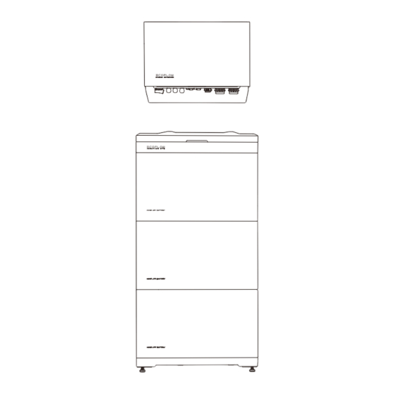
Page 4: Preparing Tools And Instruments
• After unpacking, check that the deliverables are intact and complete. If any item is missing or damaged, contact the supplier. • It is recommended to keep the original package for further needs. ·ECOFLOW POWEROCEAN HYBRID INVERTER BOX ×1 ×1 ×1... - Page 5 Disassembly and OT terminal Tubular Terminal (For wire gauge 26AWG/0.25mm²) (For wire gauge 22AWG/0.5mm²) (For wire gauge 18AWG/1mm²) Assembly Tool (For wire gauge 10AWG/6mm²) ·ECOFLOW POWEROCEAN LFP BATTERY BOX ×1 ×2 Battery T-shaped mounting piece(M6) Battery L-shaped mounting piece ×8 ×2...
-
Page 6: System Installation
System Installation WARNING Installation Environment • The installation and use environment must meet relevant international, national, and local standards for lithium batteries, and are in accordance with the local laws and regulations. Requirements NOTICE • When installing the equipment in a garage, keep it away from the drive way. •... -
Page 7: Installing Battery
DANGER Installing • When drilling holes, avoid the water pipes and power cables buried in the wall and under the floor. Battery • When drilling holes, protect the battery base from shavings or dust. • Before installing the battery, make sure that the click-on terminals on the top and bottom of the battery are free of foreign objects or any liquid. - Page 8 ×2 ×1 ×2 ×2 5.0N·m 10mm ❷ ❷ 2.5N·m ❶ 5.0N·m ❸ ❶ *Fully tighten it to secure. ❶ ❷ ×1 ❶ 5.0N·m ❶ ❷...
-
Page 9: Installing Inverter
NOTICE Installing • Mount the inverter vertically or tilted back (<30°) to facilitate the heat dissipation of the inverter. Inverter ×1 ×4 ×1 ×2 (M6*60) A1 0 Torque socket (10mm) ❷ 5.0N·m (Ф7mm) The anti-theft lock is prepared by the customer if needed. - Page 10 • All electrical connections must be carried out by a professionally trained and certified electrician. Connection NOTICE • Please purchase cables that meet local certification standards. - EcoFlow PowerOcean Hybrid Inverter - (Optional) 4G module • For network • Sold separately...
-
Page 11: Connecting Pe Cables
Connecting NOTICE PE Cables • Ensure that the PE cable is connected securely. ×3 Cable Cable core GRID terminal L3 N PE OT terminal Crimping tool PE-busbar DANGER Connecting • Before connecting the PV input cables, ensure AC switch connected to the inverter and the PV SWITCH on the inverter are OFF. -
Page 12: Connecting Grid Cables
×1 8-10mm ❶ ❷ 8-10mm Ensure that the cable cannot be pulled out after being crimped. Ensure that the cable Remove Protective cap. polarities are correct. PV1+ PV1+ PV1- PV1- Click Set the multimeter to DC gear to measure the voltage at the DC position. If the voltage is a negative value, the PV input polarity is incorrect and needs correction. -
Page 13: Connecting Backup Cables
FIVE-CORE WIRE (L1, L2, L3, N, PE) ×1 GRID Terminal GRID Terminal L3 N Remove protective cap GRID Connector CAUTION • Before installing, operating, and maintaining the equipment, always disconnect it from all power. Connecting • Do not connect the BACKUP connector to the GRID terminal of the inverter. BACKUP Cables •... -
Page 14: Connecting Battery Power Cables
DANGER • Before disconnecting the Battery terminals, you MUST set the BATTERY SWITCH on top of the Junction Connecting Box to OFF position, then press and hold the BATTERY ON/OFF button on the right side of the junction Battery Power Cables box for 10 seconds, until the indicator is off. -
Page 15: Connecting Communication Connector
- OPTIONAL ×2 NOTICE Connecting • COM terminal supports logic interface connection. Logic interface is required by some local regulations that can be operated by a simple switch or contactor. Communication Connector • When the switch is closed, the inverter can operate normally.When the switch is opened, the inverter will reduce its active power to zero within 5s. - Page 16 ×1 ❶ Remove protective ❷ D:4-8mm Click D:8-11mm -(OPTIONAL) INSTALLING EPO NOTICE • Before installing EPO, please remove the shorting wire between PIN14 and PIN16. ×1 D:4-8mm D:8-11mm ❶ Remove protective cap ❷ Click 14 |...
-
Page 17: Connecting Smart Meter
NOTICE Connecting • It is recommend to use of CAT5 or higher network cable. • Please use the smart meter included in the box. Smart Meter ADL400N-CT/D10 METER INSTALLATION CONNECTING SMART POWER SENSOR METER VOLTAGE SAMPLING COMMUNICATION CABLE Refer to line 2 below, terminal 1, 2, and 3 are wired to phase a, b, and c, Assembly crystal terminal in accordance with respectively, to complete the voltage sampling. -
Page 18: Connecting To Notice Internet
YDS60-80 METER INSTALLATION Grid a-phase voltage sampling Output METER SAMPLING Grid b-phase voltage sampling Output Find the home main road and connect the smart Grid c-phase voltage sampling Output meter as shown in the diagram. Neutral pole of sampling Output METER COMMUNICATION Inverter communication port Find communication port A,B on the meter... - Page 19 Both ends of the network cable use the T568B wiring standard. ×1 T568B T568B 10-20 mm 10-20 mm Test network cable connection. If the LEDs of the two RJ45 ports light up in sequence, it indicates that the network cable is correctly wired and should be fully operational.
-
Page 20: Checking Before Power-On
EPO shutdown / Fault, system cannot work Switch All the switches connecting to the system are OFF. ECOFLOW POWEROCEAN BATTERY JUNCTION BOX The AC/DC power cable, battery cable, and Cable connection communication cable are connected correctly, securely, Charge Status Description and reliably. -
Page 21: System Commissioning
Wifi, then click "Join". https: //download.ecoflow.com/ecoflowproapp 3. After successfully connected your phone to "PowerOcean_ xxxx", tap the "EcoFlow Pro" on the top left of your EcoFlow Pro phone's Wi-Fi setting page to shift back and proceed to commissioning. - Page 22 COMMISSIONING After bound device successfully, the device enters the three-step commissioning process. Step1: Internet Setup click Internet Setup to start the network configuration. a. Wi-Fi Click WiFi,select the appropriate WiFi name and enter the password and click continue. b. Ethernet Connect the system to a router using a network cable, wait a minute before proceeding.
- Page 23 (Optional) Update firmware before carrying out Device Setting. If there is a firmware update available for the EcoFlow PowerOcean system, the update page will pop up to notify you when proceeding this step. The "Skip"...
-
Page 24: How Users Add Devices
Scan the QR code or download at: https://download.ecoflow.com/app • After manually adding device EcoFlow PowerOcean EcoFlow App using the EcoFlow User App, users scan the home owner access QR code to bind it. 2. CREATE NEW ACCOUNT AND LOG IN. 3. ADD DEVICE MANUALLY. - Page 26 Raccolta carta...
Need help?
Do you have a question about the POWEROCEAN and is the answer not in the manual?
Questions and answers