Advertisement
Quick Links
Advertisement

Subscribe to Our Youtube Channel
Related Manuals for Thermal Gas Systems HALOGUARD IR


Summary of Contents for Thermal Gas Systems HALOGUARD IR
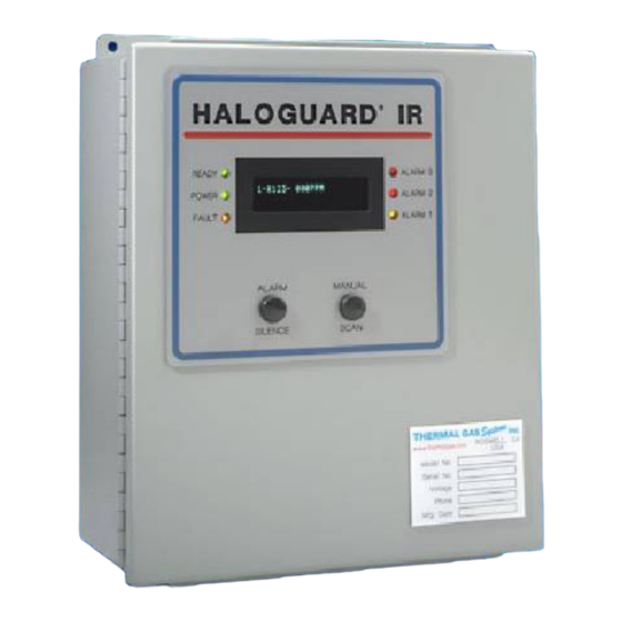
- Page 1 HALOGUARD IR MONITOR INSTRUCTIONS FOR ADDING AND REPLACING OXYGEN SENSORS (Procedures also apply to Haloguard III Monitors 11285 Elkins Road Bldg. H-1 Roswell, GA 30076 TEL: 770-667-3865 FAX: 770-667-3857 www.thermalgas.com 06024 Rev. 0 H3 O2 Sensor Replacement.DOC...
-
Page 2: Before Installation
2. Remove cover from Haloguard IR Controller using Phillips screwdriver. Remove “AUDIBLE” Jumper (See FIGURE 1 - Haloguard IR Printed Circuit Board for location) Refer to FIGURE 1 and 2 before proceeding. DO NOT CUT SUPPLIED CABLE 06024 Rev. 0... - Page 3 4b below.) Attach supplied 18” cable with DIN Connector to EXT INPUT 1, 2, or 3 terminal block (See Figure 1 - Haloguard IR Printed Circuit Board above for location) on the Haloguard IR circuit board.
-
Page 4: External Input
the Haloguard IR circuit board. (See Figure 1 - Haloguard IR Printed Circuit Board for location) Connect extended sensor cable to terminal block. (See FIGURE 2 for terminal connections) Splice or solder 18” cable to end of extension cable. -
Page 5: Troubleshooting
2. Description of problem. 3. Remove cover from the controller. Place Setup Jumper on Alarm setting and record settings. 4. Using FIGURE 1 - Haloguard IR Printed Circuit Board as a guide, measure voltage between SIG and GND. Write down values.
Need help?
Do you have a question about the HALOGUARD IR and is the answer not in the manual?
Questions and answers