Table of Contents
Advertisement
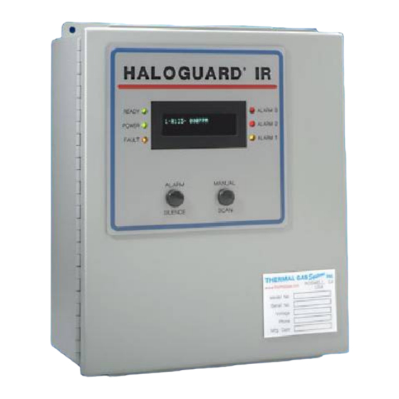
MULTI-POINT, COMPOUND SPECIFIC MONITOR
S E R IA L N O .
M O D E L N O .
T em p . R an ge
1 - = > 60
2 - = 40 - 60
3 - = < 40
Rev.1/26/01
HALOGUARD
INSTRUCTION MANUAL
o
F
o
F
o
F
G as T yp e
1 - R -11
2 - R -12
R ang e
3 - R -22
1-0-1000ppm
4 - R -134 a
5 - R -113
6 - N H 3
7 - R -123
11285 Elkins Road Bldg. H-1
Roswell, GA 30076
TEL: 770-667-3865
FAX: 770-667-3857
www.thermalgas.com
TM
IR
O u tp uts
1 - 4 x 5A R elays
2 - 0 – 5/10 V D C
3 - 4 - 20m A
4 - R S 232/485
5 – 7 x 10A.
O ptions/A ccessories
A - Audible Alarm
B – B attery B /U -U P S
E - In let/O utlet E xtension
L - Strobe Light
S - S canner
R – R em ote E xpan sion
M odu le
1
Advertisement
Table of Contents

Related Manuals for Thermal Gas Systems HALOGUARD IR


Summary of Contents for Thermal Gas Systems HALOGUARD IR
-
Page 1: Instruction Manual
HALOGUARD MULTI-POINT, COMPOUND SPECIFIC MONITOR INSTRUCTION MANUAL S E R IA L N O . M O D E L N O . T em p . R an ge 1 - = > 60 O u tp uts 2 - = 40 - 60 1 - 4 x 5A R elays 3 - = <... -
Page 2: Table Of Contents
1. Typical Area Monitoring Installation ----------------------------------------- 3 2. Mounting Dimensions ------------------------------------------------------------ 4 3. LCD Display Information -------------------------------------------------------- 4 4. Haloguard IR ----------------------------------------------------------------------- 5 5. Analog Jumper Settings ---------------------------------------------------------- 6 6. Circuit Board ----------------------------------------------------------------------- 7 7. Setup & Configuration Jumper Settings---------------------------------------- 8 8. -
Page 3: Unpacking Instructions
Contact us for specific gas interference. 3. The Haloguard IR should be installed indoors, about five feet above the floor and at a location easily visible to operators, in an area with minimal vibration, and with temperature and humidity changes like sample pick-up location. -
Page 4: Function Of Led's, Pushbuttons, & Lcd Information
Reset is automatically initiated on start-up and after power failure. 7. Optional Display Features: TWA Integration – Haloguard IR calculates an 8 hr. Time Weighted Average (TLV-TWA), displays this value on LCD, activates Alarm 1 LED and relay if factory set PPM value is exceeded. -
Page 5: Haloguard Ir
Local Audible alarm-Opt. Outlet Analog/ Digital Output Relay/Binary Output Remote Power In 4-20mA, 0-5VDC 4x5A. dry contact Std Reset In 120/230Vac RS 232/485 serial Opt. 7x10A. dry contact Opt. 50/60Hz Aux. Inputs and Remote Expansion Module In Fig. 4-Haloguard IR Rev.1/26/01... -
Page 6: Installation
INSTALLATION 1. Check power supply and determine best location. (See Section “Before Installation”) 2. Disconnect power before beginning. Refer to figures 2, 3, 4, 5 and 6 before proceeding. 3. Installation a. Mounting Haloguard 1. Securely mount the unit to a wall or support using the (4) mounting holes. 2. -
Page 7: Circuit Board
6. Uninterruptable Power Supply (Optional) – Make sure UPS is fully charged. Plug UPS into power supply, turn switch ON. Connect Haloguard IR to UPS, with power cord provided c. On power-up, RESET and 20 minute count down will appear on LCD. For 20 minutes after power up all alarms and relays are automatically disabled. -
Page 8: Set-Up & System Configuration
SETUP and SYSTEM CONFIGURATION Locate configuration jumpers on Figure 6. Select configuration settings from the following: FUNCTION Select run for normal operation Set gas type and number of active channels SETUP TEST Sequentially activates all alarm & Fault LED’s & relays ALARM Set Point Adjustment for Alarm 1, 2, and 3 Zero Calibration... -
Page 9: Remote Expansion Module Terminations
5. Installation of Optional Remote IR Expansion Module Refer to FIGURE 4, 6, 8, and 9 before proceeding. DO NOT CUT SUPPLIED CABLE Controller is provided with 18” cable with DIN connector and expansion module is provided with 6-1/2’ cable. If cable extension is required we recommend 3 conductor 18 ga. cable with foil shield, Carol C2535 or equal. -
Page 10: Calibration, Testing, & Trouble Shooting
(See “Before Installation). and relocate sample point.. Keep in mind that the Haloguard IR is much more sensitive than hand held leak detectors, it may detect a leak when hand held units show no response ... -
Page 11: Maintenance & Specifications
Self-diagnostics will indicate the cause of any unusual malfunction. To obtain spare or replacement parts please contact Thermal Gas Systems, Inc. Part No.
Need help?
Do you have a question about the HALOGUARD IR and is the answer not in the manual?
Questions and answers