Table of Contents
Advertisement
sensoCOMFORT Boiler Schematics
and Installation Guide
Controls: sensoCOMFORT, VR 92(f), VR71, VR70, VR 66/2
This guide booklet contains information to assist in the installation and commissioning of your boiler
system. This booklet should be used alongside all the relevant manuals for the equipment supplied.
Please read the contents very carefully for a successful installation.
Table of Contents
General Notes .................................................................................................................................................. 2
Terms and Conditions for Vaillant Schematic Diagrams ................................................................................... 2
Schematic Diagrams......................................................................................................................................... 3
sensoCOMFORT Commissioning / Configuration ........................................................................................... 26
sensoCOMFORT System Configuration Relevant Settings .............................................................................. 30
Schematics Legend......................................................................................................................................... 37
Advertisement
Table of Contents

Related Manuals for Vaillant sensoCOMFORT


Summary of Contents for Vaillant sensoCOMFORT
-
Page 1: Table Of Contents
Boiler Schematics and Installation Guide Controls: sensoCOMFORT, VR 92(f), VR71, VR70, VR 66/2 This guide booklet contains information to assist in the installation and commissioning of your boiler system. This booklet should be used alongside all the relevant manuals for the equipment supplied. -
Page 2: General Notes
In no circumstances shall Vaillant be liable to you or any other third parties for any loss or damage (including, without limitation, damage for loss of business or loss of profits) arising directly or indirectly from your use of or inability to use, this diagram. -
Page 3: Schematic Diagrams
30. Care must be taken going through each setting diligently and adjust as necessary in accordance to system configuration and property requirements. Only key settings are listed in this document, refer to the sensoCOMFORT installation manual for further guidance. - Page 4 Combination Boiler, 1 Radiator Zone Schematic No. 20010-1001. See Page 34 for system configuration settings.
- Page 6 Combination Boiler, 2 Radiator Zones (Direct) Schematic No. 20021-1002. See Page 34 for system configuration settings.
- Page 8 Combination Boiler, 3 Radiator Zones (Mixed) Schematic No. 20030-1003. See Page 35 for system configuration settings.
- Page 10 Combination Boiler, 1 Radiator (Direct), 1 Underfloor (3 Party) Schematic No. 20022-1002. See Page 35 for system configuration settings.
- Page 12 Combination Boiler, 1 Underfloor (Mixed), 2 Radiator (Mixed) Schematic No. 20110-1003. See Page 36 for system configuration settings.
- Page 14 System Boiler, Domestic Hot Water, 1 Radiator Zone Schematic No. 10010-1011. See Page 30 for system configuration settings.
- Page 16 System Boiler, Domestic Hot Water, 2 Radiator Zones (Mixed) Schematic No. 10020-1012. See Page 30 for system configuration settings.
- Page 18 System Boiler (Exclusive), Domestic Hot Water, 3 Radiator Zones (Mixed) Schematic No. 10041-1013. See Page 31 for system configuration settings.
- Page 20 System Boiler (Exclusive), Domestic Hot Water, 1 Underfloor (Mixed), 1 Radiator (Mixed) Schematic No. 10030-1012. See Page 31 for system configuration settings.
- Page 22 System Boiler, Domestic Hot Water, 2 Radiator Zones, 1 Underfloor Zone (3 Party) Schematic No. 10060-1013. See Page 32 for system configuration settings.
- Page 24 System Boiler, Domestic Hot Water, 5 Radiator Zones (Mixed) Schematic No. 10100-1015. See Page 33 for system configuration settings.
-
Page 26: Sensocomfort Commissioning / Configuration
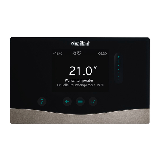
Commissioning / Configuration When the sensoCOMFORT is powered up for the first time, the installation assistance will guide you through several basic settings. Installation Assistant Use the scroll bar to the right of the screen to scroll through tick... - Page 27 Ensure you have completed the installation assistant on ALL other eBUS appliances / components before continuing with the installation assistant on the sensoCOMFORT. Tap on the tick to continue with eBUS system scan. Wait for the system scan to complete.
- Page 28 / components and restart the installation assistant of sensoCOMFORT. If this screen is displayed, take note of the required sensors and actuators and ensure they are connected.
- Page 29 Scroll down until “System configuration” is highlighted then press the tick. For the relevant system configuration settings in the sensoCOMFORT, refer to page 30; arranged by the schematic number in numerical order. Care must be taken going through each setting diligently and adjust as necessary in accordance to system configuration and property requirements.
-
Page 30: Sensocomfort System Configuration Relevant Settings
System Configuration Relevant Settings 10010-1011 - System Boiler, Domestic Hot Water, 1 Radiator Zone 10020-1012 - System Boiler, Domestic Hot Water, 2 Radiator Zones (Mixed) - Page 31 10030-1012 - System Boiler (Exclusive), Domestic Hot Water, 1 Underfloor (Mixed), 1 Radiator (Mixed) 10041-1013 - System Boiler (Exclusive), Domestic Hot Water, 3 Radiator Zones (Mixed)
- Page 32 10060-1013 - System Boiler, Domestic Hot Water, 2 Radiator Zones, 1 Underfloor Zone (3 Party)
- Page 33 10100-1015 - System Boiler, Domestic Hot Water, 5 Radiator Zones (Mixed)
-
Page 34: 20010-1001 Combination Boiler, 1 Radiator Zone
20010-1001 - Combination Boiler, 1 Radiator Zone 20021-1002 - Combination Boiler, 2 Radiator Zones (Direct) -
Page 35: 20030-1003 Combination Boiler, 3 Radiator Zones (Mixed)
20022-1002 - Combination Boiler, 1 Radiator (Direct), 1 Underfloor (3 Party) 20030-1003 - Combination Boiler, 3 Radiator Zones (Mixed) -
Page 36: 20110-1003 Combination Boiler, 1 Underfloor (Mixed), 2 Radiator (Mixed)
20110-1003 - Combination Boiler, 1 Underfloor (Mixed), 2 Radiator (Mixed) -
Page 37: Schematics Legend
Schematics Legend Boiler sensoCOMFORT Secondary Circulation Pump VR92 Primary Flow Pump Wiring Centre - VR 70 uniSTOR DHW Cylinder Wiring Centre - VR 71 VDM Pump Group Wiring Centre - VR 66 Distribution Bar High Limit Cut Out Zone Valve... - Page 38 Sales Enquiries Technical Enquiries For technical assistance: For installers wishing to purchase Telephone: 0344 693 3133 Vaillant products, this is possible Email: technical@vaillant.co.uk over the counter or as a next day service at most plumbing and heating merchants in the UK...
Need help?
Do you have a question about the sensoCOMFORT and is the answer not in the manual?
Questions and answers