Table of Contents
Advertisement
Quick Links
Advertisement
Table of Contents

Related Manuals for MTI TC Series


Summary of Contents for MTI TC Series
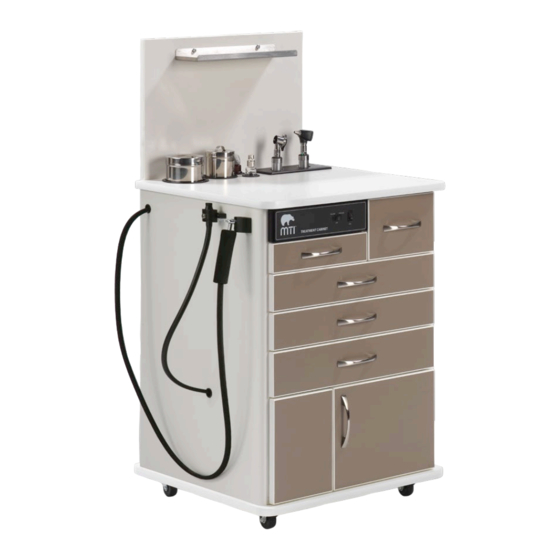
- Page 1 TC100 & TC75 user manual...
- Page 2 THIS PAGE IS INTENTIONALLY BLANK...
-
Page 3: Table Of Contents
Table of Contents APPLICABLE MODEL(S) ................................IV REVISION HISTORY TABLE ................................ IV GENERAL INFORMATION ................................1 Purpose of this Manual ..............................1 Intended Use ..................................1 Training Options ................................. 1 Symbols and Warnings ............................... 2 Symboles et Avertissements .............................. 2 Safety Instructions ................................ -
Page 4: Applicable Model(S)
User Manual | MTI TC Series Cabinets APPLICABLE MODEL(S) This manual is for the following product numbers and serial numbers: PRODUCT NUMBER DESCRIPTION EFFECTIVE S/N TC100AS TC100AS ENT Cabinet, Std Depth Sit-Down All-Current TC100AT TC100AT ENT Cabinet, Slim Depth Sit-Down... -
Page 5: General Information
Training is accomplished either through reading the installation and operation sections of the user manual or through remote training provided by MTI Customer Service. To request training, contact MTI. PRODUCT INFORMATION Date of Purchase:... -
Page 6: Symbols And Warnings
User Manual | MTI TC Series Cabinets Symbols and Warnings Type B applied part This manual contains Notices, Cautions, and Warnings, which Type B, partie appliquée are meant to call attention to particular parts or sections Proper shipping orientation for the product of this manual. - Page 7 Upper and lower limits of relative humidity Limites haute et basse de humidité relative Upper and lower limits of atmospheric pressure Limites haute et basse de la pression atmosphérique Location of fuses Emplacement de fusibles Connection point for the neutral conductor Point de connexion pour le conducteur neutre Connection point for the live conductor Point de connexion pour le conducteur sous tension...
-
Page 8: Safety Instructions
User Manual | MTI TC Series Cabinets Safety Instructions Electrical Requirements WARNING/AVERTISSEMENT WARNING/AVERTISSEMENT Read this manual before installation and use. To avoid risk of electrical shock, this equipment must be connected to a supply mains with protective earth. Lisez ce manuel avant l’installation et l’utilisation. -
Page 9: Contraindications
NOTICE/AVIS Removing the power supply cord at the equipment input or wall receptacle will simultaneously isolate both poles of the power supply. Retrait du cordon d’alimentation à l’équipement ou à la prise murale se isoler simultanément les deux pôles de l’alimentation. Contraindications None. -
Page 10: Equipment Features
User Manual | MTI TC Series Cabinets EQUIPMENT FEATURES Description of TC100 Series Cabinets TC100 Series Cabinets come in 6 basic sizes with each size having a left-hand or right-hand dexterity. The left hand dexterity places the instrument handles and hoses on the left side of the cabinet as you are facing it. The right hand dexterity places the instrument handles and hoses on the right side of the cabinet as you are facing it. - Page 11 Description of TC75 Series Cabinets TC75 Series Cabinets come in 2 basic sizes with each size having a left-hand or right-hand dexterity. The left hand dexterity places the instrument handles and hoses on the left side of the cabinet as you are facing it. The right hand dexterity places the instrument handles and hoses on the right side of the cabinet as you are facing it.
-
Page 12: Installation
User Manual | MTI TC Series Cabinets INSTALLATION NOTICE/AVIS WARNING/AVERTISSEMENT Inspect the shipping boxes for visible damage. Record on This equipment is heavy. Get help to remove it from the shipping bill of lading, photograph, report any damage to the carrier pallet. -
Page 13: Unpacking And Set-Up
Unpacking and Set-up 1. Remove shipping straps and 2. Cut and remove the two 3. Slide the cabinet off the pallet 4. Vacuum and pressure pump shipping box from the pallet. internal banding strips holding by moving the cabinet on the installation: Using the utility knife, cut the the cabinet to the pallet. -
Page 14: Operation
User Manual | MTI TC Series Cabinets Inside of cabinet Inside of cabinet 13. Connect the black suction 14. Connect the patient hose 15. Reinsert the drawer 16. If the cabinet is ordered with hose from the vacuum pump with plastic connector to the removed in step 4. -
Page 15: Electrical Distribution Box
Electrical Distribution Box The electrical distribution box powers all of the electrical components in the cabinet. Listed are all of the components of the box. 1. Auxiliary Fuse 5 Amp: protects the cabinet and its components. If the fuse blows, either the load plugged into the receptacle it too great or there may be a short and a qualified service technician should inspect for a short. -
Page 16: Pressure Hose
User Manual | MTI TC Series Cabinets Pressure Hose Lift-Up Shelf The pressure hose can be located on either the right or left side An optional lift-up shelf can be used for extra counter space. of the cabinet, depending on the cabinet dexterity. The handle The shelf is either 12”... -
Page 17: Accessories Installation
However, verify the product and options against the order since will run. As soon as the pedal is rocked back to the middle, the MTI’s TC Series Cabinets are customizable. pump will stop. Most accessories either come installed on the cabinet before Follow these steps to install the foot pedal in the cabinet: shipping, or they are easily installed out of the box. -
Page 18: Medicine Lock Box
User Manual | MTI TC Series Cabinets Medicine Lock Box 4. While holding the medicine lock box in place, align the (2) mounting brackets to the medicine lock box on the back side of the back wall and attach the mounting brackets with the For shipping purposes, the medicine lock box is not installed on (6) provided lock nuts and (6) washers using a 11/32”... -
Page 19: Vacuum Pressure Evacuation System
Vacuum Pressure Evacuation System The Vacuum Pressure Evacuation System is primarily used when clinicians are using small tips and the high volume vacuum. Portions of this system are pre-installed at the factory. Follow the following steps to complete the installation procedure: 1. -
Page 20: List Of Accessories
User Manual | MTI TC Series Cabinets LIST OF ACCESSORIES DESCRIPTION RESTRICTIONS Cabinet Foot Control Provides a foot operated control for the vacuum and pressure. Canister/Bottle Tower Places the canisters and bottles on the backwall instead of counter top. Central Pressure and/or Vacuum... -
Page 21: Maintenance
MTI understands that many customers prefer to use a pre- qualified service technician. mixed disinfecting solution in a spray or wipe. It is MTI’s Aucune pièce interne ne peut être réparée par l’utilisateur. Adressez- recommendation not to use sprays because over time the vous à... -
Page 22: Preventative Maintenance
Proper filter applied. maintenance will guarantee optimal performance. Replace the MTI ULPA 250™ when the “Replace If Discolored” indicator ring Painted Surfaces has discolored or on two month intervals, whichever comes first. All painted metal parts have been electrostatically painted and the paint is baked on for durability. -
Page 23: Limited Warranty
This warranty does not apply to any part or product which upon examination by MTI or its authorized agents indicates the product has been repaired or altered in any way by persons other than MTI or its authorized agents, has been misused, abused or used in a manner contrary to any instructions issued by MTI. -
Page 24: Troubleshooting Guide
User Manual | MTI TC Series Cabinets TROUBLESHOOTING GUIDE NOTICE/AVIS For more information on this equipment, including circuit diagrams, parts and service manuals, and other descriptions, please contact MTI. Pour plus d’informations sur cet équipement, y compris des schémas de circuits, les manuels de service et pièces, et autres descriptions, s’il vous plaît contacter MTI. -
Page 25: Specifications
For more information on this equipment, including circuit diagrams, parts and service manuals, and other descriptions, please contact MTI. Pour plus d’informations sur cet équipement, y compris des schémas de circuits, les manuels de service et pièces, et autres descriptions, s’il vous plaît contacter MTI. SYMPTOMS PROBLEM CAUSE... -
Page 26: In-Service Form
If you would like to receive occasional emails regarding MTI promotions and product announcements, fill out the sales form at www.mti.net/contact-us. MTI, Inc. 801-875-4999 • Fax 801-952-0548 • www.MTI.net © MTI, Inc. All rights reserved. MTI reserves the right to make any product changes without notice. - Page 27 THIS PAGE IS INTENTIONALLY BLANK...
- Page 28 800-924-4655 • 801-875-4999 • Fax 801-952-0548 www.mti.net © MTI All rights reserved. MTI reserves the right to make any product changes without notice. The MTI brand and Bear logo design are registered trademarks of MTI, Inc. in the United States.
Need help?
Do you have a question about the TC Series and is the answer not in the manual?
Questions and answers