
Subscribe to Our Youtube Channel
Related Manuals for Quectel LC29H Series


Summary of Contents for Quectel LC29H Series
- Page 1 LC29H Series EVB User Guide GNSS Module Series Version: 1.1 Date: 2023-04-26 Status: Released...
- Page 2 GNSS Module Series At Quectel, our aim is to provide timely and comprehensive services to our customers. If you require any assistance, please contact our headquarters: Quectel Wireless Solutions Co., Ltd. Building 5, Shanghai Business Park Phase III (Area B), No.1016 Tianlin Road, Minhang District, Shanghai...
- Page 3 Except as otherwise set forth herein, nothing in this document shall be construed as conferring any rights to use any trademark, trade name or name, abbreviation, or counterfeit product thereof owned by Quectel or any third party in advertising, publicity, or other aspects.
-
Page 4: Safety Information
Otherwise, Quectel assumes no liability for customers’ failure to comply with these precautions. Ensure that the product may be used in the country and the required environment, as well as that it conforms to the local safety and environmental regulations. -
Page 5: About The Document
GNSS Module Series About the Document Document Information Title LC29H Series EVB User Guide Subtitle GNSS Module Series Document Type EVB User Guide Document Status Released Revision History Version Date Description 2021-12-14 Creation of the document 2021-12-20 First official release Updated the EVB version from V1.2 to V1.3. -
Page 6: Table Of Contents
GNSS Module Series Contents Safety Information ............................3 About the Document ..........................4 Contents ..............................5 Table Index ..............................6 Figure Index ..............................7 Introduction ............................8 1.1. Special Mark ..........................9 General Overview ..........................10 2.1. EVB Kit ............................. 10 2.2. - Page 7 GNSS Module Series Table Index Table 1: Special Mark........................... 9 Table 2: List of Kit Components ........................11 Table 3: Detailed EVB Interfaces ....................... 14 Table 4: J401 Pin Description........................15 Table 5: J402 Pin Description........................16 Table 6: QGNSS Interface Explanation...................... 20 Table 7: Related Documents ........................
- Page 8 GNSS Module Series Figure Index Figure 1: EVB Kit Components ........................10 Figure 2: EVB and Components Assembly ....................12 Figure 3: EVB Top View ..........................13 Figure 4: COM Port and Baud Rate Setting ....................18 Figure 5: QGNSS Interface (Connected) ....................19 Figure 6: Tool Startup ..........................
-
Page 9: Introduction
GNSS Module Series Introduction This document provides information on the steps needed to evaluate the Quectel LC29H series module by using the Evaluation Board (EVB). The EVB is a convenient tool that allows you to become familiar with the LC29H series modules. -
Page 10: Special Mark
GNSS Module Series 1.1. Special Mark Table 1: Special Mark Mark Definition Unless otherwise specified, when an asterisk (*) is used after a function, feature, interface, pin name, or argument, it indicates that the function, feature, interface, pin, or argument is under development and currently not supported;... -
Page 11: General Overview
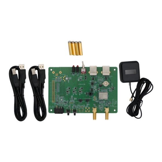
GNSS Module Series General Overview 2.1. EVB Kit The EVB kit includes: Evaluation Board (EVB), active GNSS antenna, Type-B USB cables, bolts and coupling nuts. The EVB kit components are shown in the figure below. Check Table 2: List of Kit Components for details. - Page 12 BDS B1I and B2a ⚫ QZSS L1 C/A and L5 ⚫ SBAS L1 (only LC29H (AA, DA)) Other Bolts and Coupling Nuts 4 pairs ⚫ NOTE Request Quectel Technical Support (support@quectel.com) for details about Quectel Active GNSS Antenna. LC29H_Series_EVB_User_Guide 11 / 38...
-
Page 13: Connect Cables And Antenna To Evb
GNSS Module Series 2.2. Connect Cables and Antenna to EVB The connection between the EVB and its components is shown in the figure below. Figure 2: EVB and Components Assembly ⚫ NOTE It is optional to connect PC and the “POWER SUPPLY” (J201) on the EVB via a Type-B USB. For more information, see Chapter 3.2 EVB Interfaces. -
Page 14: Evb Interfaces
GNSS Module Series EVB Interfaces 3.1. EVB Top View EVB top view is shown in the figure below. S201 (Power switch) J501 (USB to UART) D501 (POWER and VCC indication LEDs) J201 (POWER SUPPLY) D507 (1PPS and TXD indication LEDs) Test point 16 Test point 15 EVB version... -
Page 15: Evb Interfaces
GNSS Module Series 3.2. EVB Interfaces The EVB interfaces are detailed in the table below. Table 3: Detailed EVB Interfaces Function Interfaces Description J201 J201: Only used to supply power to avoid POWER SUPPLY the insufficient supply of J501. J501: Used to communicate and supply Power Supply power. - Page 16 GNSS Module Series Function Interfaces Description Used for WHEELTICK and FWD signals J402 input (only LC29H (BA, CA)). Pins are Others detailed in Table 5: J402 Pin Description. Pin description of J401 is shown below: Table 4: J401 Pin Description Test Point Test...
- Page 17 GNSS Module Series Test Point Test Point Test Point Description Label Function No label No label No label No label PIN23 U601: Pin 23 VCC: Main power supply V_BCKP: Backup power supply for PIN22 U601: Pin 22 backup domain of module Ground Ground PIN21...
- Page 18 GNSS Module Series Pin Number Pin Label Pin Function Description Forward/Backward status signal input (only LC29H (BA, CA)) ⚫ NOTE Test points of J401 are arranged clockwise, and their serial numbers are shown in Figure 3: EVB View. A J401 test point refers to the module’s corresponding function. For detailed descriptions, see document [2] hardware design.
-
Page 19: Testing And Firmware Upgrading Via Qgnss Tool
GNSS Module Series Testing and Firmware Upgrading via QGNSS Tool This chapter explains how to use the QGNSS software tool for verifying the status of GNSS modules and for firmware upgrading. For more information about QGNSS use, see document [4] QGNSS user guide. - Page 20 Figure 5: QGNSS Interface (Connected) ⚫ NOTE Ensure the CP210x driver has been installed when you use the QGNSS tool for the first time. For more information about the driver, please contact the Quectel Technical Support (support@quectel.com). LC29H_Series_EVB_User_Guide 19 / 38...
-
Page 21: Qgnss Interface Explanation
GNSS Module Series 4.2. QGNSS Interface Explanation You can view GNSS information, such as C/N message, time, position, speed, and precision in the QGNSS interface. See the following table to find out more about these parameters. Table 6: QGNSS Interface Explanation Icon Explanation This sky view interface shows the position of the satellites in use. -
Page 22: Firmware Upgrading
GNSS Module Series Icon Explanation ⚫ Longitude (unit: °) ⚫ Latitude (unit: °) ⚫ Altitude (MSL) (unit: m) ⚫ Receiver speed (unit: km/h) ⚫ Horizontal dilution of precision ⚫ Position dilution of precision ⚫ Fix Mode: 2D, 3D ⚫ Quality Indicator: DGNSS, DGPS, GPS SPS, Float RTK and Fixed RTK modes ⚫... - Page 23 GNSS Module Series ② Figure 7: Tool Setting Step 3: Click the “Open Config File” button to select Config file, e.g., “flash_download.cfg”. Figure 8: Firmware Selecting Step 4: Click the “Run” button and then short press the reset button after the progress bar prompts you to reset the module.
- Page 24 GNSS Module Series Figure 9: Firmware Upgrading - 1 Figure 10: Firmware Upgrading - 2 Step 5: Upon successful firmware upgrading, the QGNSS tool’s progress bar on the screen will indicate “100 %”. LC29H_Series_EVB_User_Guide 23 / 38...
- Page 25 GNSS Module Series Figure 11: Successful Firmware Upgrading LC29H_Series_EVB_User_Guide 24 / 38...
-
Page 26: Dr Application
GNSS Module Series DR Application LC29H (BA) and LC29H (CA) support the Dead Reckoning technology. This chapter outlines the implementation of the DR function. Before using the DR function, the module integrated IMU needs to be calibrated. To ensure module performance, the EVB must be mounted properly on the vehicle in such a way that it is firmly attached to the vehicle during use and no relative movement is allowed between the vehicle and the EVB. -
Page 27: Rtk Application
GNSS Module Series RTK Application LC29H (BA), LC29H (DA) and LC29H (EA) support RTK function. This chapter mainly describes how to test the RTK function of the module. Before transferring RTK data, ensure that the connection to server is stable and the COM port and baud rate are set. - Page 28 GNSS Module Series Once the connection is established, the RTK status can be confirmed by querying the quality indicator of the GGA message. 2 indicates that the module entered differential mode, 4 indicates that the module entered Fixed RTK mode, and 5 indicates that the module entered Float RTK mode. Figure 13: RTK Status Display LC29H_Series_EVB_User_Guide 27 / 38...
-
Page 29: Evb And Antenna Installation
GNSS Module Series EVB and Antenna Installation 7.1. GNSS Antenna Installation The installation environment affects the antenna reception performance and satellite visibility, which in turn affect the position quality of a GNSS receiver. In addition, antenna’s orientation can also impact its reception performance. -
Page 30: Measuring Power Consumption
GNSS Module Series Measuring Power Consumption 8.1. Power Consumption at Different Stages Module power consumption is measured in three stages: acquisition and tracking (including almanac update), tracking (almanac update is over) and upon entering Backup mode. ⚫ Acquisition and tracking (including almanac update): 0 s to 12.5 min ⚫... - Page 31 GNSS Module Series Step 2: Switch on the power supply (S201) and read the ammeter. Ammeter Figure 15: VCC Power Consumption Measured with Ammeter Detailed steps for measuring VCC power consumption with a power consumption meter: Step 1: Switch off the power supply (S201) and pull out the VCC_MODULE jumper cap (J601). Make arrow sure the positive pole of the power consumption meter is to be connected to pin 2 (without silkscreen) of J601, and the negative pole is connected to GND.
-
Page 32: V_Bckp Power Consumption Measurement
GNSS Module Series 8.3. V_BCKP Power Consumption Measurement Before measuring the V_BCKP power consumption, you must connect the components to EVB to ensure that the module can communicate and fix normally. See Chapter 4.1 Testing via QGNSS. Detailed steps for measuring V_BCKP power consumption with an ammeter: Step 1: Switch off the power supply (S201) and pull out the V_BACK jumper cap (J202). - Page 33 GNSS Module Series Figure 18: V_BCKP Power Consumption Measured with Power Consumption Meter ⚫ NOTE 1. Adjust the current resolution when using the power consumption meter. 2. Formula for calculating the power value: P = V × I Supply Test 3.
-
Page 34: Evb Framework
GNSS Module Series EVB Framework The power is supplied to EVB via Type-B, and then to the GNSS module via a low-dropout regulator (LDO). GNSS module outputs the signals from communication interface on EVB via USB-to-UART Bridge Chip (CP2102N). There are an antenna interface and control buttons on EVB. All functions of the module are available, including debugging. -
Page 35: Common Problems And Troubleshooting
Verify whether the module is in normal operating mode. ⚫ Check that the downloaded firmware is correct. ⚫ Confirm that the correct COM port has been selected. ⚫ NOTE For the problem(s) that cannot be solved, please contact Quectel Technical Support (support@quectel.com). LC29H_Series_EVB_User_Guide 34 / 38... -
Page 36: Cautions
⚫ Ensure that the measurement method is correct. If there are significant differences between parameters tested via EVB and those provided by Quectel, please contact Quectel Technical Support. ⚫ Note that momentary data obtained from measurement cannot always be regarded as reference data, because it may be affected by various factors, such as satellite positions at different times, environmental conditions, temperature, humidity and altitude. -
Page 37: Appendix References
GNSS Module Series Appendix References Table 7: Related Documents Document Name Quectel_LC29H(BS)_EVB_User_Guide Quectel_LC29H_Series_Hardware_Design Quectel_LC29H_Series_Reference_Design Quectel_QGNSS_User_Guide Quectel_LC29H(BA,CA,DA,EA)_DR&RTK_Application_Note Table 8: Terms and Abbreviations Abbreviation Description Two-dimensional Three-dimensional BeiDou Navigation Satellite System Controller Area Network COM Port Communication Port Carrier-to-noise-density Ratio Direct Current Digital Input Digital Output Dead Reckoning... - Page 38 GNSS Module Series Abbreviation Description Electrostatic Discharge Evaluation Board Galileo Galileo Satellite Navigation System (EU) Ground GNSS Global Navigation Satellite System Global Positioning System GLONASS Global Navigation Satellite System (Russia) Inter-Integrated Circuit Input/Output Light Emitting Diode Mean Sea Level NMEA NMEA (National Marine Electronics Association) 0183 Interface Standard On-Board Diagnostics Personal Computer...
- Page 39 GNSS Module Series Abbreviation Description SubMiniature Version A Standard Positioning Service TTFF Time to First Fix Transmit Data (Pin) UART Universal Asynchronous Receiver/Transmitter Universal Serial Bus Coordinated Universal Time LC29H_Series_EVB_User_Guide 38 / 38...
Need help?
Do you have a question about the LC29H Series and is the answer not in the manual?
Questions and answers