Table of Contents
Advertisement
Quick Links
Service Training Manual
Specifications
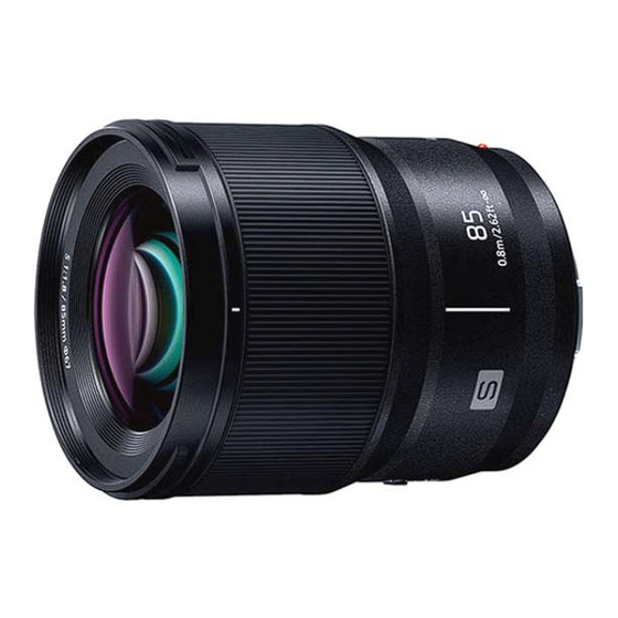
INTERCHANGEABLE LENS FOR DIGITAL CAMERA
"LUMIX S 85 mm F1.8"
Mount
Focal length
Lens construction
Aperture type
Maximum aperture
Minimum aperture value
Angle of view
Recording range
Maximum image magnification
Image stabiliser
Filter diameter
Maximum diameter
Overall length
Mass (Weight)
Dust and splash resistant
Recommended operating
temperature
Permissible relative humidity
S-S85
Component Repair
Leica Camera AG L-Mount
f=85 mm
9 elements in 8 groups
(2 ED lenses)
9 diaphragm blades/circular aperture diaphragm
F1.8
F22
29°
0.8 m (2.62 feet) to ∞ (from the focus distance reference line)
0.13×
No
67 mm
Φ73.6 mm (2.9 inch)
Approx. 82.0 mm (3.2 inch)
(from the tip of the lens to the base side of the lens mount)
Approx. 355 g (0.78 lb)
Yes
-10 ℃ to 40 ℃ (14 ℉ to 104 ℉)
10%RH to 80%RH
ⓒ Panasonic Corporation 2021 Unauthorized copying and distribution is a violation of law.
Ver.1.0
Internal use only
Advertisement
Table of Contents

Related Manuals for Panasonic Lumix S-S85


Summary of Contents for Panasonic Lumix S-S85
- Page 1 Approx. 355 g (0.78 lb) Dust and splash resistant Recommended operating -10 ℃ to 40 ℃ (14 ℉ to 104 ℉) temperature Permissible relative humidity 10%RH to 80%RH ⓒ Panasonic Corporation 2021 Unauthorized copying and distribution is a violation of law.
-
Page 2: Table Of Contents
TABLE OF CONTENTS PAGE 1 Service Navigation ・ ・ ・ ・ ・ ・ ・ ・ ・ ・ 1.1. Introduction ・ ・ ・ ・ ・ ・ ・ ・ ・ ・ 1.2. Important Notice ・ ・ ・ ・ ・ ・ ・ ・ ・ ・ 1.2.1. Overview of Cleaning and Replacing parts ・ ・ ・ ・ ・ ・ ・ ・ ・ ・ 1.2.2. How to treat LENS MAIN UNIT (Ref. No. 220) ・ ・ ・ ・ ・ ・ ・ ・ ・ ・ 2 Exploded View ・ ・ ・ ・ ・ ・ ・ ・ ・ ・ 2.1. Exploded View of Lens Unit ・ ・ ・ ・ ・ ・ ・ ・ ・ ・... -
Page 3: Service Navigation
1 Service Navigation 1.1. Introduction This manual contains technical information, which allow service personnel's to understand and service this model. Please place an order using the parts list and not the drawing reference numbers. 1.2. Important Notice Perform lens cleaning and repair in the clean room (class 10,000) since lens is delicate product and it dislikes a dust. 1.2.1. -
Page 4: How To Treat Lens Main Unit (Ref. No. 220)
1.2.2. How to treat LENS MAIN UNIT (Ref. No. 220) 1. LENS MAIN UNIT (Ref. No. 220) is not eligible for service part, use LENS UNIT (Ref. No. 200) instead. 2. Reuse SHADING FRAME (Ref. No. 205) because it put serial number. B221 B222 B223 B202... -
Page 5: Exploded View
2 Exploded View 2.1. Exploded View of Lens Unit B222 B221 B223 B202 B201 B216 B215 B203 B212 B210 B213 B211 B214 B207 B208 B205 B209 B204 B206 2.2. Precautions for Supply Part To avoid transportation troubles, the following parts come with extra parts. Please discard the extra part when the part is received. -
Page 6: Replacement Parts
3 Replacement Parts ・All parts are supplied from PAVCX Ref.No. Part No. Part Name & Description Remarks DVQL1138Z CE/WEEE LABEL VQL1W22 TEN YEARS LABEL 1 GK LOU4S85CSFCZ LENS UNIT DDE1SS85Z DECORING UNIT DVGE1890Z FILTER RING DVHG1238ZKIT FOCUS RING RUBBER KIT 6SE4SS85Z MOUNT CONTACT UNIT 7DE2Z295Z... -
Page 7: Service Jigs & Tools
T3 type Rp-Chart L-size SUKZ000034 600mm x 800mm Lens Cleaning Kit VFK1900BK Collimeter RFKZ0422 Master Body Purchased locally DC-S1R (Panasonic) Tweezers Purchased locally Plastic or bamboo (Do not use metal) Nipper Purchased locally Tripod Purchased locally Locking glue Purchased locally... -
Page 8: Maintenance
5 Maintenance 5.1. Dust / Dirt on the outer casing part(s) 1. Blow off the dust first, then sweep out the dust from narrower spaces with soft cleaning brush. 2. Wipe up the outer casing part with the dry fuzz-free cloth. 5.2. -
Page 9: Disassembly And Assembly Procedures
6 Disassembly and Assembly Procedures 6.1. Disassembly Procedures 6.1.1 Disassembly Flowchart Lens Unit 3 L Mount 4 Mount Rubber 5 Rear Frame Unit 6 Shading Frame Mount Contact Unit Lens P.C.B. Unit Attention For optical axis adjustment only,perform No.1 and No.2. 1 Decoring Unit Filter Ring Adjustment Screw... -
Page 10: Disassembly Procedure
6.1.2. Disassembly Procedure 6.1.2.3. Removal of L Mount Important Notice: 1. Remove 2 screws (B). Perform lens disassembly in the clean room (class 10,000/ Federal Standard 209D) since lens is Screw (B) delicate product and it dislikes a dust. 6.1.2.1. Removal of Decoring Unit 1. - Page 11 6.1.2.4. Removal of Mount Rubber 6.1.2.6. Removal of Shading Frame 1. Remove Mount Rubber. 1. Remove 3 screws (E) and Shading Frame. Screw (E) Mount Rubber 6.1.2.5. Removal of Rear Frame Unit 1. Remove 3 screws (D) and Rear Frame Unit. Screw (D) Shading Frame Rear Frame Unit...
- Page 12 6.1.2.7. Removal of Lens P.C.B. Unit and 6.1.2.8. Removal of Adjustment Screw and Mount Contact Unit the 1st A Lens Frame Unit 1. Disconnect 3 connectors of Lens P.C.B. Unit. 1. Remove glue around 3 Adjustment Screws. ※ Be careful the dust don't enter in Lens Unit. Connector x...
- Page 13 3. Pull out 3 Adjustment Screws using a nipper with a fine tip since the screw is small. 4. Remove 1st A Lens Frame Unit. 1st A Lens Frame Unit 6.1.2.9. Removal of 3rd B Lens Frame Unit 1. Remove 3 screws (F) and 3rd B Lens Frame Unit. 3rd B Lens Frame Unit Screw (F) x...
-
Page 14: Assembly Procedure
6.2. Assembly Procedure 6.2.1 Assembly Flowchart 1st A Lens Frame Unit 2 3rd B Lens Frame Unit Adjustment Screw Mount Contact Unit Lens P.C.B. Unit 4 Shading Frame 5 Rear Frame Unit 6 Mount Rubber 7 L Mount Attention Perform adjustment before assembling of No.1 or No.2 and then proceed assembly of No.8 and No.9. -
Page 15: Assembly Procedure
6.2.2. Assembly Procedure 6.2.2.2. Installation of 1st A Lens Frame Unit Important notice: and Adjustment Screw 1. When tightening the screw, use a torque driver 1. Install 1st A Lens Frame Unit. (RFKZ0542/RFKZ0456) with specified torque 2. Insert Adjustment Screw using a nipper with a fine tip described in each step. - Page 16 6.2.2.3. Installation of Mount Contact Unit 6.2.2.4. Installation of Shading Frame and Lens P.C.B. Unit 1. Install Shading Frame. 1. Connect FPC of Mount Connect Unit to connector. 2. Tighten 3 screws (E) in numerical order by using the torque driver with specified torque. Lens P.C.B.
- Page 17 6.2.2.5. Installation of Rear Frame Unit 6.2.2.6. Installation of Mount Rubber 1. Install Rear Frame Unit. 1. Install Mount Rubber. 2. Tighten 3 screws (D) in numerical order by using the Mount Rubber torque driver with specified torque. Rear Frame Unit 6.2.2.7.
- Page 18 6.2.2.9. Installation of Decoring Unit 2. Tighten 2 screws (B) in numerical order by using the torque driver with specified torque. 1. Insert the 3 Pins of Decoring Unit to the 3 Hole of Filter Ring. Screw (B) ・Use new one, do not use the one which is removed. ・Double-stick tape sticks to Decoring Unit of repair part.
-
Page 19: Replacement Of Focus Ring Rubber
6.3. Replacement of Focus Ring Rubber 6.3.3. Adhesive applying to fix Focus Ring 6.3.1. Removal of Focus Ring Rubber Rubber 1. Pull Focus Ring Rubber off and cut by scissors a little. 1. Follow the below procedure to apply adhesive at upper Notice: Don't tough Lens Unit to avoid the scratch or and lower side to fix Focus Ring Rubber. -
Page 20: Adjustment
7 Adjustment 7.1. Matrix Table of Necessary Adjustment when Replacing Parts The table shows necessary adjustment when replacing parts. Necessary Adjustment Replacement Part Simple Resolution Electrical Real Time Adjustment Adjustment - - - DECORING UNIT - - - - - - FILTER RING - - - - - -... -
Page 21: Flowchart Of Adjustment
7.3. Flowchart of Adjustment Check for Defective Parts and Internal Dust Disassembly Replacement or Cleaning Assembly Setting to Simple Resolution Real Time Adjustment - Check the brightness and settings of camera - Begin again after Simple Resolution body and test chart Real Time disassembly/assembly - Begin again after... -
Page 22: Procedure Of Adjustment
7.4. Procedure of Adjustment 7.4.1. Equipment and Chart Setting (2) Checking Chart (5) Monitor HDMI cable USB cable (1) LED lamps (4) Capture Board (6) PC Software (3) Lens and Master Body(DC-S1R) Install LED lights left and right symmetrically as uneven illumination does not occur. -
Page 23: Checking Chart Image
7.4.2. Checking Chart Image <Preparation> - Checking Chart (Part No. SUKZ000059) that consisted of 5 charts No.1 - No.5. and 4 black charts. - White plastic matte board /Size: 1,440mm(W) x 960mm(H) or above Guide Line - Length: 500mm or more - Thickness: 5mm or more No.2 No.5... -
Page 24: Master Body(Dc-S1R) Setting And Position
7.4.3. Master Body(DC-S1R) Setting and Position 7.4.3.1 Master Body(DC-S1R) Setting - Cancel the Initial Setting - Set the function parameter to below setting Setting Item Setting value Mode dial A (Aperture-Priority AE Mode) Aperture F 1.8 (Maximum aperture) 【S】([AFS]) Focus mode Image stabilizer White balance AF mode... - Page 25 For more accurate checking, hang the hand glass installed from the upper part of the center of the Checking Chart to the string down, and adjust it to come to the chart center. And If the lens of oneself reflecting in the mirror is displayed in the center of the LCD monitor, placing is correctly.
-
Page 26: Lens Unit Setting
7.4.4. Lens Unit Setting - Set the function parameter to below setting Setting Item Setting value AF/MF switch 7.4.5. PC Software 7.4.5.1 Required PC Specification - OS : Windows 10 - Processor :Pentium 4/M or equivalent - Memory :512 MB RAM - Display :1,024 ×... -
Page 27: Simple Resolution Real Time Adjustment
7.4.6. Simple Resolution Real Time Adjustment Simple Resolution Real Time Adjustment is useful for models which have adjustment screws in 1st Lens Frame Unit. Results are shown in real time, by rotating Adjustment Screws by using Torx Driver (RFKZ0609). ※ Check the visual of Chart on the monitor. 1st Lens Frame Unit Torx driver (RFKZ0609) Adjustment Screw... -
Page 28: Electrical Adjustment
7.4.7. Electrical Adjustment Make Electrical Adjustment using PC with Adjustment Software. As for Adjustment conditions/procedure, consult the "Adjustment Manual" which is available in Adjustment Software. Note: - Download the software package from TSN. - The first time to implement all item - The second time to implement the only BF Adjustment 7.4.8. - Page 29 RP Chart L-Size 600x800mm (SUKZ000034)
-
Page 30: Revision History
8 Revision History Ver. Date History 2021.05.13 ・First Issue...
Need help?
Do you have a question about the Lumix S-S85 and is the answer not in the manual?
Questions and answers