Table of Contents
Advertisement
Advertisement
Table of Contents
Troubleshooting

Related Manuals for THOMSON TS 880


Summary of Contents for THOMSON TS 880
- Page 1 TS 880 AUTOMATIC TRANSFER SWITCHES INSTALLATION, OPERATING & SERVICE MANUAL PM064 REV 8 10/01/25 Street, Langley, BC Canada V1M 3B1 Ÿ Telephone (604) 888-0110 9087A – 198 Telefax (604) 888-3381 Ÿ E-Mail: info@thomsontechnology.com Ÿ www.thomsontechnology.com...
-
Page 3: Table Of Contents
4.2. TYPICAL COMMISSIONING PROCEDURES GENERAL THEORY OF OPERATION 5.1. STANDARD AUTOMATIC TRANSFER SWITCH 5.1.1. NORMAL SEQUENCE OF OPERATION - OPEN TRANSITION 5.1.2. NORMAL SEQUENCE OF OPERATION - CLOSED TRANSITION 5.2. SERVICE ENTRANCE AUTOMATIC TRANSFER SWITCH 5.2.1. NORMAL OPERATION 5.2.2. OVER CURRENT TRIP 5.2.3. - Page 4 7.2.1. GENERAL DESCRIPTION 7.2.2. EQUIPMENT INSPECTION 7.2.3. MANUAL OPERATION 7.2.4. RECOMMENDED MAINTENANCE 7.3. SERVICING – 800A – 4000A INSULATED CASE TYPE TRANSFER MECHANISMS 7.3.1. GENERAL DESCRIPTION 7.3.2. EQUIPMENT INSPECTION 7.3.3. MANUAL OPERATION 7.3.4. RECOMMENDED MAINTENANCE FRONT VIEW (TYPICAL) 3 POLE 100A-250A S STYLE TRANSFER MECHANISM FRONT VIEW (TYPICAL) 3 POLE 400A-1200A T STYLE TRANSFER MECHANISM 10.
- Page 5 (ALL MODELS WITH INTEGRAL OVERCURRENT PROTECTION OPTION) 14. GROUND FAULT SITE TEST REQUIREMENTS 14.1. PERFORMANCE TEST 15. TROUBLESHOOTING (100A-1200A MOLDED CASE SWITCH TYPE ATS) 16. TROUBLESHOOTING (800A-4000A INSULATED CASE SWITCH TYPE ATS) 17. POWER SWITCHING DEVICE TROUBLESHOOTING (800A-4000A INSULATED CASE SWITCH TYPE ATS) 18.
-
Page 7: Product Revision History
Requirements Contact Thomson Technology, to obtain applicable instruction manuals or if in doubt about any matter relating to installation, operation or maintenance. Soft copy of the most current version is available at www.thomsontechnology.com. NOTE: All information contained in this manual is for reference only and is subject to change without notice. -
Page 8: Equipment Storage
2.1.1. EQUIPMENT STORAGE The transfer switch shall be stored in an environment with a temperature range not exceeding -4° to +158° Fahrenheit (-20° to +70° Celsius) and a humidity range not exceeding 5%-95% non-condensing. Before storing, unpack sufficiently to check for concealed damage. -
Page 9: Transfer Switches With Integral Over Current Protection
For models of transfer switch with integral over current protection, the over current protection must be set prior to operation. The equipment will be shipped from the factory with a long-time current setting of 100% (of the equipment rating) and maximum short- time/instantaneous current and time delay settings. -
Page 10: System Phasing-High Leg Delta Systems
Complete the blank calibration label and attach to the inside of the transfer switch enclosure door. 3.4. SYSTEM PHASING-HIGH LEG DELTA SYSTEMS For systems using high leg delta 240V 3 phase 4 wire systems, connection of supply conductors must have the correct phasing as shown below. WARNING! Failure... -
Page 11: Remote Start Contact Field Wiring
(A Phase for both supplies). Failure to do so will result in equipment damage. Per NEC Article 384-3 (f) “The B phase shall be that phase having the higher voltage to ground on a 3-phase, 4-wire delta connected systems.”... -
Page 12: Dielectric Testing
"Standard" enclosures are all transfer switch enclosures Thomson Technology offers in NEMA 1, NEMA 2, NEMA 3R and NEMA 4X for the above listed product. If a customer requests a custom enclosure it would not be covered under the generic certificate;... - Page 13 TS 880 TRANSFER SWITCH PM064 REV8 10/01/25 Thomson Technology...
- Page 14 4. Expansion anchors as shown. To be installed according to manufacturer's recommendation. 5. The 800-1200A NEMA 3R ATS enclosure may be floor/wall mounted or it may be free standing (floor mounted only); If free standing it must be a minimum of 12"...
-
Page 15: General Description
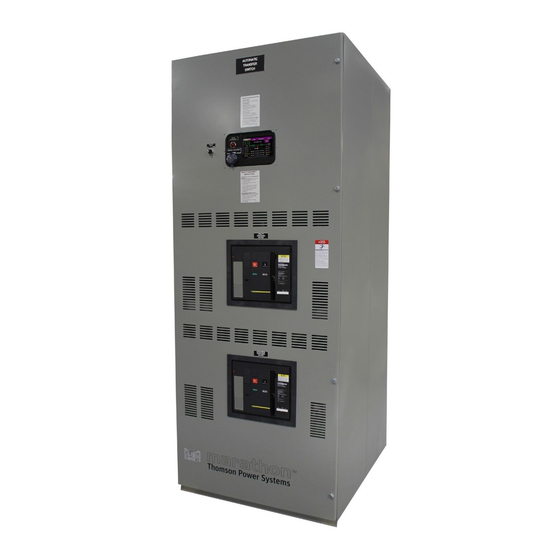
The TSC 800 controller is mounted on the door of the transfer switch enclosure and operating status is shown via LED lights and LCD display module. For further information on the TSC 800 Transfer Controller, refer to instruction manual PM049. -
Page 16: Product Model Code
4.1. PRODUCT MODEL CODE The type of TS 880 series transfer switch supplied is identified by way of a 21 digit product code which appears on the equipment rating plate (MODEL) on the door of the transfer switch, and on the transfer switch drawings. The model code structure and definitions are as follows: 1-3. -
Page 17: Typical Commissioning Procedures
When utility supply voltage drops below a preset nominal value (adjustable from 70% to 99% of nominal) on any phase, an engine start delay circuit is initiated and the transfer to utility supply signal will be removed (i.e. contact opening). Following expiry of the engine start delay period (adjustable from 0 to 60 sec.) an engine start... -
Page 18: Normal Sequence Of Operation - Closed Transition
(i.e. contact opening). Following expiry of the engine start delay period (0 - 60 sec. adjustable) an engine start signal (contact closure) will be given. - Page 19 When the utility supply voltage is restored to above the present values (70 - 99% of rated adjustable) on all phases, a re-transfer sequence will be initiated once the Utility Return timer expires. The utility will close its power switching device when it is in synchronism with the generator supply via external logic device.
- Page 20 1. Transfer Control Switch (Open/Closed Transition): A two position selector switch is provided on the front of the transfer switch for operator section of desired operation. The 2 positions are as follows: §...
- Page 21 TS 880 TRANSFER SWITCH Note: The standard closed transition transfer switch does not contain an automatic synchronizer to control the generators frequency or voltage to bring it within limits of the sync check relay. For correct closed transition transfer operation, the system requires the generators frequency to be set within 0.25% of nominal frequency and...
-
Page 22: Service Entrance Automatic Transfer Switch
5. Transfer Fail Alarm (Switching Device Fail to Close): A control timer (TFT) is provided to detect and alarm abnormal operating conditions. Should a power switching device fail to close for any reason within a 5 minute time period, an alarm light and alarm relay contact will be activated. The TSC 800 transfer controller also includes a time delay and alarm feature. -
Page 23: Over Current Trip
TSC 800 transfer controller will initiate an engine start signal and will permit transfer of the load to the generator supply. The utility source will be locked out and the load will remain on the generator supply until the TSC 800 alarm signal is manually reset. - Page 24 4. To reenergize the load, remove the padlock(s) from the service disconnect control switch, and move the switch to the energized position. The transfer switch will immediately return to the utility or generator supply if within normal operating limits. PM064 REV8 10/01/25...
-
Page 25: Additional Procedures
Equipment (PPE). Failure to do so may cause personal injury or death 1. On 100A-1200A molded case power switching unit type transfer switches, open the door to the transfer switch using a suitable tool and open the door lock with the key. - Page 26 On position. 3. If the position of the 100A-1200A rated transfer switch mechanism is not in the "neutral position", manually operate the transfer switch mechanism depending on mechanism type as follows: Note: Refer to product drawings in sections 12, 13 &...
-
Page 27: Test Modes
Note: The transfer switch will automatically return to the utility supply (if within nominal limits) if the generator set fails while in the test mode. -
Page 28: Standard Ts 880 Automatic Transfer Switch
Section 13 of this manual. The standard TS 880 transfer switch model without integral over current protection is identified in the product model code. Refer to Section 4.1 of this manual for further details on model coding. -
Page 29: Servicing Transfer Switch Mechanisms
Equipment (PPE). Failure to do so may cause personal injury or death Failure to correctly maintain an automatic transfer switch may present a hazard to life and equipment. Full operational testing must be done prior to placing a transfer switch in service subsequent to any maintenance or repair. -
Page 30: Equipment Inspection
All control devices are adequately secured in their plug-in fixtures. Failure to correctly maintain an automatic transfer switch may present a hazard to life and equipment. Full operational testing must be done prior to placing a transfer switch in service subsequent to any maintenance or repair. -
Page 31: Recommended Maintenance
With all sources of power de-energized to the transfer switch, the control circuit isolation plug can be unplugged to prevent subsequent operation. The control circuit isolation plug is located on the inner side of the transfer switch enclosure door. -
Page 32: Servicing- 400A-1200A Molded Case Type Transfer Mechanisms
Transfer switches should be in a clean, dry and moderately warm location. If signs of moisture are present, dry and clean transfer switch. If there is corrosion, try to clean it off. If cleaning is unsuitable, replace the corroded parts. Should dust and/or debris gather on the transfer switch, brush, vacuum, or wipe clean. -
Page 33: Equipment Inspection
Ensure that power switching device travel far enough to reset any internal trip unit. Note: It is more important for the toggle to go fully in the "off" direction, than in the "on" direction. -
Page 34: Manual Operation
With all sources of power de-energized to the transfer switch, the control circuit isolation plug can be unplugged to prevent subsequent operation. To operate manually, pull the release plunger and operate the handle in the desired direction. -
Page 35: Servicing - 800A - 4000A Insulated Case Type Transfer Mechanisms
Ø Verify all program settings on the TSC 800 controller as per the programming sheet as supplied with the transfer switch. Ø Ensure that the manual handle moves freely on the hub when the lock pin is disengaged. If lubrication is necessary, apply medium weight (SAE 20) oil sparingly. -
Page 36: General Description
To maintain mechanical integrity, ensure that: All linkages are correctly adjusted. Mechanical interlocking is correct - it should not be possible to close a power switching unit without first opening the other power switching unit. All fasteners are adequately tightened. -
Page 37: Manual Operation
To transfer manually to generator - turn the System Operation Mode selector to MANUAL, manually start the generator, open the utility power switching device, close the generator power switching device, using open/close pushbuttons. -
Page 38: Recommended Maintenance
TS 880 TRANSFER SWITCH To transfer manually to utility – place the local generator controls in manual/run to ensure continued operation, turn the System Operation Mode selector to MANUAL, open the generator power switching device, close the utility power switching device, using open/close pushbuttons. -
Page 39: Front View (Typical) 3 Pole 100A-250A S Style Transfer Mechanism
TS 880 TRANSFER SWITCH FRONT VIEW (TYPICAL) 3 POLE 100A-250A S STYLE TRANSFER MECHANISM PM064 REV8 10/01/25 Thomson Technology... -
Page 40: Front View (Typical) 3 Pole 400A-1200A T Style Transfer Mechanism
TS 880 TRANSFER SWITCH FRONT VIEW (TYPICAL) 3 POLE 400A-1200A T STYLE TRANSFER MECHANISM PM064 REV8 10/01/25 Thomson Technology... -
Page 41: Front View (Typical) 3 Pole 800A-4000A Insulated Case Type Transfer Mechanism
PRESS *ENTER*, SCROLL TO (MANUAL TEST MENU), PRESS *INCREMENT*, SELECT (YES), PRESS *ENTER*, PRESS *INCREMENT*, SELECT (ON LOAD) OR (OFF LOAD) TEST, PRESS *ENTER* TO INITIATE THE TEST. TO EXIT THE TEST MODE: PRESS *ENTER*, SCROLL TO (MANUAL TEST MENU), PRESS *INCREMENT*, SELECT (YES), PRESS *ENTER*, PRESS *INCREMENT*, SELECT TEST OPTION (NONE), PRESS *ENTER* TO EXIT TEST MODE. -
Page 42: Connection Configuration Options
TS 880 TRANSFER SWITCH CONNECTION CONFIGURATION OPTIONS PM064 REV8 10/01/25 Thomson Technology... -
Page 43: Cable Terminal Information
TS88xA-0800 2/0–500MCM TS88xA-1000/1200 4/0–500MCM TS88xA-0800/4000 As Req’d #2–600MCM 1. With molded case power switching units 2. With insulated case power switching units 3. For other model types not shown, contact Thomson Technology for further information. PM064 REV8 10/01/25 Thomson Technology... -
Page 44: Requirements For Upstream Circuit Protective Devices
3. For other ratings, contact Thomson Technology for further information 4. IEC Rating Fuse ratings shown are maximum allowable to permit use of the transfer switch in application with available fault current not exceeding that shown. Consideration must be given to fuse sizing when fuses also provide overload protection. -
Page 45: Interrupting Capacity Current Ratings (All Models With Integral Overcurrent Protection Option)
Per NEC and UL1008, a ground fault protected system shall be performance tested when first installed on site. A written record of this shall be made and be available to the authority having jurisdiction. A form is provided at the back of this manual for this purpose – see Section 24. -
Page 46: Performance Test
As indicated in the NEC, the maximum setting of the ground fault protection shall be 1200 amps, and the maximum time delay shall be 1 second for ground faults equal to or greater than 3000 amps. - Page 47 TS 880 TRANSFER SWITCH PM064 REV8 10/01/25 Thomson Technology...
- Page 48 - TSC 800 has incorrect voltage programmed for system voltage - Warmup time delay function has not timed out yet (verify TSC 800 timer setting) - A loose control connection - Faulty motor limit switch - Defective motor - Defective TSC 800 controller (verify output signals with circuit board mounted diagnostic LED’s)
-
Page 49: Troubleshooting (800A-4000A Insulated Case Switch Type Ats)
NOTE: There are no user serviceable components located on the TSC 800 printed circuit board. If the TSC 800 controller is deemed to be defective it must be returned to the Thomson Technology Factory for repair or replacement. Please refer to Section 22 for further detailed on product return procedures required. - Page 50 Power is not available at the load The Power Switching Device (service entrance type ATS) has opened due to a fault on the system and TSC 800 “Transfer Fail” terminals but the utility or is programmed as “Disabled or Halt Transfer”. Correct the fault, generator power switching unit and manually reset the power switching unit.
-
Page 51: Power Switching Device Troubleshooting (800A-4000A Insulated Case Switch Type Ats)
It is impossible to extract The racking handle is remained Remove the racking handle and put it in its inserted. storage. the right side rail (on chassis alone) or the power switching device. - Page 52 TS 880 TRANSFER SWITCH MALFUNCTIONS PROBABLE CAUSES CORRECTIVE ACTIONS There is a padlock or a key-lock Remove disabling. for connected or disconnected position. There is a racking interlock. There is an extraction locking It is impossible to extract Discharge the power switching device...
-
Page 53: Power Switching Device Drawing
TS 880 TRANSFER SWITCH POWER SWITCHING DEVICE DRAWING PM064 REV8 10/01/25 Thomson Technology... -
Page 54: Drawout Chassis Engineering Drawing
TS 880 TRANSFER SWITCH DRAWOUT CHASSIS ENGINEERING DRAWING PM064 REV8 10/01/25 Thomson Technology... -
Page 55: Electrical Diagrams
TS 880 TRANSFER SWITCH ELECTRICAL DIAGRAMS PM064 REV8 10/01/25 Thomson Technology... - Page 56 TS 880 TRANSFER SWITCH PM064 REV8 10/01/25 Thomson Technology...
- Page 57 TS 880 TRANSFER SWITCH PM064 REV8 10/01/25 Thomson Technology...
-
Page 58: Replacement Parts
TS 880 TRANSFER SWITCH REPLACEMENT PARTS Replacement parts are available for the transfer switch as follows: NOTE When ordering replacement parts please provide the following information: -Transfer Switch Model code (e.g. TS 883AA0200AS) -Transfer Switch Serial Number (e.g. W-022345) The above information can be found on the transfer switch rating plate located on the outside of the ATS door. -
Page 59: Product Return Policy
Returns only: Sales Fax (604) 888-5606 Warranty replacement/Warranty Repair: Service Fax (604) 888-3370. Upon receipt of your request, Thomson Technology will confirm with a copy of our Order Acknowledgement via fax advising the RMA number which should be used to tag the defective controller prior to shipment. -
Page 60: Notes
TS 880 TRANSFER SWITCH NOTES PM064 REV8 10/01/25 Thomson Technology... -
Page 61: Performance Test Form
TS 880 TRANSFER SWITCH PERFORMANCE TEST FORM This form should be retained by those in charge of the building electrical installation in order to be available to the authority having jurisdiction. Date Personnel Tests performed Comments Interconnection evaluation Grounding point evaluation... - Page 63 Verify supply source voltage to be applied to the transfer switch is of the correct nominal value. Confirm this to be the same as listed on the ATS drawings and the ATS equipment label. For other system voltages refer to the ATS instruction manual for re-configuring procedures prior to energization.
- Page 64 11) Set the TSC 800 time clock, as there is no battery installed on the circuit board. The time clock is a 7 day, 4 week, 24 hour clock. Refer to the TSC 800 manual for time clock programming instructions. The TSC 800 time clock is used for automatic exercise load testing.
- Page 65 3-second neutral delay period, then the mechanism will complete the transfer and close the Utility power switching device to return the load to the Utility source. Once the load has transferred onto the utility source, the engine will continue to run for the 2-minute cool down time delay period and will then it will automatically stop.
- Page 67 APPENDIX “B” THOMSON TECHNOLOGY © SEISMIC CERTIFICATE 9087A - 198 Street, Langley, B.C. Canada V1M 3B1 Telephone (604) 888-0110 Telefax (604) 888-3370...
Need help?
Do you have a question about the TS 880 and is the answer not in the manual?
Questions and answers