
Related Manuals for XFit SECTOR


Summary of Contents for XFit SECTOR
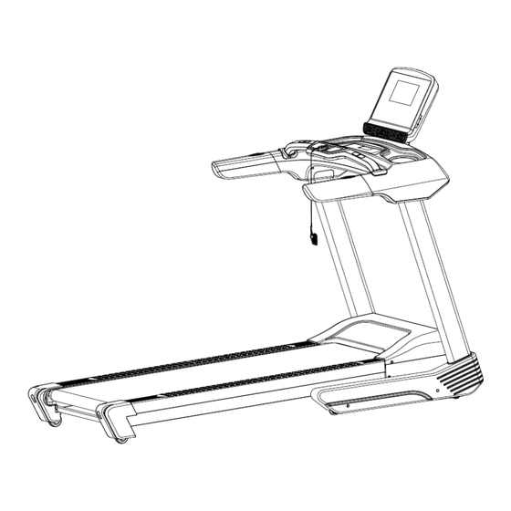
- Page 1 Treadmill User’s Manual * Product specifications may differ from the photo and are subject to change without notice.
- Page 2 - 1 -...
- Page 3 WARNING Read all instructions carefully before using this product. Retain this owner’s manual for future reference: ----When using this treadmill, keep attaching the safety pull pin rope to your clothes. IMPORTANT: The SAFETY KEY has a magnet which is connected to the console. At the other end there is a clip that must be placed on your clothes.
- Page 4 IMPORTANT SAFETY PRECAUSTIONS 1. Plug the power cord of the treadmill directly into a dedicated grounded circuit. This product must be grounded. If it has breakdown, grounding provides a path of least resistance for electric current to reduce the risk of electric shock. 2.
-
Page 5: Assembly Steps
17. If the supply cord is damaged, it must be replaced by the manufacturer, its service agent or similarly qualified persons in order to avoid a hazard. 18. Put your feet on the side rail before using the treadmill, and always attach the safety pull pin rope to your clothing. - Page 6 STEP 2: 1. Connect the computer lower wire(92)and computer extension lower wire (93). 2. Insert and lock the upright tube (3L/R) on the bottom frame (1) with the hex socket screws (55) (59) and the Lock washer (80) (81). NOTE: please don’t tighten the Hex socket screw (55) (59) for the time being. - 5 -...
- Page 7 STEP 3: 1. Connect the computer extension upper wire (94) with the extension lower wire (93). 2. Lock the computer frame (4) on the upright tube (3L/R) with the hex socket screws (55) and Lock washer (80). NOTE: please don’t tighten the Hex socket screw (55) for the time being. - 6 -...
- Page 8 STEP 4: 1. Connect the wire of armrest (6) with the wire of computer frame (4) properly well. 2. Secure the armrest (6) to computer frame (4) with the hex socket screws (55) and Lock washer (80). 3. Separate armrest decorative cover(35L/R ) from the opening, then put on the joint of armrest (6) and computer frame(4) respectively.
- Page 9 STEP 5: 1. Connect the wire of Computer panel (29) and Computer frame (4) properly well. (Wires of the same order are joined together as picture A shown). 2. Using Hex socket screw (59) to secure the Panel bracket (5) on Computer frame (4). 3.Using Cross tapping screw (73) to secure the Computer panel joint cover (32) to Computer panel lower cover (30).
- Page 10 STEP 6: 1. Secure the protective cover (26L /R) to the bottom frame (1) with Cross tapping screw (73). 2. Stuck protective cover (37L /R) to the card slot of computer lower cover (28). - 9 -...
- Page 11 When you fold the machine: Put your hands on place A, lift up the machine in the direction of the arrow until you hear the sound from the cylinder (14). Note: Please unplug the power cord and make sure treadmill stopping completely before folding machine.
-
Page 12: Grounding Methods
GROUNDING METHODS This product must be grounded. If it should malfunction or breakdown, grounding provides a path of least resistance for electric current to reduce the risk of electric shock. This product is equipped with a cord having an equipment-grounding conductor and a grounding plug. The plug must be plugged into an appropriate outlet that is properly installed and grounded in accordance with all local codes and ordinances. -
Page 13: Function Specifications
OPERATION INSTRUCTIONS 1. Function specifications 1.1. Start Normal start up after 3s counting backwards. 1.2. Number of programs Manual Modes, 18 Preset programs, 3 User setting programs, HRC1-HRC3,FAT. 1.3. Safe lock function Remove the safety lock in any modes could rapidly slow down the treadmill till stop. “---”... -
Page 14: Key Function
1.4. LCD windows display functions: A. Speed/pulse window: Display the current running speed or current pulse. B.INCL./PROG. Window: Display the current incline or programs. C.TIME Window: Display the running time under manual mode or the countdown running time under mode and programmed mode. D.DIS./CAL./STEPS Window: display distance,calorie or steps data. -
Page 15: Heart Rate Measurement Function
1.6 Data display range of various parameters: TIME: 0:00 – 99.59(MIN) DISTANCE: 0.00 – 99.9(KM) CALORIES: 0.0 – 999 (KC) SPEED: 1.0 – 20.0(KM/H) PULSE: 50 – 200 (BPM) INCLINE: 0-15 1.7. Heart rate measurement function While the treadmill is connected to the power, hold the pulse tester for 5s and the heart rate value will be displayed. -
Page 16: Preset Programs
5s later, the machine will return to the standby state and the buzzer will make long alarm “Bi-Bi”. G. Parameters not set will increase forwards and will be reset after reaching the upper limit of the display range; in manual mode, the machine will stop when the time accumulates to be more than 99: 59 (100min). -
Page 17: Body Fat Test
SPEED INCLINE SPEED INCLINE 1.10. User-setting programs: Beside the 18 inner systems, the treadmill setup 3 user-defined programs: U1, U2, U3. 1. Setting the user-defined program: Continuously press "PROG" key until the expected program (U1/U2/U3) display in the standby condition, while the "time" window flash, display the setting time, press “SPEED+”, “SPEED -”to set up expected run time, press "MODE"... - Page 18 1.31. Others 1.13.1. When a countdown parameter run off, display "END", the alarm rings 0.5s every 2s, until the treadmill full stop, then return to manual mode. 1.13.2. In setting a parameter, it can be loop-setting, for example, time range is 5:00--99:00, when set at 99:00, press "+"...
-
Page 19: Exercise Instructions
EXERCISE INSTRUCTIONS 1. The Warm Up Phase This stage helps get the blood flowing around the body and the muscles working properly. It will also reduce the risk of cramp and muscle injury. It is advisable to do a few stretching exercises as shown below. -
Page 20: Maintenance Instructions
MAINTENANCE INSTRUCTIONS WALKING BELT CENTERING AND TENSION ADJUSTMENT DO NOT OVERTIGHTEN the walking belt. This may cause reduced motor performance and excessive roller wear. TO CENTER WALKING BELT: ● Place treadmill on a level surface ● Run treadmill at approximately 3.5 mph ●... -
Page 21: Lubrication Instructions
LUBRICATION INSTRUCTIONS WARNING! Always unplug the power cord before performing any maintenance on your treadmill. CLEANING: Regular cleaning of your treadmill will extend its life. WARNING! To avoid electric shock, make sure the treadmill is off and the power cord is unplugged before cleaning or maintenance. -
Page 22: Exploded Drawing
EXPLODED DRAWING PARTS LIST - 21 -... -
Page 23: Part List
PART LIST Part Part Description Description Bottom frame Hex socket screw M8*45 Main frame Hex socket screw M8*40 3 L/R Upright tube Hex socket screw M8*15 Computer frame Hex head cap screw M10*35 Panel bracket Hex head cap screw M8*25 Armrest Hexagon socket head cap screws M6*45 Incline frame... - Page 24 Protective plug Inverter Cushion Switch Power wire buckle Circuit breaker Adjusting wheel Power wire Square end cap Flap Belt Nylon spacer Wheel D-shaped nylon spacer Anti-skidding mat Loudspeaker (Optional) Plastic pad USB (Optional) Hex socket screw M10*55 MP3/ Headphone (Optional) Hex socket screw M10*55 Inductor (Optional) Hex socket screw M10*40...
- Page 25 TERMS OF WARRANTY • Warranty period is 5 years for motor, 2 years for electrical / electronic parts and 5 years for the metal frame. • X-TREME STORES S.A. undertakes to repair the machine free of charge in the event of damage due solely to a manufacturing fault.
- Page 26 NOTES - 25 -...
- Page 27 - 26 -...
- Page 28 34 koupi Avenue, Koropi P.C.:19441 - P.O. Box 6201 Tel.: 210 66 20 921 -2 - Fax: 210 66 20 923 E-mail: info@xtr.gr • f/xtrstores • /@xtr.gr Tel. for all of Greece: 801.11.15.100 www.xtr.gr - 27 -...
Need help?
Do you have a question about the SECTOR and is the answer not in the manual?
Questions and answers