Table of Contents
Advertisement
Quick Links
Advertisement
Table of Contents

Related Manuals for CHCNAV NX510


Summary of Contents for CHCNAV NX510
- Page 1 CHCNAV NX510 USER MANUAL Precision Agriculture | Feb 2024...
-
Page 2: Table Of Contents
Table of Content Preface ........................... 5 Copyright ....................5 1.1.1 Copyright 2023-2024 ................. 5 1.1.2 Trademarks ..................5 Safety Warning ..................5 Conformity to National Regulations............6 1.3.1 FCC declaration of conformity ............6 1.3.2 Conformity to Japanese regulations ..........6 1.3.3 EU ....................... - Page 3 3.2.11 ER-2 external Rx radio installation ........... 22 Software Functions ....................24 Main interface ..................24 System Settings ..................30 4.2.1 Guidelines ..................30 4.2.1.1 Guidelines Main Interface ..........30 4.2.1.2 New ..................33 4.2.1.3 U-Turn ................39 4.2.2 Farms ....................42 4.2.2.1 Farms Main Interface ............
- Page 4 4.2.11.5 Backup and Restore Settings ..........88 4.2.11.6 Parameters ................. 89 4.2.11.7 Set Parameter ..............89 4.2.12 APN Setting ..................89 4.2.13 Safety ....................90 4.2.13.1 Maximum autopilot speed ..........90 4.2.13.2 Max speed allowed to enable auto steering mode ... 91 4.2.13.3 Manual override ..............
-
Page 5: Preface
All product and brand names mentioned in this publication are trademarks of their respective holders. 1.2 Safety Warning When using the CHCNAV NX510 SE/Pro/Plus GNSS Auto Steering System, please observe the following safety warnings: Before using the system, carefully read and understand the operating instructions in the user manual to ensure proper use of the system. -
Page 6: Conformity To National Regulations
The above is for reference only, and specific safety warning content may vary slightly depending on the device model and local regulations and standards. When using the CHCNAV NX510 SE/Pro/Plus GNSS Auto Steering System, please carefully read and observe the relevant safety warnings and usage instructions to ensure the safety and normal operation of the system. -
Page 7: Anatel
1.4 Introduction The CHCNAV NX510 user manual describes how to install and use the CHCNAV® NX510 system. In this manual, “the system” refers to the NX510 agricultural system unless otherwise stated. Even if you have used other agricultural products before, CHCNAV recommends that you spend some time reading this manual to learn about the special features of this product. -
Page 8: Disclaimer
Before using the system, please make sure that you have read and understood this User Guide, as well as the safety information. CHCNAV holds no responsibility for the wrong operation by users and for the losses incurred by the wrong understanding about this User Guide. -
Page 9: Main Components
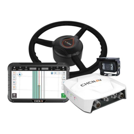
2.2 Main Components Receiver: It is typically a Global Navigation Satellite System (GNSS) receiver, used to receive satellite signals to determine the accurate position, direction, and speed of the vehicle. It forms the foundation for autosteering system by providing precise information about the current location of the vehicle. -
Page 10: Installation
3 Installation 3.1 Product Package All components are into one box. First Layer of NX510: Second Layer of NX510: List of components: Device name Model Image Quantity Electric steering wheel CES-T Receiver PA-3 Tablet CB-H10... - Page 11 Wheel angle sensor GASensor Camera F23A220-FC Ball holder Double socket arm Standard bracket T-bracket T mount kit (A&B) Integrated main cable Wheel angle sensor cable Camera cable Radio Antenna...
-
Page 12: Installation Steps
3.2 Installation Steps 3.2.1 List of tools Tools Materials Image Quantity Purpose H6-6mm hexagon M8*60 inner Fix T mount kit (A&B) screwdriver hexagon screw PH2-5mm Phillips M5*11 Phillips Fix the sleeve to electric steering screwdriver screw wheel 16mm spanner M10 nut Fix the T-bracket to T mount kit M5*16 outer 8mm spanner... -
Page 13: Steering System Inspection
Before installation, please check whether the vehicle steering gear is normal, whether the dead zone (steering clearance) is appropriate. Available range Dead zone<20° Available to install NX510 but necessary to modify the dead 20°<Dead zone<70° zone to 10~30 degrees. Dead zone >70°... -
Page 14: Steering Wheel Installation
d) Before install the sleeve into the steering wheel, please try it on the spline to check whether the size fits. 3.2.4 Steering wheel installation a) If the sleeve can fit the spline, please remove the protective cover of the steering wheel, place the sleeve in it, and fix the sleeve with M5*11 phillips screws (6 pcs);... - Page 15 b) Install T bracket or standard bracket on the motor with M5*16 hexagon screws (2 pcs); c) Fix the T mount kit to the shaft with M8*60 hexagon screws (2 pcs); d) Insert T bracket through T mount kit; e) Hold the steering wheel and tighten the spline screws with tools;...
-
Page 16: Receiver Installation
f) Screw the T bracket to the T mount kit tightly with M10 nuts (2 pcs); g) Finally shake the steering wheel, check whether it’s tight, and check again whether the steering clearance is too large. 3.2.5 Receiver installation a) The receiver needs to be installed on the central axis of the vehicle roof as possible, and the installation direction should be parallel to the vehicle as possible;... -
Page 17: Tablet Installation
3.2.6 Tablet installation The tablet installation requires the ball base to be installed in locations as suggested shown in the picture, and avoid damaging to the original vehicle cables. Usually there are two kinds of installation methods to fix the mounting bracket. a. - Page 18 c) After complete the installation, it is available to adjust the tablet to a suitable position;...
-
Page 19: Wheel Angle Sensor Installation
3.2.7 Wheel angle sensor installation a) It is recommended to fix the wheel angle sensor as horizontal as possible on the right steering wheel which avoids collision with the vehicle; b) Pay attention to install the mount plate on the wheel platform. 3.2.8 Camera installation The camera can be installed anywhere (within the wire harness length range). -
Page 20: Cables Connection
3.2.9 Cables connection Name Cable diagram Connection A → Receiver B → Motor C → Wheel angle sensor Integrated cable main D → Tablet Port 3 cable E → Battery F → Tablet Port 1 G: Rocker switch H → Camera Camera I →... - Page 21 · When wiring, first arrange the outer wiring harnesses, then arrange the wiring harnesses in the cab; · When wiring, pay attention to avoid high temperature, oily, sharp and abrasive areas, fans, exhaust pipes and other nearby areas; · When wiring, keep a certain length to avoid over-tightening and loosening; the wiring harnesses layout should be smooth and cannot be twisted;...
-
Page 22: Radio Antenna Installation
ER-2 Rx radio to receive data from the base station. a) Before install the radio module, please turn off the power of the NX510 system. b) The ER-2 product package includes external radio module, radio antenna, wiring harness. - Page 23 The wiring harness connection is as below, 1 means radio antenna port; 2 means communication port; 3 means tablet port3; 4 connects to main cable; 5 means two AMP ports for other CHCNAV devices and not useful for NX510PRO/PLUS.
-
Page 24: Software Functions
Software configuration please refer to Chapter 4.2.7.1 Internal & External Radio 4 Software Functions 4.1 Main interface 1. Satellite status. There are two numbers displayed in the form of X / Y. X represents the number of tracked satellites; Y represents the RTK status: 1: Single/Autonomous 2: DGPS/SBAS 4: Fix... - Page 25 Tips: Click the Satellite status bar to enter the GNSS Correction Settings. 4. Lateral deviation. The real-time deviation between the current vehicle location and the marked guideline. The value is negative when the vehicle is on the left side of the guideline and positive when the vehicle is on the right side of the guideline. The default is 1cm per grid, and it’s adjustable.
- Page 26 Worked Area: The painting/drawing area with overlap. Remaining Area: The area which is subtracted effective area from boundary area. Boundary Area: The inner area of boundary. Effective Area: The painting/drawing area without overlap. This interface allows to view historical tasks and create new tasks. 8.
- Page 27 Width: Implement width, and the default value is 6m. Row Spacing: The distance between two passes, and the default value is 0m. Hitch Point: The distance from hitch point to implement, and the default value is 0m. The current algorithm do not use this value, so it has no practical significance. Inline Offset: The offset from implements center to vehicle center.
- Page 28 11. Guideline switching button. Click the button to quickly switch guidelines when the field has multiple guidelines. 12. Compass. Click it once to check the basic information and click it seven times continuously to show the debugging information. Base Station: The distance to base station. Heading Error: The angle between guideline and vehicle heading.
- Page 29 18. Line offset. A: The guideline is shifted to the left B: Enter the offset distance, the maximum value is 999cm C: The guideline is shifted to the right D: Make the lateral deviation and current guideline counts return to zero 19.
-
Page 30: System Settings
Automatic Mode: Turn on the track automatically when engage the automatic mode. 21. Vehicle and guideline. 22. Settings. Click it to be direct to this interface with all functions. 23. Engage or disengage. Automatic: Manual: 4.2 System Settings 4.2.1 Guidelines 4.2.1.1 Guidelines Main Interface A: Click it to Import/Export guidelines. - Page 31 Currently AGNAV3.0 supports the SHP file, CHC XML file and Topcon file import. For SHP files, it can include AB lines, curve lines and all path lines three types. All-path lines means the line projects with hundreds/thousands of lines which are planned desktop software in advance.
- Page 32 Share code: Get the code from another NX510 Also AGNAV3.0 can export guidelines via share code and SHP files. The exported SHP files are stored in ES-CHCNAV-AgNav3.0-Shp Export-Navline.
-
Page 33: New
B: Search guidelines by name or type. C: New guidelines. D: Delete guidelines. E: Edit guidelines. Edit the guideline name or zero the offset values. F: Apply the selected guideline. G: Set the guideline U-Turn method. H: Here it can record the current AB line azimuth and offset value. 4.2.1.2 New In this interface, select the type of guidelines, then click Create to return to the main interface and follow the instructions to complete creation. - Page 34 A+ Line in the guideline list. Parallel Curve: Create a curve and generate other curves that are parallel and consistent with it. Identical Curve: Create a curve and generate other curves that are consistent with its trend. Path line: With this guideline mode, users can create the guideline with the actual trajectory of the vehicle.
- Page 35 Harrowing Line: Select Regular harrowing line and click Create; click the icon on the bottom right corner[A],drive the vehicle to plan the border; After painting, click the icon on the bottom right corner [B];...
- Page 36 The system will plan the most fuel-efficient diagonal line then the vehicle can drive along with the planned lines automatically. Free curve: Select Free curve and click Create; b) Click A to start the curve;...
- Page 37 Click Pause to create straight line; d) Click Start to continue curve line;...
- Page 38 e) Click B to finish the line creation. Path line: Select the Path line; Click A to start the line;...
-
Page 39: U-Turn
Click B to end the line; 4.2.1.3 U-Turn There are two kinds of U-Turn modes supported currently. - Page 40 With Mode 1 “Bulb” U-Turn, it can support to do rows skip. Also it can be configured with some parameters as below; Support U turn: The option to enable/disable the U-turn feature; Distance to AB point: The option to enable/disable Auto U-turn which is triggered based on the distance to AB point;...
- Page 41 If the selected skipping row is 2 or above, it will follow the designed path as below,...
-
Page 42: Farms
With Mode 2 “Fish tail” U-Turn, it can be configured with some parameters as below; Minimum Turning Radius: Relate to the front wheels maximum turn angle, default value is 5. Enter Degree: The angle between vehicle and next guideline which is used for taking to the line in advance. - Page 43 SHP project export:...
- Page 44 Go to CHCNAV---AGNAV3.0---SHP Export---Farm folder to check the farms what exactly export. ISOXML file import:...
-
Page 45: Field
B: Quickly search farms by the keywords if there are many farms. C: New farms. D: Delete farms. The currently applied farm and the last farm cannot be deleted. E: Edit farms, edit the farm name. F: Apply the selected farm. G: Enter to the field creation interface. -
Page 46: Field Detail
ES-CHCNAV-AgNav3.0-Shp Export-Field. B: Search fields. C: Click this button to switch to displaying fields sorted by Distance or by Create Time. D: New fields. E: Delete fields. The currently applied field and the last field cannot be deleted. - Page 47 The software will return to the main interface to start creating, please follow the instructions to complete. a) Click Start to create boundary. b) Drive the vehicle around the field and back to the starting point. Then click End. After set the boundary, it can generate headlines according to the operational requirements.
- Page 48 In this interface it can also create guidelines, please refer to 4.2.1 Guidelines details. The exported files are stored in ES-CHCNAV-AgNav3.0-Shp Export-NavLine. 3 Tasks A: New task. B: Export the tasks, the exported CSV files are stored in ES-CHCNAV-AgNav3.0-Task Export.
-
Page 49: Implements
C: Delete task. The currently applied task and the last task cannot be deleted. D: Edit task. E: Apply the selected task. F: Click to view the detailed report. 4.2.3 Implements Click New/Edit, then can set the implement’s parameters. Please refer to Main interface - 9 Implement settings for details. -
Page 50: Steering Calibrations
4.2.5 Steering Calibrations Before performing the calibration, please make sure that there is no abnormality in the satellite signal and accuracy, please refer to Main interface - 3 GNSS mode and position accuracy for details. 4.2.5.1 Installation Settings a) Set the basic information A: Vehicle type: Currently support Front Steer, Rear Steer, Tracked, Articulated and Transplanter Steer. - Page 51 b) Enter the vehicle parameters Measure and enter the parameters of the vehicle, the unit is meter. Wheelbase of front and rear wheels (A): Measure the distance between front wheel rotation axis and rear wheel rotation axis. Note that the tape measure needs to be parallel to the ground.
- Page 52 distance from the receiver to the central axis. If it is on the central axis, enter 0. In reality it is always better enter 0 and do the rest in assembly error calibration. Antenna position of C: Fill in according to the receiver position. To Rear Axle(D): Measure the horizontal distance from the antenna center to the rear wheel center.(It is convenient and accurate to project the antenna center and the rear wheel center onto the ground, then measure it.)
-
Page 53: Wheel Angle Sensor
Device type: Automatic identification. Click Complete. 4.2.5.2 Wheel Angle Sensor The default value of the static threshold and the initialize threshold are 0.5 and 1.0 respectively. Click Complete to enter the Steering Controller calibration. 4.2.5.3 Steering Controller Before starting calibration, please confirm that the electric steering wheel is turned on and an open space of 10 * 30 meters is reserved in front of the vehicle, then start the vehicle at 2km/h and click Start. - Page 54 The vehicle will drive forward automatically with an “S” line. When Steering Controller calibration is completed, it will enter the Installation Error Calibration automatically. Click Parameters, it can modify some necessary parameters here. Torque: The strength of manually turning the steering wheel to stop the automatic driving, the minimum is 3, the maximum is 15.
-
Page 55: Installation Error Calibration
Steering ratio: The proportional relationship between the steering wheel rotation angle and the wheel rotation angle calibrated by the steering wheel. Steering Ratio Offset: The steering wheel rotation angle and the wheel rotation angle calibrated by the steering are asymmetrical to the left and right rotation angles; for vehicles with only one steering cylinder in the front wheel, the value is too large around ±5, and for vehicles with two steering cylinders, the value is around 0. - Page 56 Then click Start and it will set a guideline automatically. The vehicle will get into the auto mode. When the distance from start is over 30m, stop the vehicle, click Next. Then it will record the END point and switch to manually mode. Turn around and back to the same guideline.
-
Page 57: Advanced Settings
4.2.5.5 Advanced Settings In this interface, it can modify the advanced parameters, click Edit, enter the password 012 to edit. Integral Enable: It can optimize the fixed lateral deviation issue after turn off for front steer vehicle and see the performance. It is unnecessary to turn off for other vehicles. The default is on. -
Page 58: Steer Ready
Reverse Gain: The default is 10. When the vehicle is reversed by automatic steering, the deviation correction sensitivity is used. When the vehicle is reversed, the steering wheel swings to the left and right, and the value need to be reduced. PTime On: Judgment time ratio on the line. - Page 59 Brand Type CASE optum 2704/optum 3004 PWM: Magnum 3154/Magnum 3404/puma 230 New Holland T7.195/T7.230/T7.255/T7.295/T7.315 Massey MF5600/MF5700/MF6600/MF6700/MF7600/MF8600/MF8700/5s/ Ferguson 6s/7s/8700s/8S.205 Deutz Series 6185/Series 7250/Series9340 Steyr 6300 McCormick None Harness Connection CANBUS : Two cables PN: 4103020172&4103020173 PWM: 4103020171 PLC controller PN: 4105170013 CANBUS installation...
- Page 60 Notes Different brands or different types has different Hydraulic CANBUS location and Hydraulic switch button in the cab, so it is necessary to find it correctly. For instance, New Deutz Series9 E---CAN H F---CAN L Turn on the first switch and Long press to turn on the second switch Deutz Series 6 E---CAN H F---CAN L...
- Page 61 H/J or C/D pinouts. 4. Connect to CHC PLC controller COM2 with another end of CANBUS cable1 (4103020173), also connect to PLC controller COM1 with another CANBUS cable2 (4103020172) connecting to motor interface of NX510 main cable for supplying power and data communication.
- Page 62 5. Connect to power with NX510 main cable in the tractor cab or tractor battery depending on users. 6. Install NX510 PA-3, camera and tablet, etc on the top of tractor as the regular procedure, the place is better to close to rear axle, also PLC controller can be installed at the any place in the cab without leveling or some special notifications.
- Page 63 Port 4 is connected to the enable solenoid on the tractor. 2. Find the 40-pin Deutsch connector on the tractor rear side(Different location for different vehicles) 3. Open the hood by pulling on the latch and lifting on the handle located at the front of the hood.
- Page 64 4. From the right side of the vehicle, reach over to the left side of the factory steering valve and unplug the factory 2- pin Deutsch enable connector. Plug the 2-pin Deutsch connector in place of the factory connector. 5. The vehicle is equipped with a guidance enable rocker switch, which allows power to the steering valve.
- Page 65 Post-Installation Checklist □ Display Bracket and Display installed, and all fasteners are tight. □ GPS antenna is installed. □ Steering Controller Module is installed firmly to frame, and all fasteners are tight. □ All cable ends and terminations are connected. □...
- Page 66 2. Click Steering Calibrations 3. Select the correct vehicle type, steering controller and wheel angle sensor as the picture below It is necessary to calibrate the original angle sensor manually for this vehicle. 1) Select manual mode 2) Turn the wheel to see if the raw data changes all the time 3) Turn the wheel to the middle to get a value then set up...
- Page 67 4) Turn the wheel to left side with around 20 degrees to get a value then set it up 5) Turn the wheel to right side with around 20 degrees to get a value then set it up 6) Left value should be less than Mid value, if it is larger than it, pls click Swap then repeat it again Also it is necessary to calibrate the hydraulic system.
-
Page 68: Receiver
Hydraulic Threshold is 3000 higher than the real-time oil pressure value. If auto driving is easy to disengage and please increase this value; If it is not easy to disengage, please reduce the value. Finally it is necessary to do the installation error calibration as regular NX510 procedure. 4.2.7 Receiver Before calibrating and using the software, please set up the satellite signal reception and check availability. -
Page 69: Internal & External Radio
4.2.7.1 Internal & External Radio After set the radio mode of the base station, please note that the channel, frequency, protocol, bandwidth and baud rate are the same as the base station. If use the external radio mode, the system will automatically recognize the radio module and enter the configuration interface. -
Page 70: Multiple Work Modes
Click to enter the configuration mode, select the corresponding channel, protocol, frequency, baud rate to link the radio base station. 4.2.7.2 Multiple work modes Display Network: Use the network with SIM card inserted in the tablet. Controller Network: Use the network with SIM card inserted in the receiver. Multi-Network: Automatically applying the best signal in Display Network or Controller Network. - Page 71 Click New to set up the base station information. Currently it supports CORS(NTRIP) and APIS protocols. APIS protocol is CHC own protocol and only works between CHC base station and agriculture systems.
-
Page 72: Gnss Mode
If APIS protocol is selected, please make sure that the IP, port and base station number are the same as the base receiver settings. If CORS(NTRIP) protocol is selected, please make sure that the IP, port, source table, user name and password are typed correctly as local provider provided. 4.2.8 GNSS Mode It is available to select the appropriate GNSS mode here based on practical operational scenarios. - Page 73 CORS network mode. E-PPP: 1) Satellites correction service from BDS B2b signal (Free but only for part of Asia with 10cm accuracy) for new NX510 SE PA-3 (J1PA01980102010005) 2) NX510 PRO Trimble RTX (Extra charged) 3) NX510 Plus NovAtel TerraStar (Extra charged)
- Page 74 After getting worse accuracy as time goes, so it is necessary to do a reset; Do a RZ function based on previous guidelines, then it is able to continue to work as before.
- Page 75 GLIDE: NovAtel’s GLIDE technology offers superior 15 cm pass-to-pass performance for applications, such as agricultural guidance, where relative positioning is critical. H-PPP: It provides free of charge access, through the Galileo signal (E6-B) and by terrestrial means (Internet), to the information required to estimate an accurate positioning solution using a Precise Point Positioning algorithm in real-time.
-
Page 76: Satellite Settings
4.2.9 Satellite Settings Clear ephemeris: Click Clear ephemeris, the receiver will reset and track satellites again. Multiple constellations enable/disable: Click the green switch behind the constellations to turn it on or off. 4.2.10 Troubleshooting Check the failure status of each hardware modules and software functions in this interface. -
Page 77: System Settings
4.2.11 System Settings Basic Settings 4.2.11.1 Units, languages, etc, basic settings can be configured here. System units includes international metric and imperial units. Language includes Bulgarian, Chinese, Czech, Danish, German, English, French, Croatian, Hungarian, Italian, Japanese, Korean, Lithuanian, Dutch, Norwegian, Romanian, Russian, Slovenian, Spanish, Serbian, Thai, Turkish, Vietnamese, Finnish,... - Page 78 Portuguese, Latvian, Polish and Ukrainian. Area Units includes mu, ha, ㎡,acre and da. Data Source: Demo mode can work when use the CAN Data with PA-3 receiver; Demo mode can work when use the Simulation Data without PA-3 receiver. Coverage Logging: Work track need to be opened manually in Switch Mode; Work track will be opened automatically when entering autopilot in Automatic Mode.
-
Page 79: Alarm Settings
Alarm Settings 4.2.11.2 It is available to set the alarm modes and thresholds here based on practical operational scenarios. End of Row Distance: It will sound the alarm when close to boundary/AB line within the threshold. If there is only an AB line, the system will recognize the distance from the A/B point;... - Page 80 4.2.11.3.1 Receiver NMEA output When set receiver COM2 to output NMEA, it is necessary to use COM2 NMEA cable (PN: 4103020118). Please go to Receiver NMEA Output, then it is able to select header is GP or GN format which depends on the terminal devices decoding method, and 7 different NMEA message types including GGA, VTG, GSA, GST, GSV, ZDA and RMC with 5s to 10hz outputting frequency, then users can configure the baud rate from 9600 to 115200, finally it is necessary to enable the message status what configured.
- Page 81 with 5s to 10hz outputting frequency, then users can configure the baud rate from 9600 to 115200, finally it is necessary to enable the message status what configured and click Open in the last step. On the terminal side, it will decode the NMEA messages and get the correction information to display.
- Page 82 Signal output switch: The switch to turn it/off the 5V pulse signal. Signal output type: It includes Transplanter and Seeder these two types, 5V pulse signal advanced settings can be edited only after select the Seeder. Signal spacing: The distance interval of outputting 5V pulse signal. Signal turning on duration: The duration of outputting the 5V pulse signal.
- Page 83 4.2.11.3.4 Speed Converter For some implements that cannot get the tractor speed/coordinate with NMEA protocol or ISOBUS protocol, but can get the speed by receiving the speed pulse signal. It is necessary to use the speed pulse module to convert the NMEA GPGGA/GPVTG information from the tablet/receiver into pulse signal for the terminal implements to identify.
- Page 84 Take the tablet output as an example: 1. Pulse Module:A→F, B→Implements, C→H, D→GA-Sensor 2. Adapter NMEA cable: E→Port3, G→I 3. Main cable: J→Port1 Secondly, set the output method:...
-
Page 85: Other Settings
A: Set the output parameters, please note that the range is 10.00-60.00; B: Check the connection status of the pulse module; C: Select the corresponding NEMA data output method based on the used cable. Finally, click Confirm when the setup is complete. When Succeed message appears on the screen, the NMEA data will be converted into a speed pulse signal and output to your implement. - Page 86 When the speed is lower than the set value, the electric steering wheel will be locked and won’t rotate. RTX Parameter: In the NX510 PRO RTX mode, there may be a significant variation in positioning accuracy when the latitude is high, and this value can be increased. The default is 0.03 and the range is from 0.03 to 0.15.
- Page 87 Production Testing: It is used for production team to test. Boundary cut out: When it is on, it will display guidelines only within the boundary. Show Headline Option View: It supports software recognizes only guideline, or boundary, or allows only manual mode. The shortcut will be displayed on the main interface.
-
Page 88: Backup And Restore Settings
Backup and Restore Settings 4.2.11.5 Information such as calibration parameters and farms can be manually backed up here and the backed up files are stored in CHCNAV-AgNav3.0-Backup. But usually software has auto backup so it is dispensable step. -
Page 89: Parameters
Parameters 4.2.11.6 In the parameters interface, users can view real-time IMU information, all vehicle size, configuration information and hardware information, etc. Set Parameter 4.2.11.7 It can modify some parameters through this page and usually it is not necessary. 4.2.12 APN Setting It is available to set up APN information according to the local SIM card provider. -
Page 90: Safety
After insert the SIM card into the tablet/receiver, it’s necessary to manually enter the information got from the local SIM card provider, then click Apply. 4.2.13 Safety In order to ensure the safety, currently it is available to support users to set the maximum autopilot speed and the max speed allowed to engage the autopilot. -
Page 91: Max Speed Allowed To Enable Auto Steering Mode
If the current speed is 2km/h below to the threshold, it will have message prompts and audible alarms which remind users the current speed is close to max limit and auto steering will be disengaged. The default maximum autopilot speed is 16km/h and the configuration range is from 1km/h to infinity. -
Page 92: Manual Override
Manual override 4.2.13.3 Manual override function allows users to turn the steering wheel to disengage autopilot mode in an emergency. It is allowed to set the different level to manually disengage the autopilot which includes the Simple, Medium, Hard, Prohibitive four modes. -
Page 93: Autopilot Switch Of The Motor Button
Autopilot switch of the motor button 4.2.13.5 Allow autopilot mode control via motor button. The default option is on and some users can turn it off in case of the safety reason. -
Page 94: About
4.2.14 About Check the software and firmware version on this interface. Cellular Network 4.2.14.1 Check SIM card information like IMEI. -
Page 95: Register
There are two methods to register software common feature. a) File/code registration. 1) Get into [Settings]-[About]-[Register] 2) Provide the SN Number of the tablet to CHCNAV technicians and will provide you the registration file/code. 3) Copy the registration file to specific directory: Home/CHCNAV/AgNav3.0 4) Restart the software which will register by itself, then go to [Settings] - [About] - [Register] again to check the registration status and expiration date. -
Page 96: Upgrade
Also on the right side of this page, it is able to register the PPP feature includes Trimble RTX and Novatel TerraStar depending on which device customers use. Upgrade 4.2.14.3 Software and firmware can be upgraded via online upgrade or local file upgrade. 1. - Page 97 multiple network mode before updates. 2. Software online upgrade Click Released software online upgrade, then click Upgrade-INSTALL-OPEN after the message box pops up. 3. Firmware local upgrade a) Ask technical engineer for the latest firmware and copy it into a U disk. For example 2.9.5.5firmware version as below.
- Page 98 d) Select the firmware file and click Confirm. Wait around 5 min to finish the update. 5. Software local upgrade a) Ask technical engineer for the latest software apk file and copy it into a U disk. For example 3.8.2.10 software version as below. b) Connect USB disk to the tablet, then copy the file under the root directory on the tablet and click apk file to install.
- Page 99 2) Check the previous motor firmware and see if it is necessary to be updated. CEST51 means the current motor hardware type and it is the latest hardware version, 1.19-1.1 means the current firmware version for CEST51 motor is 1.19 version but it is necessary to update to the lastest firmware version 1.21.
- Page 100 B. Website updates 1) Connect to receiver’s WiFi named ‘GNSS-XXXXXXX’. 2) Open Google browser and enter 192.168.1.1, then go to Firmware-motor Firmware Update. If there is no motor firmware update module, try clearing the browser cache and re-entering the receiver webpage. 3) Select the firmware file and click Confirm.
-
Page 101: Quick Guide
5 Quick Guide 5.1 Power On Press the rocker switch once, the system will boot if the green indicator light is on. Note: Pls do not turn the steering wheel when turn on the system because the motor will initialize internally. 5.2 Receiver Settings and Check Click the status bars in the upper left corner to enter the GNSS Correction Settings, please refer to... -
Page 102: Implement Settings
5.3 Implement Settings Click in the main interface to enter the implements settings, please refer to Main interface - 9 Implement settings for details. 5.4 Guideline Settings Click in the main interface to enter the guidelines settings, please go to Guidelines for details. -
Page 103: Maintenance
2. Please do not disassemble the main components of the system. If necessary, please contact the CHCNAV after-sales service support@chcnav.com. 3. Please use device under the instruction of user guide. 4. Regularly check each screw, wiring harness and connector of the system, such as controller fixing screws, angle sensor fixing screws, data cable connectors, etc. -
Page 104: Main Hardware Specifications
7 Main hardware specifications Receiver PA-3 GNSS Board, GNSS Antenna, Radio Module, 4G module and Build-in Module 4G antennas, IMU BDS: B1I/B2I/B3I/B1C/B2a/B2b; GPS: L1CA/L2C/L2P(Y)/L5; GNSS board GLONASS: L1/L2/L3; Galileo: E1/E5a/E5b; QZSS: L1/L2/L5; SBAS: L1/L5 Frequency range: GPS L1/L2/L5; BDS B1I/B2I/B3I/B1C/B2a/B2b; GLONASS L1/L2/L3;... - Page 105 Acceleration accuracy: 30ug zero bias stability 1mg zero bias repeatability 0.7mg output noise Heading angle accuracy: ±2.5° Roll and pitch angle: ±0.3/0.8° (9-36)V DC Power Supply Dimensions 220*205*60mm Weight 1.5Kg Material PC+PBT, ADC12 -25℃~+70℃ Working Temperature Storage Temperature -40℃~+85℃ Water Proof IP67 5-10Hz: +5 dB/oct;...
- Page 106 Resolution 1024*600 Screen Type Capacitive Touch Screen Brightness 750nits 2*CAN, 2*RS232, camera input*2 4G: EG25; WIFI/BT: AW-NM372SM Communication 2.4GHz WIFI, IEEE 802.11 b/g/n; BT 4.0, BLE USB 2.0*1 Power Supply (9-36) V DC Buttons 1* Power, 3*Button Dimensions 281*181*42mm Material Working Temperature -20℃~+70℃...
- Page 107 Cable length (cm) Weight (kg) 0.15 Rated wind velocity (km/h) Mounting Magnetic mount...
- Page 108 CHC Navigation Building C, 577 Songying Road, Qingpu, District, 201702 Shanghai, China Tel: +86 21 542 60 273 | Fax: +86 21 649 50 963 Email: sales@chcnav.com | support@chcnav.com Skype: chc_support Website: www.chcnav.com...
Need help?
Do you have a question about the NX510 and is the answer not in the manual?
Questions and answers
как обратится в поддержку
You can contact support for CHCNAV NX510 through the supplier by sending a message via their inquiry system. Additionally, Tru-Kare Tank & Meter Service provides contact details, including a toll-free number (1.888.878.1811), a local number (1.403.782.1811), and an email (info@trukare.com). Their office hours are Monday to Friday, 8 AM - 5 PM.
This answer is automatically generated