Advertisement
Advertisement

Subscribe to Our Youtube Channel
Related Manuals for EGO LB7650


Summary of Contents for EGO LB7650
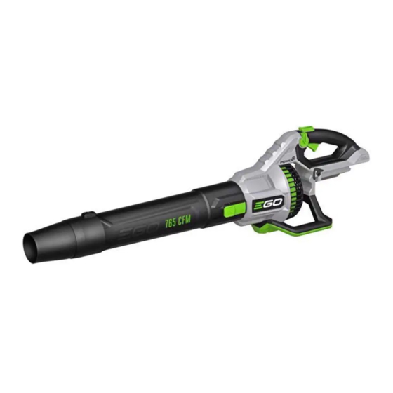
- Page 1 REPAIR GUIDELINE Blower_LB7650 Update Date: 2021/12/29...
-
Page 2: Table Of Contents
Table of Contents Contents Page Troubleshooting Tool list How to Disassemble the Blower 5-11 How to Detect the PCBA and the Motor 12-18 How to Replace the PCBA 19-37 How to Replace the Duct Set (Motor included) 38-43 How to Assemble the Blower 44-46... -
Page 3: Troubleshooting
Troubleshooting Problem Possible Cause Fault Position Test & Solution Handle housing Replace PCBA in the handle. PCBA is damaged. Measure the resistance between any two of the three cable terminals of the duct set using a Multimeter. If the resistance is infinite, the motor is Fail to start open circuit, replace with a new duct Motor is damaged. -
Page 4: Tool List
Tool List For Repair Tool List SPEC Remark Phillips screwdriver Torx screwdriver T10, T15 Heat gun Heat-shrinkable sleeves Scissors To remove the shrinkable sleeve Multi-meter... -
Page 5: How To Disassemble The Blower
How to Disassemble the Blower 1. Remove the 4 screws on the blower bottom base to remove the bottom base. Bottom base... - Page 6 How to Disassemble the Blower 2. Remove the 11 screws to open the blower housings to expose the PCBA and Duct set connectors. Loose this screw with a T-10 bit...
- Page 7 How to Disassemble the Blower 3. Remove the fan baffle away from the housing. If the fan baffle is worn, replace it. Otherwise save it for reassembly. Fan Baffle...
- Page 8 How to Disassemble the Blower The following parts can be replaced after opening the housings. Spring 1 PCBA ASSY Battery Release Button Spring 2 Latch Spring 3 Sliding Block Duct Set Fan Baffle (Motor included)
- Page 9 How to Disassemble the Blower 4. Loosen the 2 screws to remove the speed-adjustment PCBA.
- Page 10 How to Disassemble the Blower 5. Take out the PCBA ASSY from the handle housing. PCBA ASSY Connectors between the These two parts won’t appear PCBA and the duct set in the mass production product. Just ignore.
- Page 11 How to Disassemble the Blower 6. Use scissors to cut off the heat-shrinkable sleeves and remove the transparent sleeves aside to separate the three connectors between the PCBA ASSY and the duct set (motor included). Heat-shrinkable sleeves Transparent sleeve Connectors disconnected...
-
Page 12: How To Detect The Pcba And The Motor
How to Detect the PCBA and the Motor 1. Test the duct set (motor included) to judge if the motor is open-circuit. NOTICE: Judge if there is any burning smell of the motor before having diagnosis. If yes, the motor is burned. Replace it. Otherwise, go on below detection. a) Set the Multimeter function to “Resistance measuring”... - Page 13 How to Detect the PCBA and the Motor 2. Test the PCBA to judge if it is broken. ① Discharge the capacitor that is connected in the PCBA Press down the main switch and then measure a) Multimeter can be used for discharging. the two terminals of the battery electric contacts With the Multimeter function set to “Ω”,...
- Page 14 How to Detect the PCBA and the Motor ② Measure the fuse in the PCBA. a) With the Multimeter function set to “Ω”, pierce one pen pin into the sealing glue and force the pin contacting onto one end of the fuse, then pierce the other pen pin into the sealing glue and contacting onto the other end of the fuse.
- Page 15 How to Detect the PCBA and the Motor ③ Measure the MOSFET in the PCBA (Step 1) a) Set the Multimeter function to “Diode measuring”. b) Contact the red pen pin to the negative electric contact (the battery electric contact that connects to black wire).
- Page 16 How to Detect the PCBA and the Motor Figure showing how to measure the MOSFET in the PCBA (Step 1) Three contactors Negative electric contact Black wire...
- Page 17 How to Detect the PCBA and the Motor ④ Measure the MOSFET in the PCBA (Step 2) a) Keep the Multimeter function setting at “Diode measuring”. b) Contact the black pen pin to the positive electric contact (the battery electric contact that connects to red wire).
- Page 18 How to Detect the PCBA and the Motor Figure showing how to measure the MOSFET in the PCBA (Step 2) Three contactors Positive electric contact Red wire...
-
Page 19: How To Replace The Pcba
How to Replace the PCBA 1. Follow the section “How to Disassemble the Blower” to open the handle housings and separate the connectors between the PCBA and the duct set to remove the PCBA. 2. Save all of the small parts except the PCBA for reassembly. If any of them needs replacement, replace it (Fig. - Page 20 How to Replace the PCBA Spring 2# Battery-release button Latch Sliding Block Spring 3#...
- Page 21 How to Replace the PCBA 3. Reconnect the three connectors between the new PCBA and duct set as below instructed. Correct Connection: Brown to brown, yellow to yellow, blue to blue...
- Page 22 How to Replace the PCBA 4. Test the blower a) Connect the battery electric contact Main Switch of the new PCBA to a fully charged EGO battery. b) Press the main switch briefly and EGO Battery release it. Check the motor(inside the duct set) working status through the fan baffle.
- Page 23 How to Replace the PCBA 5. Align the black cable into the groove at the second edge of the PCBA. Black Cable...
- Page 24 How to Replace the PCBA 6. Firmly holding the black cable in place, and mount the PCBA ASSY into the groove in the left housing. PCBA ASSY...
- Page 25 How to Replace the PCBA 7. Mount the speed-adjustment knob into its corresponding hole in the left housing. Speed-adjustment knob Hole...
- Page 26 How to Replace the PCBA 8. Tighten the speed-adjustment PCBA with the 2 screws. Speed-adjustment PCBA...
- Page 27 How to Replace the PCBA 9. Align the single GREEN cable into the groove. 10. Place the boost switch into the housing groove. Single green cable Boost switch...
- Page 28 How to Replace the PCBA 11. Align the flat cables into the groove.
- Page 29 How to Replace the PCBA 12. Align the other cables which link the main switch to the speed-adjustment PCBA into the groove first and then mount the main switch into the housing groove. Main Switch...
- Page 30 How to Replace the PCBA 13. Align the black cable into the groove. 14. Place the capacitor into the housing groove. Capacitor...
- Page 31 How to Replace the PCBA 15. Mount the battery electric contacts into the left housing and align the cables into the groove. This part won’t appear in the mass production Battery electric contacts product. Just ignore.
- Page 32 How to Replace the PCBA 16. Add some waterproof glue on position1 and position2 to protect the electric circuit board and positon3. Position1 Position3 Position2...
- Page 33 How to Replace the PCBA 17. Place one spring 1# onto the turbo trigger first. 18. Align the hole on the turbo trigger with the rib on the left housing, then mount the trigger onto the rib. Turbo trigger Hole Spring 1#...
- Page 34 How to Replace the PCBA 19. Assemble the other spring 1# onto the main trigger. 20. Align the rib on the main trigger with the hole on the left housing to mount the main trigger into its place. Spring 1# Main trigger Hole...
- Page 35 How to Replace the PCBA 21. Mount the sliding block with the battery electric contacts and place the sliding block with the spring 3# into the groove of the left housing. Battery Electric contacts Sliding Block Spring 3#...
- Page 36 How to Replace the PCBA 22. Assemble the battery-release button, latch and spring 2# first, and then mount them into the groove of the left housing. Spring 2# Battery-release button Latch...
- Page 37 How to Replace the PCBA 23. Connect the connectors between the PCBA and the duct set.
-
Page 38: How To Replace The Duct Set (Motor Included)
How to Replace the Duct Set (Motor included) 1. Follow the section “How to Disassemble the Blower” to open the handle housings and separate the connectors between the PCBA and the duct set to remove the duct set. 2. Replace with a new duct set. Duct set... - Page 39 How to Replace the Duct Set (Motor included) 3. Put on 3 new heat-shrinkable sleeves one by one onto each terminal, move the transparent sleeve aside before connecting the 3 connectors and then cover the connectors with the transparent sleeves. Correct Connection: Brown to brown, yellow to yellow, blue to blue...
- Page 40 How to Replace the Duct Set (Motor included) 4. Cover the 3 connectors with the heat-shrinkable sleeves and use the heat gun to shrink them. 5. Align the connectors into the corresponding groove in the left housing.
- Page 41 6. Test the blower a) Connect the battery electric Look through the fan baffle and contact of the PCBA to a fully check the fan rotation direction charged EGO battery. b) Press the main switch briefly and release it. c) Check the motor(inside the duct set) working status through the fan baffle .
- Page 42 How to Replace the Duct Set (Motor included) 7. Check to make sure the two rubber gaskets are located into the left handle housing. If they fell out during disassembly, re-place them. 8. Align the knobs on the duct set with the rubber gasket holes in the left handle housing and mount the duct set in the left housing.
- Page 43 How to Replace the Duct Set (Motor included) 9. Align the wires into the grooves. Connectors stored here Align the wires into the groove...
-
Page 44: How To Assemble The Blower
How to Assemble the Blower 1. Before closing the right housing, make sure another two rubber gaskets are located into the right housing, if they fell out during disassembly, re-place them. Rubber Gasket... - Page 45 How to Assemble the Blower 2. Align the rib on the fan baffle with the limit slot in handle housing, and mount the fan baffle into the outside groove in the left housing. Limit slot for fan baffle rib Rib on the Fan Baffle Limit slot for fan baffle rib...
- Page 46 How to Assemble the Blower 3. Check to make sure all the components are fixed in position, and wires are well aligned, then tighten the 11 screws to tighten the handle housings. 4. Install a fully charged battery onto the blower and test the blower. Fasten this screw with a T-10 bit THE END...
Need help?
Do you have a question about the LB7650 and is the answer not in the manual?
Questions and answers
where is the fuse located on the 765cfm unit
The fuse is located at the end of the fuse on the PCBA (Printed Circuit Board Assembly) inside the EGO LB7650 unit.
This answer is automatically generated
How do I receive warranty when the item is 8 months old and does not run anymore