Table of Contents
Advertisement
Quick Links
INSTALLATION MANUAL
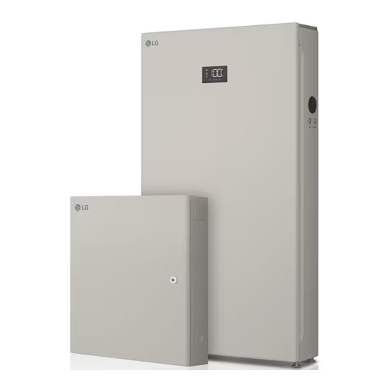
Energy Storage System
Please read this manual carefully before operating and retain it for future reference.
Model
LG Electronics ESS Home 5 (RBA005K0A0F)
Home 5 (RA500K16A11)
Smart Energy Box (REA200AP0)
* M F L 7 1 8 9 3 1 0 1 *
R e v . H 1 7 / 0 4 / 2 0 2 4
©LG Electronics U.S.A., Inc., Englewood Cliffs, NJ. All rights reserved. "LG" is a registered trademark of LG Corp.
Due to our policy of continuous product innovation, some specifications may change without notice.
LG Electronics ESS Home 8 (RBA008K0A00)
Home 8 (RA768K16A11)
Smart Energy Box (REA200AP0)
Copyright © 2022 - 2024 LGEUS All Rights Reserved.
http://www.lg.com/us/ess
Advertisement
Table of Contents

Subscribe to Our Youtube Channel
Related Manuals for LG Home 5


Summary of Contents for LG Home 5
- Page 1 Copyright © 2022 - 2024 LGEUS All Rights Reserved. Due to our policy of continuous product innovation, some specifications may change without notice. ©LG Electronics U.S.A., Inc., Englewood Cliffs, NJ. All rights reserved. “LG” is a registered trademark of LG Corp.
- Page 2 For continual product development, LG Electronics U.S.A., Inc. reserves the right to change specifications without notice. © LG Electronics U.S.A., Inc. Due to our policy of continuous product innovation, some specifications may change without notice. ©LG Electronics U.S.A., Inc., Englewood Cliffs, NJ. All rights reserved. “LG” is a registered trademark of LG Corp.
-
Page 3: Important Safety Instructions
LG disclaims any and all liability arising out of any such use of the system. Further, LG reserves the right to refuse to service any system used for these purposes and disclaims any and all liability arising out of LG’ s service or refusal to service systems in such circumstances. - Page 4 Do not open or assemble while product is working. Due to our policy of continuous product innovation, some specifications may change without notice. ©LG Electronics U.S.A., Inc., Englewood Cliffs, NJ. All rights reserved. “LG” is a registered trademark of LG Corp.
- Page 5 To reduce the risk of fire, do not connect to an AC load center (circuit breaker panel) with multiwire branch circuits connected. Due to our policy of continuous product innovation, some specifications may change without notice. ©LG Electronics U.S.A., Inc., Englewood Cliffs, NJ. All rights reserved. “LG” is a registered trademark of LG Corp.
- Page 6 Smart Energy Box (SE Box) display and follow the solution described in the manual. Due to our policy of continuous product innovation, some specifications may change without notice. ©LG Electronics U.S.A., Inc., Englewood Cliffs, NJ. All rights reserved. “LG” is a registered trademark of LG Corp.
- Page 7 INFO Indicates a risk of possible damage to the product. y The System consists of Home 5/8 and SE Box. They must be installed together and it will not work when installing unauthorized components to the system. y The unit is designed to feed power to the public grid only. Do not connect the unit to a generator as connecting the power to external devices could result in serious damage to the equipment.
-
Page 8: First Aid Measures
- Do not use the submerged battery again. Contact your service engineer for assistance. Due to our policy of continuous product innovation, some specifications may change without notice. ©LG Electronics U.S.A., Inc., Englewood Cliffs, NJ. All rights reserved. “LG” is a registered trademark of LG Corp. -
Page 9: Table Of Contents
Wiring Connection between the SE Box and Home 5/8 ....... . - Page 10 Multiple Home 5/8 Units or PV Inverters Connection ....... . .
-
Page 11: Product Features
1) PV inverter is NOT PROVIDED by LG Electronics. y All In One ESS LG Electronics ESS Home 5/8 is a product designed to integrate a grid-connected inverter and battery in one enclosure. This product is an AC-Coupled type and is directly connected to the household power grid. - Page 12 5/8. For these functions, “Backup” should be enabled in the system. y System Scalability Up to 4 Home 5/8 units can be connected to one SE Box. (The required number of Home 5/8 may vary depending on the electric service capacity, the load consumption characteristic, and the preferred operation of the home.
- Page 13 Observe precautions for handling electrostatic discharge sensitive devices. Due to our policy of continuous product innovation, some specifications may change without notice. ©LG Electronics U.S.A., Inc., Englewood Cliffs, NJ. All rights reserved. “LG” is a registered trademark of LG Corp.
- Page 14 The current charge level of a rechargeable battery relative to its capacity. Due to our policy of continuous product innovation, some specifications may change without notice. ©LG Electronics U.S.A., Inc., Englewood Cliffs, NJ. All rights reserved. “LG” is a registered trademark of LG Corp.
- Page 15 A set of rules for sending data across a network. Due to our policy of continuous product innovation, some specifications may change without notice. ©LG Electronics U.S.A., Inc., Englewood Cliffs, NJ. All rights reserved. “LG” is a registered trademark of LG Corp.
-
Page 16: Unpacking
Pull out the SE Box from the package. Due to our policy of continuous product innovation, some specifications may change without notice. ©LG Electronics U.S.A., Inc., Englewood Cliffs, NJ. All rights reserved. “LG” is a registered trademark of LG Corp. -
Page 17: Unpacking The Home 5/8
When moving the product using a lift, secure the product using a belt, etc. INFO Be careful not to damage Home 5/8 when standing the product on the hand lift. The cut-out part at the bottom of the box can be used to prevent scratches by inserting it between the product and the hand lift. - Page 18 Home 5/8 upright on the hand lift. Due to our policy of continuous product innovation, some specifications may change without notice. ©LG Electronics U.S.A., Inc., Englewood Cliffs, NJ. All rights reserved. “LG” is a registered trademark of LG Corp.
- Page 19 N-GND bonding busbar O rings (4EA) CT terminal block (2EA) Due to our policy of continuous product innovation, some specifications may change without notice. ©LG Electronics U.S.A., Inc., Englewood Cliffs, NJ. All rights reserved. “LG” is a registered trademark of LG Corp.
- Page 20 Due to our policy of continuous product innovation, some specifications may change without notice. ©LG Electronics U.S.A., Inc., Englewood Cliffs, NJ. All rights reserved. “LG” is a registered trademark of LG Corp.
- Page 21 - Main Breaker : CSR2100, CSR2125N, CSR2150N, CSR2175N, CSR2200N, BW2100, BW2125, BW215N, BW2175 or BW2200 from Eaton - Branch Breaker for Home 5/8 and PV inverter connection : Eaton BR series should be used for the internal panelboard. - Hold Down Kit for fixing BR series circuit breaker : BRHDK125...
-
Page 22: Part Names
(Momentary type, press and hold for 6 seconds) Due to our policy of continuous product innovation, some specifications may change without notice. ©LG Electronics U.S.A., Inc., Englewood Cliffs, NJ. All rights reserved. “LG” is a registered trademark of LG Corp. -
Page 23: Connection Parts (Home 5/8)
WARNING The battery packs and harness contain high voltages. Risk of death or serious injury due to electric shock. Before working on any Home 5/8 wiring, make sure the Home 5/8 battery circuit breaker is set to OFF. DIP switches... -
Page 24: Led Indications (Home 5/8)
Discharge BAT. Discharging Not operating Fault Fault Normal Due to our policy of continuous product innovation, some specifications may change without notice. ©LG Electronics U.S.A., Inc., Englewood Cliffs, NJ. All rights reserved. “LG” is a registered trademark of LG Corp. -
Page 25: Front And Rear (Se Box)
Conduit knockout (right) Conduit knockouts (bottom) Conduit hole (bottom) Due to our policy of continuous product innovation, some specifications may change without notice. ©LG Electronics U.S.A., Inc., Englewood Cliffs, NJ. All rights reserved. “LG” is a registered trademark of LG Corp. -
Page 26: Connection Parts (Se Box)
Ground terminals for Home 5/8 and PV inverter Grid terminal (L2) Due to our policy of continuous product innovation, some specifications may change without notice. ©LG Electronics U.S.A., Inc., Englewood Cliffs, NJ. All rights reserved. “LG” is a registered trademark of LG Corp. -
Page 27: Installation
Choose a leveled floor and wall capable of supporting the full weight of the Home 5/8 and SE box. y Prepare appropriate screws, anchors, and additional supports for the wall type. -
Page 28: Installation Location
Before installing the product, select an appropriate installation location for the safe use of the product. The Home 5/8 and SE Box has been certified NEMA 3R and can be installed indoors as well as outdoors. However, if installed outdoors, do not allow the product to be exposed to water sources or continuously exposed to sunlight or other conditions that result in a consistent operating temperature below -10˚C... - Page 29 Install this product out of reach of children and pets. Due to our policy of continuous product innovation, some specifications may change without notice. ©LG Electronics U.S.A., Inc., Englewood Cliffs, NJ. All rights reserved. “LG” is a registered trademark of LG Corp.
- Page 30 Due to our policy of continuous product innovation, some specifications may change without notice. ©LG Electronics U.S.A., Inc., Englewood Cliffs, NJ. All rights reserved. “LG” is a registered trademark of LG Corp.
-
Page 31: Minimum Clearance
Ensure that the distance between the wall and Home 5/8 is at least 25 mm (1 inch). Be sure not to place any object on top of the Home 5/8 to prevent risk of fire or serious injury due to high temperature. - Page 32 Due to our policy of continuous product innovation, some specifications may change without notice. ©LG Electronics U.S.A., Inc., Englewood Cliffs, NJ. All rights reserved. “LG” is a registered trademark of LG Corp.
-
Page 33: Floor Standing Wall Support
Make sure the pilot hole size matches the anchor type. y The weight of the Home 5/8 is 163kg (359 lbs), and the SE Box is 25 kg (55 lbs). The wall must contain blocked studs that can bear the weight and are of masonry or other suitable structures. - Page 34 Align the upper and lower brackets so that they are straight vertically. Due to our policy of continuous product innovation, some specifications may change without notice. ©LG Electronics U.S.A., Inc., Englewood Cliffs, NJ. All rights reserved. “LG” is a registered trademark of LG Corp.
- Page 35 CAUTION y The Home 5/8 is very heavy. Serious injury may occur due to the heavy weight when mounting it to the wall. Therefore, special care must be taken in handling. Make sure to use the lift instead of using human strength when installing.
- Page 36 Installation WARNING y Before making a connection to the Home 5/8, make sure that the battery circuit breaker is OFF. If the circuit breaker is ON, death or serious injury may occur due to electric shock. y High voltage is energized through the internal battery module and wiring. Special care must be taken when working on a Home 5/8 connection.
- Page 37 63 mm (2.5 inches) Concrete fasteners with washers Due to our policy of continuous product innovation, some specifications may change without notice. ©LG Electronics U.S.A., Inc., Englewood Cliffs, NJ. All rights reserved. “LG” is a registered trademark of LG Corp.
-
Page 38: Mounting The Se Box
It may cause the lock to break. Due to our policy of continuous product innovation, some specifications may change without notice. ©LG Electronics U.S.A., Inc., Englewood Cliffs, NJ. All rights reserved. “LG” is a registered trademark of LG Corp. - Page 39 Be careful not to be injured by the sharp edge when make the conduit hole or connecting a conduit. Due to our policy of continuous product innovation, some specifications may change without notice. ©LG Electronics U.S.A., Inc., Englewood Cliffs, NJ. All rights reserved. “LG” is a registered trademark of LG Corp.
- Page 40 76 mm (3 inch) in length and have a head diameter of more than 16mm (0.63 inch). Due to our policy of continuous product innovation, some specifications may change without notice. ©LG Electronics U.S.A., Inc., Englewood Cliffs, NJ. All rights reserved. “LG” is a registered trademark of LG Corp.
-
Page 41: Connections
SE Box Main panel with main breaker (Backup) Due to our policy of continuous product innovation, some specifications may change without notice. ©LG Electronics U.S.A., Inc., Englewood Cliffs, NJ. All rights reserved. “LG” is a registered trademark of LG Corp. -
Page 42: Service Equipment Preparation (If Required)
Connection of the earth rod must comply with local regulations. Due to our policy of continuous product innovation, some specifications may change without notice. ©LG Electronics U.S.A., Inc., Englewood Cliffs, NJ. All rights reserved. “LG” is a registered trademark of LG Corp. - Page 43 Eaton® CSR or BW type breakers can be used. Refer to "Compatible Eaton Parts" for breaker types and required accessories. Due to our policy of continuous product innovation, some specifications may change without notice. ©LG Electronics U.S.A., Inc., Englewood Cliffs, NJ. All rights reserved. “LG” is a registered trademark of LG Corp.
- Page 44 Home 5/8 units and PV inverters. It is recommended that the terminal of the lug block should head to the right in consideration of wire bending space.
-
Page 45: Wiring Connection Between The Se Box And Home 5/8
Installation Wiring Connection between the SE Box and Home 5/8 This is an example of 1 Home 5/8 connection. For multiple Home 5/8 connections, please refer to "Multiple Home 5/8 Units or PV Inverters Connection". WARNING y The system wiring must follow ANSI/NFPA 70 and other local codes. - Page 46 Installation WARNING y Before making a connection to the Home 5/8, make sure that the battery circuit breaker is OFF. If the circuit breaker is ON, death or serious injury may occur due to electric shock. y High voltage is energized through the internal battery module and wiring. Special care must be taken when working on a Home 5/8 connection.
- Page 47 L2 (Red) N (White) G (Green) Com. (Gray) Strip off the AC power conductors (L1, L2, Neutral, and Ground) on both the Home 5/8 and SE Box sides as shown in the figure below. 6-4 AWG 18 mm (0.7 inch) 8-6 AWG 13 mm (0.5 inch)
- Page 48 On the Home 5/8 side, connect the AC conductors to the corresponding terminals as shown in the figure below. There are two ground terminals on the Home 5/8 side. Connect the AC power ground to the upper ground terminal. The ground terminals are identified with the following symbol:...
- Page 49 50 mm (2 inches) 8 mm (0.3 inch) Due to our policy of continuous product innovation, some specifications may change without notice. ©LG Electronics U.S.A., Inc., Englewood Cliffs, NJ. All rights reserved. “LG” is a registered trademark of LG Corp.
- Page 50 Set the terminating resistor for CAN communication by using a DIP switch. When multiple Home 5/8 units are installed, this terminating resistor should be ON in the last Home 5/8 in the daisy chain. Refer to "Multiple Connection ID Setup Method" for more information.
- Page 51 Shake the cable to check the connection status. Due to our policy of continuous product innovation, some specifications may change without notice. ©LG Electronics U.S.A., Inc., Englewood Cliffs, NJ. All rights reserved. “LG” is a registered trademark of LG Corp.
- Page 52 Fix the cable in the upper hook as shown in the figure. Arrange the cable between the plastic case and metal enclosure. Cut back the drain wire and shield. The drain wire should be terminated at the Home 5/8 chassis ground terminal only.
-
Page 53: Grid And Load Connections
L1 (Black) L2 (Red) N (White) From Grid Due to our policy of continuous product innovation, some specifications may change without notice. ©LG Electronics U.S.A., Inc., Englewood Cliffs, NJ. All rights reserved. “LG” is a registered trademark of LG Corp. - Page 54 SE Box Button Hole Inner 1 ½ inches Outer 2 inches Due to our policy of continuous product innovation, some specifications may change without notice. ©LG Electronics U.S.A., Inc., Englewood Cliffs, NJ. All rights reserved. “LG” is a registered trademark of LG Corp.
- Page 55 Due to our policy of continuous product innovation, some specifications may change without notice. ©LG Electronics U.S.A., Inc., Englewood Cliffs, NJ. All rights reserved. “LG” is a registered trademark of LG Corp.
- Page 56 Refer to "Whole Home Backup (Service Equipment)" for example system wiring diagrams. Due to our policy of continuous product innovation, some specifications may change without notice. ©LG Electronics U.S.A., Inc., Englewood Cliffs, NJ. All rights reserved. “LG” is a registered trademark of LG Corp.
-
Page 57: Connect To Pv Inverter
Installation Connect to PV Inverter This is an example of a 1 PV inverter connection. For multiple Home 5/8 connections, please refer to "Multiple Home 5/8 Units or PV Inverters Connection". INFO y PV inverters must support a Frequency-Drop or Frequency-Watt functions. - Page 58 Make sure the CTs are facing the proper direction as described in this manual. A CT will show a negative current if installed in reverse. Due to our policy of continuous product innovation, some specifications may change without notice. ©LG Electronics U.S.A., Inc., Englewood Cliffs, NJ. All rights reserved. “LG” is a registered trademark of LG Corp.
- Page 59 Fix the cable in the hook as shown in the figure below. Due to our policy of continuous product innovation, some specifications may change without notice. ©LG Electronics U.S.A., Inc., Englewood Cliffs, NJ. All rights reserved. “LG” is a registered trademark of LG Corp.
- Page 60 Refer to "SE Box Wiring: Current Transformer (CT)" for CT configuration troubleshooting tips. Due to our policy of continuous product innovation, some specifications may change without notice. ©LG Electronics U.S.A., Inc., Englewood Cliffs, NJ. All rights reserved. “LG” is a registered trademark of LG Corp.
-
Page 61: Internet Connection
Fix the cable to the lower hook as shown in the figure. Arrange the cable between the plastic case and metal enclosure. Due to our policy of continuous product innovation, some specifications may change without notice. ©LG Electronics U.S.A., Inc., Englewood Cliffs, NJ. All rights reserved. “LG” is a registered trademark of LG Corp. -
Page 62: External Shutdown Switch Installation (If Required)
Before making a connection on the shutdown switch, you must ensure disconnection from the Home 5/8, Grid, and other power sources. It may cause death or serious injury due to electric shock. y Conduit fittings (hubs) are required for all installations. NEMA Type 3R conduit fittings (hubs) are required when installing outdoors. - Page 63 Installation Confirm that all Home 5/8 operation is shut down when the switch is pressed with a plunger type switch or OFF position with the rotary type switch. External Shutdown Switch Requirements y The External Shutdown Switch is supported on firmware version 1.0.2641 or later.
- Page 64 When Black Start operation is required, follow the guidelines for "Black Start". Due to our policy of continuous product innovation, some specifications may change without notice. ©LG Electronics U.S.A., Inc., Englewood Cliffs, NJ. All rights reserved. “LG” is a registered trademark of LG Corp.
-
Page 65: Backup Load Connection
After the installation, please check whether the LG Electronics ESS Home 5/8 can provide backup power properly in "Backup Testing Guidelines". - The backup load will be supplied by the LG Electronics ESS Home 5/8 and PV during a power outage. - The non-backup load will power down during a power outage. -
Page 66: Backup Testing Guidelines
* LG Electronics ESS Home 5/8 provides the seamless transition within 100ms. Run the LG Electronics ESS Home 5/8 and make sure the system is operating and not set to “STOP” To prevent a system malfunction caused by the backup operation, please leave the PV circuit breaker in the OFF position during this step. - Page 67 If the system cannot operate normally without using the air conditioner or pumps during the backup test, 1. Check the load consumption power in backup and check the ambient temperature around the Home 5/8 unit. The output power may be de-rated by the temperature to protect the battery units. If the total load consumed power is over the available maximum discharging power, large loads may also need to be move to non-backup panel.
-
Page 68: Installation Completion
Installation Installation Completion Before closing any installed hardware, take photos of the completed wiring in the SE Box, Home 5/8, and main panel. Make sure that all conduit junctions and cable entry points are secure and properly sealed. Arrange the communication and AC power wires neatly inside the Home 5/8 wiring compartment. - Page 69 High voltage is energized through the internal battery module and wiring. Special care must be taken. Switch the battery circuit breaker on the Home 5/8 to the ON position and close the front cover. When closing the cabinet door, make sure the front cover is securely fitted to the gasket for a proper waterproof seal.
- Page 70 Make sure to push the door to align the screw holes when fastening the screws. Fasten the screws on the right side of the Home 5/8. (25 kgf·cm (22 lbf·in) torque, Hex socket : M8) INFO The main circuit breaker for the SE Box should be installed in the SE Box or upstream of the SE Box.
- Page 71 Press the POWER button and press and hold the BLACK START (6s) button for at least 6 seconds until you hear a "click." If the SoC level is shown on the LED display of the Home 5/8, the booting process has been completed normally.
- Page 72 Set all of the system settings on the HMI display of the SE Box and start commissioning. Due to our policy of continuous product innovation, some specifications may change without notice. ©LG Electronics U.S.A., Inc., Englewood Cliffs, NJ. All rights reserved. “LG” is a registered trademark of LG Corp.
-
Page 73: Wiring Reference
Suitable wire ferrules may be used for power terminals, but are not required. Due to our policy of continuous product innovation, some specifications may change without notice. ©LG Electronics U.S.A., Inc., Englewood Cliffs, NJ. All rights reserved. “LG” is a registered trademark of LG Corp. - Page 74 * Use copper or aluminum conductors rated at 90 °C (194 °F). Due to our policy of continuous product innovation, some specifications may change without notice. ©LG Electronics U.S.A., Inc., Englewood Cliffs, NJ. All rights reserved. “LG” is a registered trademark of LG Corp.
- Page 75 (Eaton BRPSF225) on the internal panel board. In this case, other spaces on the internal panelboard can not be used for the circuit breaker. Leave no breakers. The Home 5/8 connection to the SE Box always requires a 40 A Circuit breaker. This breaker serves as circuit protection for the Home 5/8.
- Page 76 Blue (CAT 5E STP) 24 – 16 AWG Due to our policy of continuous product innovation, some specifications may change without notice. ©LG Electronics U.S.A., Inc., Englewood Cliffs, NJ. All rights reserved. “LG” is a registered trademark of LG Corp.
- Page 77 Twisted cable may improve the CT measuring. If an extended cable is required, please twist. Due to our policy of continuous product innovation, some specifications may change without notice. ©LG Electronics U.S.A., Inc., Englewood Cliffs, NJ. All rights reserved. “LG” is a registered trademark of LG Corp.
- Page 78 - Do not simply twist the bare wires together. Due to our policy of continuous product innovation, some specifications may change without notice. ©LG Electronics U.S.A., Inc., Englewood Cliffs, NJ. All rights reserved. “LG” is a registered trademark of LG Corp.
-
Page 79: Installer Setup Wizard
[Language]: Press the currently selected language and select the desired language to change. Due to our policy of continuous product innovation, some specifications may change without notice. ©LG Electronics U.S.A., Inc., Englewood Cliffs, NJ. All rights reserved. “LG” is a registered trademark of LG Corp. - Page 80 If the system is not connected to the internet, the installer cannot monitor the system status through the web monitoring system or mobile app. Due to our policy of continuous product innovation, some specifications may change without notice. ©LG Electronics U.S.A., Inc., Englewood Cliffs, NJ. All rights reserved. “LG” is a registered trademark of LG Corp.
- Page 81 Step 4: System Information You can check the system information. Check that the loaded system information is correct. If it is not, check the DIP switches on each Home 5/8 and press [Rescan] to retrieve the information. Refer to step 9 of the "Wiring Connection between the SE Box and Home 5/8" for DIP switch settings.
- Page 82 Settings You can check the information of the installed ESS on the system information screen. If Home 8 is connected to SEBox, ESS mode name is displayed “RA768K16A11” . If Home 5 is connected, it is displayed “RA500K16A11” When next step button is pressed, If the ESS information detected at the initial booting is different from the current information, reboot and refresh the initial information.
- Page 83 You can set the current date and time. Refer to "Date & Time Settings" for more information. Due to our policy of continuous product innovation, some specifications may change without notice. ©LG Electronics U.S.A., Inc., Englewood Cliffs, NJ. All rights reserved. “LG” is a registered trademark of LG Corp.
- Page 84 Select the appropriate grid profile option for the system environment. Select the grid profile at your location. Due to our policy of continuous product innovation, some specifications may change without notice. ©LG Electronics U.S.A., Inc., Englewood Cliffs, NJ. All rights reserved. “LG” is a registered trademark of LG Corp.
- Page 85 Trip Time Range 0.16 0.16 1000 0.16 0.16 1000 Due to our policy of continuous product innovation, some specifications may change without notice. ©LG Electronics U.S.A., Inc., Englewood Cliffs, NJ. All rights reserved. “LG” is a registered trademark of LG Corp.
- Page 86 If you are using a PV inverter, set this option to [Use] and fill the [PV Rate Output Power] and [Installed PV Panel Capacity] fields. Due to our policy of continuous product innovation, some specifications may change without notice. ©LG Electronics U.S.A., Inc., Englewood Cliffs, NJ. All rights reserved. “LG” is a registered trademark of LG Corp.
- Page 87 You can check the device that are connected to port 1 and port 2. If no devices are connected to the ports, it will display as [None]. Due to our policy of continuous product innovation, some specifications may change without notice. ©LG Electronics U.S.A., Inc., Englewood Cliffs, NJ. All rights reserved. “LG” is a registered trademark of LG Corp.
- Page 88 Backup Operation, the Reserve SoC is set to 0%. Due to our policy of continuous product innovation, some specifications may change without notice. ©LG Electronics U.S.A., Inc., Englewood Cliffs, NJ. All rights reserved. “LG” is a registered trademark of LG Corp.
- Page 89 This should be checked in the PCS manual(Appendix). (Relay Box too) Due to our policy of continuous product innovation, some specifications may change without notice. ©LG Electronics U.S.A., Inc., Englewood Cliffs, NJ. All rights reserved. “LG” is a registered trademark of LG Corp.
- Page 90 If it is not possible to run a [Commissioning Test], select [Start System] to launch the system. Due to our policy of continuous product innovation, some specifications may change without notice. ©LG Electronics U.S.A., Inc., Englewood Cliffs, NJ. All rights reserved. “LG” is a registered trademark of LG Corp.
-
Page 91: About The Home Screen
You can check the power flow and error messages for the PV, Battery, Grid, and Home load. If there are 2 or more Home 5/8 units installed in the system, each Home 5/8's status and error messages are displayed on the HOME screen as shown below. - Page 92 Settings Errors If an error occurs in the SE Box or Home 5/8, the current error information is displayed in the Event History. Press to show the errors. [Type] shows the severity of the error, [Device] shows the information of the device where the error occurred, and [Code] shows the error code.
-
Page 93: Installer And User Settings
If you input the incorrect password 5 times, you cannot attempt to input another password for one minute. Due to our policy of continuous product innovation, some specifications may change without notice. ©LG Electronics U.S.A., Inc., Englewood Cliffs, NJ. All rights reserved. “LG” is a registered trademark of LG Corp. -
Page 94: General Settings
Press the currently selected language and select the desired language to change. Due to our policy of continuous product innovation, some specifications may change without notice. ©LG Electronics U.S.A., Inc., Englewood Cliffs, NJ. All rights reserved. “LG” is a registered trademark of LG Corp. - Page 95 Address] and [DNS Address] options manually and press [Apply] to apply the network settings. Due to our policy of continuous product innovation, some specifications may change without notice. ©LG Electronics U.S.A., Inc., Englewood Cliffs, NJ. All rights reserved. “LG” is a registered trademark of LG Corp.
- Page 96 If the signal is not strong enough to connect the internet, please consider installing the LG SE Box as close as possible to the router or install a WiFi range extender or Signal Booster.
- Page 97 SE Box and access point, and the location of the SE Box. Due to our policy of continuous product innovation, some specifications may change without notice. ©LG Electronics U.S.A., Inc., Englewood Cliffs, NJ. All rights reserved. “LG” is a registered trademark of LG Corp.
- Page 98 Press [Time format] and select either [12 Hours] or [24 Hours]. Due to our policy of continuous product innovation, some specifications may change without notice. ©LG Electronics U.S.A., Inc., Englewood Cliffs, NJ. All rights reserved. “LG” is a registered trademark of LG Corp.
- Page 99 Press the ON/OFF switch to enable or disable this function. INFO To use the Soft AP function, you need to register your system through the LG ThinQ® App. Refer to the LG ThinQ® App guide for detailed information. Open Source Press [Open Source] to see the Open Source Software Notice.
- Page 100 Press [Factory Reset] and select [Reset] in the pop-up to reset all of the settings to factory default. Due to our policy of continuous product innovation, some specifications may change without notice. ©LG Electronics U.S.A., Inc., Englewood Cliffs, NJ. All rights reserved. “LG” is a registered trademark of LG Corp.
-
Page 101: Pcs Settings
You can check the information of the installed ESS on the system information screen. If Home 8 is connected to SEBox, ESS mode name is displayed “RA768K16A11” . If Home 5 is connected, it is displayed “RA500K16A11”... - Page 102 Press [PCS Settings] > [System Name] to set a system name. Due to our policy of continuous product innovation, some specifications may change without notice. ©LG Electronics U.S.A., Inc., Englewood Cliffs, NJ. All rights reserved. “LG” is a registered trademark of LG Corp.
- Page 103 Select the appropriate grid profile option for the system environment. Select the grid profile at your location. Due to our policy of continuous product innovation, some specifications may change without notice. ©LG Electronics U.S.A., Inc., Englewood Cliffs, NJ. All rights reserved. “LG” is a registered trademark of LG Corp.
- Page 104 Trip Time Range 0.16 0.16 1000 0.16 0.16 1000 Due to our policy of continuous product innovation, some specifications may change without notice. ©LG Electronics U.S.A., Inc., Englewood Cliffs, NJ. All rights reserved. “LG” is a registered trademark of LG Corp.
- Page 105 If the port setting is set to [Modbus], set the detailed settings such as [Slave ID], [Baud rate], [Start Bit], [Parity], and [Stop Bit]. Due to our policy of continuous product innovation, some specifications may change without notice. ©LG Electronics U.S.A., Inc., Englewood Cliffs, NJ. All rights reserved. “LG” is a registered trademark of LG Corp.
- Page 106 Due to our policy of continuous product innovation, some specifications may change without notice. ©LG Electronics U.S.A., Inc., Englewood Cliffs, NJ. All rights reserved. “LG” is a registered trademark of LG Corp.
- Page 107 You can set the battery's reserve SoC level in case of a power outage. The default level is set to 20%. Due to our policy of continuous product innovation, some specifications may change without notice. ©LG Electronics U.S.A., Inc., Englewood Cliffs, NJ. All rights reserved. “LG” is a registered trademark of LG Corp.
- Page 108 For information on an error code, refer to "Error Codes and Messages". Due to our policy of continuous product innovation, some specifications may change without notice. ©LG Electronics U.S.A., Inc., Englewood Cliffs, NJ. All rights reserved. “LG” is a registered trademark of LG Corp.
- Page 109 [Backup] state is [SUCCESS]. Due to our policy of continuous product innovation, some specifications may change without notice. ©LG Electronics U.S.A., Inc., Englewood Cliffs, NJ. All rights reserved. “LG” is a registered trademark of LG Corp.
- Page 110 If more energy security is prefered, keeping the reserved mode SOC higher is recommended. Due to our policy of continuous product innovation, some specifications may change without notice. ©LG Electronics U.S.A., Inc., Englewood Cliffs, NJ. All rights reserved. “LG” is a registered trademark of LG Corp.
- Page 111 It sets the start frequency level to determine when backup mode will operate. Due to our policy of continuous product innovation, some specifications may change without notice. ©LG Electronics U.S.A., Inc., Englewood Cliffs, NJ. All rights reserved. “LG” is a registered trademark of LG Corp.
-
Page 112: Enervu Settings (Installer Only)
Then, fill out all of the other fields. Due to our policy of continuous product innovation, some specifications may change without notice. ©LG Electronics U.S.A., Inc., Englewood Cliffs, NJ. All rights reserved. “LG” is a registered trademark of LG Corp. -
Page 113: Adding A New Installer
Select the [Add New User] button to open a new user input pop-up. Due to our policy of continuous product innovation, some specifications may change without notice. ©LG Electronics U.S.A., Inc., Englewood Cliffs, NJ. All rights reserved. “LG” is a registered trademark of LG Corp. - Page 114 Then, the new installer can sign to EnerVu. Due to our policy of continuous product innovation, some specifications may change without notice. ©LG Electronics U.S.A., Inc., Englewood Cliffs, NJ. All rights reserved. “LG” is a registered trademark of LG Corp.
-
Page 115: Registering The System (Web Browser)
[Save] to save the entries. Select [OK] to go to next step. Due to our policy of continuous product innovation, some specifications may change without notice. ©LG Electronics U.S.A., Inc., Englewood Cliffs, NJ. All rights reserved. “LG” is a registered trademark of LG Corp. - Page 116 Due to our policy of continuous product innovation, some specifications may change without notice. ©LG Electronics U.S.A., Inc., Englewood Cliffs, NJ. All rights reserved. “LG” is a registered trademark of LG Corp.
-
Page 117: Incomplete Registration Status
If the above condition is fulfilled, the installer can then add and monitor the ESS system. Due to our policy of continuous product innovation, some specifications may change without notice. ©LG Electronics U.S.A., Inc., Englewood Cliffs, NJ. All rights reserved. “LG” is a registered trademark of LG Corp. -
Page 118: Using Lg Thinq® Applications (For User)
Follow the instructions to download and install the application. INFO If you choose the simple login method to access the LG ThinQ® application, you must go through the system registration process each time you change your mobile phone or reinstall the application. -
Page 119: Using Lg Thinq
The application is subject to change for appliance improvement purposes without notice. y Functions may vary by model. Due to our policy of continuous product innovation, some specifications may change without notice. ©LG Electronics U.S.A., Inc., Englewood Cliffs, NJ. All rights reserved. “LG” is a registered trademark of LG Corp. - Page 120 LG ThinQ® app with mobile data or cellular data. Due to our policy of continuous product innovation, some specifications may change without notice. ©LG Electronics U.S.A., Inc., Englewood Cliffs, NJ. All rights reserved. “LG” is a registered trademark of LG Corp.
-
Page 121: Troubleshooting
BAT1 State Error Automatically restart after battery state is normal Due to our policy of continuous product innovation, some specifications may change without notice. ©LG Electronics U.S.A., Inc., Englewood Cliffs, NJ. All rights reserved. “LG” is a registered trademark of LG Corp. - Page 122 Automatically restart after Converter bottom temp is normal Due to our policy of continuous product innovation, some specifications may change without notice. ©LG Electronics U.S.A., Inc., Englewood Cliffs, NJ. All rights reserved. “LG” is a registered trademark of LG Corp.
-
Page 123: Se Box Error Code
S205 PV meter is miswired Contact service center Due to our policy of continuous product innovation, some specifications may change without notice. ©LG Electronics U.S.A., Inc., Englewood Cliffs, NJ. All rights reserved. “LG” is a registered trademark of LG Corp. -
Page 124: Battery Error Code
Charge temperature level is higher than the limit Automatically released after warning condition is cleared Due to our policy of continuous product innovation, some specifications may change without notice. ©LG Electronics U.S.A., Inc., Englewood Cliffs, NJ. All rights reserved. “LG” is a registered trademark of LG Corp. - Page 125 Charge temperature level is higher than the limit Automatically restart after fault condition is cleared Due to our policy of continuous product innovation, some specifications may change without notice. ©LG Electronics U.S.A., Inc., Englewood Cliffs, NJ. All rights reserved. “LG” is a registered trademark of LG Corp.
- Page 126 Discharge Atmosphere temperature level is Contact service center lower than the limit Due to our policy of continuous product innovation, some specifications may change without notice. ©LG Electronics U.S.A., Inc., Englewood Cliffs, NJ. All rights reserved. “LG” is a registered trademark of LG Corp.
- Page 127 2. LG Electronics ESS Tech Support Tel.: (844) 926-6829 Or by email: lghome8support@lge.com Due to our policy of continuous product innovation, some specifications may change without notice. ©LG Electronics U.S.A., Inc., Englewood Cliffs, NJ. All rights reserved. “LG” is a registered trademark of LG Corp.
-
Page 128: Appendix
The user or installer should wake up the Home 5/8 even though the utility grid has been recovered after the Home 5/8 is in sleep mode. In this case, the Home 5/8 will be charged from the utility grid up to the specific SoC level and the system will automatically operate following the pre-set operating mode. -
Page 129: Maintenance
2. Press the POWER button on the Home 5/8 and open the front door of the Home 5/8. 3. Switch the battery circuit breaker on the Home 5/8 to the OFF position and close the front case of the Home 5/8. -
Page 130: Compliance Information
111 Sylvan Avenue, North Building Englewood Address Cliffs, New Jersey 07632 E-mail lg.environmental@lge.com Due to our policy of continuous product innovation, some specifications may change without notice. ©LG Electronics U.S.A., Inc., Englewood Cliffs, NJ. All rights reserved. “LG” is a registered trademark of LG Corp. - Page 131 POURRAIENTANNULER L’ A UTORISATION ACCORDÉE À L’UTILISATEUR DE FAIRE FONCTIONNER L’ A PPAREIL. Due to our policy of continuous product innovation, some specifications may change without notice. ©LG Electronics U.S.A., Inc., Englewood Cliffs, NJ. All rights reserved. “LG” is a registered trademark of LG Corp.
-
Page 132: Specifications
AC to battery to AC with 4.32 kW charging and 2.88kW discharging power at 25˚C (77˚F) at the beginning of life. Due to our policy of continuous product innovation, some specifications may change without notice. ©LG Electronics U.S.A., Inc., Englewood Cliffs, NJ. All rights reserved. “LG” is a registered trademark of LG Corp. - Page 133 Usable (typical) energy may be limited for enhancing the battery lifecycle and system stability. The capacity may decrease as the battery ages. Due to our policy of continuous product innovation, some specifications may change without notice. ©LG Electronics U.S.A., Inc., Englewood Cliffs, NJ. All rights reserved. “LG” is a registered trademark of LG Corp.
- Page 134 External Deivce MODBUS When protected by Class J fuses, LG SE Box is suitable for use in circuits capable of delivering no more than 22kA symmetrical amperes. LG SE Box is not suitable for use as service equipment in Canada.
- Page 135 Design and specifications are subject to change without notice. Due to our policy of continuous product innovation, some specifications may change without notice. ©LG Electronics U.S.A., Inc., Englewood Cliffs, NJ. All rights reserved. “LG” is a registered trademark of LG Corp.
- Page 136 Due to our policy of continuous product innovation, some specifications may change without notice. ©LG Electronics U.S.A., Inc., Englewood Cliffs, NJ. All rights reserved. “LG” is a registered trademark of LG Corp.
-
Page 137: Compatible Eaton Parts
Eaton BW2200, 200A Main Breaker, 2-Pole, 120/240V, 10kAIC Due to our policy of continuous product innovation, some specifications may change without notice. ©LG Electronics U.S.A., Inc., Englewood Cliffs, NJ. All rights reserved. “LG” is a registered trademark of LG Corp. - Page 138 Compatible with BRHDK125 Hold-Down Kit to comply with 2017 NEC 710.15E for back-fed circuit breakers. Due to our policy of continuous product innovation, some specifications may change without notice. ©LG Electronics U.S.A., Inc., Englewood Cliffs, NJ. All rights reserved. “LG” is a registered trademark of LG Corp.
-
Page 139: Multiple Home 5/8 Units Or Pv Inverters Connection
NEC. The dedicated circuit breakers should be located in the SE Box or load center of the corresponding power source. Do not connect any loads to the sub-panels of the PV or Home 5/8 or the internal panelboard in SE Box. Total Ampacity of the Home 5/8 and PV Inverter is ≤ 200A (Whole Home Backup) 1) The total ampacity of the breakers for the Home 5/8 and PV inverter should not exceed the ampacity of the main breaker in the SE Box. - Page 140 Total Ampacity of the Home 5/8 and PV Inverter is ≤ 200A (Partial Backup through the SE Box) 1) The total ampacity of the breakers for the Home 5/8 and PV inverter should not exceed the ampacity of the main breaker in the SE Box.
- Page 141 1) The total ampacity of the breakers in the main panel should not exceed the ampacity of the main breaker in the main panel. 2) The total ampacity of the breakers for the Home 5/8 and PV inverter should not exceed the ampacity of the main breaker in the SE Box.
- Page 142 1) The sum of the ampacity of the main breaker in the SE Box and the ampacity of the main breaker in the non-backup panel should not exceed the service ampacity. 2) The total ampacity of the breakers for the Home 5/8 and PV inverter should not exceed the ampacity of the main breaker in the SE Box.
- Page 143 The lug kit is only supported in the SE Box, not in this breaker. 1) The total ampacity of the breakers for the Home 5/8 should not exceed the ampacity of the main breaker in the SE Box and the ampacity of the breaker in the “A” panel.
- Page 144 The lug kit is only supported in the SE Box, not in this breaker. 1) The total ampacity of the breakers for the Home 5/8 should not exceed the ampacity of the main breaker in the SE Box and the ampacity of the breaker in the “A” panel.
-
Page 145: Usage Of External Cts
Connect the external CTs as a twisted pair to the external CT connector. With Internal CTs Without Internal CTs Due to our policy of continuous product innovation, some specifications may change without notice. ©LG Electronics U.S.A., Inc., Englewood Cliffs, NJ. All rights reserved. “LG” is a registered trademark of LG Corp. - Page 146 If required, fix the CTs to the cables with a cable tie. Due to our policy of continuous product innovation, some specifications may change without notice. ©LG Electronics U.S.A., Inc., Englewood Cliffs, NJ. All rights reserved. “LG” is a registered trademark of LG Corp.
-
Page 147: Multiple Connection Id Setup Method
Appendix Multiple Connection ID Setup Method When setting up multiple Home 5/8 units, the PCS Address dip switch and Termination Resistors dip switch settings should be as follows. After the DIP switch settings, you must check the CAN communication between the Home 5/8 and SE Box. -
Page 148: Communication Connections In Multiple Installation
Communication Connections In Multiple Installation A drain wire must be grounded in each Home 5/8 in the daisy-chain connection. For each pair of components, the drain wire is cut at the first component and grounded at the second. (SE Box and the first Home 5/8, the first Home 5/8 and second Home 5/8) The total length of the communication cables, including daisy-chained connections, should not be over 30 m from the SE Box to the last Home 5/8. -
Page 149: Battery Pack Disassembly Guide
Cut the bottom of the package. WARNING y When working on the Home 5/8, at least 2 people are needed for safe installation and moving. The Home 5/8 is very heavy. y Lift up the Home 5/8 far enough that the Bracket Connected Parts are not caught on the bottom block of the box when moving the bottom side. - Page 150 CAUTION y Be careful not to damage the Home 5/8 when opening the front cover. The Home 5/8 tilts forward when you open the door. y The cut-out part at the bottom of the box can be used to prevent scratches by inserting it underneath the front cover when opening the front cover.
- Page 151 Disassemble the Battery Power Cable and Battery Communication Cable. Battery Power Cable Battery Communication Cable Due to our policy of continuous product innovation, some specifications may change without notice. ©LG Electronics U.S.A., Inc., Englewood Cliffs, NJ. All rights reserved. “LG” is a registered trademark of LG Corp.
- Page 152 Be careful to avoid injury when disassembling and assembling the battery packs. The battery packs are very heavy. y One person must hold the back of the Home 5/8 while disassembling the battery packs to prevent the product from falling down.
-
Page 153: Wiring Diagram
Wiring Diagram ALL In One Smart Energy Box Due to our policy of continuous product innovation, some specifications may change without notice. ©LG Electronics U.S.A., Inc., Englewood Cliffs, NJ. All rights reserved. “LG” is a registered trademark of LG Corp. - Page 154 111 Sylvan Avenue North Building Englewood Cliffs, NJ 07632 USA Due to our policy of continuous product innovation, some specifications may change without notice. ©LG Electronics U.S.A., Inc., Englewood Cliffs, NJ. All rights reserved. “LG” is a registered trademark of LG Corp.
Need help?
Do you have a question about the Home 5 and is the answer not in the manual?
Questions and answers