Table of Contents
Advertisement
Quick Links
SEVEN SYSTEM
COMPACT ALL-IN-ONE PUBLIC ADDRESS AND
VOICE ALARM SYSTEM
SISTEMA DE ALARMA POR VOZ Y MEGAFONÍA COMPACTO TODO EN UNO
SYSTÈME D'ALARME VOCALE ET PA COMPACT, MONTABLE EN RACK
SISTEMA DE ALARME POR VOZ E MEGAFONIA COMPACTO TUDO EM UM
INSTRUCTION MANUAL/MANUAL DE USUARIO/
MODE D'EMPLOI/MANUAL DE INSTRUÇÕES
Advertisement
Chapters
Table of Contents

Related Manuals for FONESTAR SEVEN SYSTEM


Summary of Contents for FONESTAR SEVEN SYSTEM
- Page 1 SEVEN SYSTEM COMPACT ALL-IN-ONE PUBLIC ADDRESS AND VOICE ALARM SYSTEM SISTEMA DE ALARMA POR VOZ Y MEGAFONÍA COMPACTO TODO EN UNO SYSTÈME D’ALARME VOCALE ET PA COMPACT, MONTABLE EN RACK SISTEMA DE ALARME POR VOZ E MEGAFONIA COMPACTO TUDO EM UM INSTRUCTION MANUAL/MANUAL DE USUARIO/ MODE D’EMPLOI/MANUAL DE INSTRUÇÕES...
-
Page 2: Table Of Contents
Table of Contents 1. Safety __________________________________________________________________________________________________________ 2. SEVEN System Presentation __________________________________________________________________________________ 3. SEVEN system presentation _________________________________________________________________________________ 4. Symbols used in the document ______________________________________________________________________________ 5. Warranty conditions _________________________________________________________________________________________ 6. Requirements ________________________________________________________________________________________________ Unpacking ________________________________________________________________________________________________ Installation requirements ___________________________________________________________________________________ Environmental conditions __________________________________________________________________________________ 7. Device description... - Page 3 8. System hardware installation _______________________________________________________________________________ Information on limiting damage consequences ______________________________________________________________ General connection diagram ________________________________________________________________________________ Connecting devices ________________________________________________________________________________________ 8.3.1 Control units _______________________________________________________________________________________ 8.3.1.1 Daisy Chain Topology ______________________________________________________________________ 8.3.1.2 Power and Lan Configuration _______________________________________________________________ 8.3.1.3 DIP Switch Configuration ___________________________________________________________________ 8.3.1.4 Use of CTC VDTU2-B140-DC _________________________________________________________________ 8.3.1.5 Example of Use with Systems - Point to Point Connection...
- Page 4 __________________________________________________________________________________________________ 13.12 Basic steps required to program the system _________________________________________________________________ 13.13 Glossary _________________________________________________________________________________________________ 13.14 FAQ ______________________________________________________________________________________________________ 13.15 Appendix ________________________________________________________________________________________________ 14. SEVEN system touchscreen user manual ___________________________________________________________________ 15. Annexes ______________________________________________________________________________________________________ 16. Certificates __________________________________________________________________________________________________ 17. Glossary _____________________________________________________________________________________________________ 18. List of tables _________________________________________________________________________________________________ 19.
-
Page 5: Safety
1. Safety Danger! High risk: This symbol indicates an imminently hazardous situation such as "Dangerous Voltage" inside the product. If not avoided, this will result in an electrical shock, serious bodily injury, or death. Warning! Medium risk: Indicates a potentially hazardous situation. If not avoided, this could result in minor or moderate bodily injury. - Page 6 Refer all servicing to qualified service personnel. Servicing is required when the apparatus has been damaged in any way, such as power-supply cord or plug is damaged, liquid has been spilled or objects have fallen into the apparatus, the apparatus has been exposed to rain or moisture, does not operate normally, or has been dropped. Avoid mechanical shocks.
- Page 7 Note for power connections • For permanently connected equipment, a readily operable mains plug or all-pole mains switch shall be external to the equipment and in accordance with all applicable installation rules. • For pluggable equipment, the socket-outlet shall be installed near the equipment and shall be easily accessible. This label may appear on the bottom of the apparatus due to space limitations.
- Page 8 Impact on the environment This product was marked in accordance with WEEE Directive (2002/96/EC) and further amendments on waste electrical and electronic equipment. Assuring a proper scrapping, you contribute to reduction of risk of negative impact on the environment and people’s health, which would occur in the case of improper equipment disposal. The symbol located on the product or attached documents means that our product has not been classified as domestic waste.
-
Page 9: Seven System Presentation
We have distributors in more than fifteen countries in Europe and the Middle East, with whom we have carried out major projects. In choosing FONESTAR SISTEMAS, S.A., you are guaranteed a trustworthy partner that can be counted on for the long term. FONESTAR SISTEMAS, S.A. Field: FONESTAR SISTEMAS, S.A.’s audio systems have been installed in the following markets:... -
Page 10: Seven System Presentation
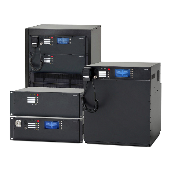
3. SEVEN system presentation SEVEN is the latest product promoted by FONESTAR SISTEMAS, S.A., the company specializing in production of reliable and certified voice alarm systems. SEVEN is a Public Address & Voice Evacuation system based on optical fibre digital transmission of voice, alarm and commercial messages. - Page 11 FMIC Box unit 4 loudspeaker line control card SEVEN-xCtrLine-4 / SEVEN-xCtrLine-44 2 loudspeaker line control card SEVEN-xCtrLine-2 SEVEN-FMIC fireman microphone SEVEN-MIC zone microphone SEVEN-MICP zone microphone with display SEVEN-MICEXT microphone keyboard extension Optional features in accordance with EN 54-16 standard: Sound signaling Delayed voice alarm introduction Gradual evacuation...
- Page 12 - 12 -...
- Page 13 - 13 -...
-
Page 14: Symbols Used In The Document
4. Symbols used in the document Warning! This symbol means a potentially hazardous situation posing a death or disability hazards Attention! This symbol means potentially hazardous situation posing medium or minor injuries and/or material loss hazards. Warning! This symbol means that using the above-mentioned products increases the risk of visual impairment. -
Page 15: Warranty Conditions
5. Warranty conditions Warranty conditions are a part of General Terms & Conditions of Delivery available at: www.fonestar.com - 15 -... -
Page 16: Requirements
6. Requirements Unused devices must be stored in the original packaging, in enclosed rooms with the ambient temperature ranging from -20°C to 70°C and relative humidity – from 5% to 95% (without condensation). Once the device has been moved from cold to warm environment, there is a risk of water condensation, which has a negative impact on device performance. -
Page 17: Installation Requirements
The SEVEN system is designed to either be mounted in a 19” RACK cabinet or to be mounted on a wall as a standalone device. -
Page 18: Device Description
7. Device description This section provides an insight into SEVEN system components: » Control units » Extension cards » Microphones and microphone extensions Internal devices 7.1.1 Control units A control unit is the main element of the system which receives audio signal and sends it to the entire system. This device manages all other elements. -
Page 19: Seven Series 320, 640 And 640-2 Units
System elements operate with the following resolution: 48KHz/32 bits/2 channels. The communication between devices at large distances is carried out in 1000BASE-X technology (optical fibre), a thanks to 2 ports with SFP modules, connection redundancy occurs. In the case of connecting devices located in one RACK-type cabinet, it is advisable to use ports with RJ45 connectors. - Page 20 Every central unit except the FMIC-BOX can work independently. Line control card configuration: » 320: 1 × xCtrLine-4 » 640: 2 × xCtrLine-4 » 640-2: 4 × xCtrLine-2 BUS1 BUS2 OUT1 OUT2 OUT3 LAN/WAN TEMP. SENSOR +48 VDC BATT Audio IN +24 VDC +48 VDC 150 mA...
-
Page 21: Seven Series 320N, 640N, 640N-2
7.1.1.2 SEVEN series 320N, 640N, 640-2N Units similar to the 320, 640, 640-2 series with the exception of the extended xNET_mini-1Gb/WAN/RS network interface. This provides more connectivity and slots for two optional SFP modules. LAN PoE BUS1 BUS2 OUT1 OUT2 OUT3 LAN/WAN RS485 FIBER... - Page 22 Table 1. SEVEN series 320, 640, 640-2 and series 320N, 640N and 640N-2 technical data SEVEN SEVEN Model 320, 640 and 640-2 320N, 640N and 640N-2 Power supply 230 V AC, IEC C14 3pin terminal Power consumption Up to 600 W (depending on configuration) Number of control slots SD HC cards with capacities up to 32 GB supported Message storage...
-
Page 23: Drawing 3. Front Panel Of Seven 320, 640, 640-2 And 320N, 640N, 640N-2 Series
SFP modules / SC/LC connector Fiber module connector Multimode or single mode type / fiber type E30 or E90, OM or OM2 Communication with PC PC software: RJ45, twisted pair connection TIA/EIA568-B via Ethernet protocol Operating temperature -5°C / +40°C Operating humidity 15% to 80% (non-condensing) Storage temperature... -
Page 24: Drawing 4. Line Control Card Arrangement For Seven Systems
CPU off section CPU off function LED (yellow) CPU off function switch Control Card slots Charger slots BUS1 BUS2 OUT1 OUT2 OUT3 TEMP. SENSOR +48 VDC BATT Audio IN Audio OUT +24 VDC +48 VDC LINE D LINE C LINE B LINE A HV AUDIO IN 320 units... -
Page 25: Seven Series 320, 640 And 640-2 Units
200X series units use two 160W amplifier modules and a single switchable transformer. This enables one of the amplifiers to work as the main unit while the second one provides redundancy 400X series units use two 320W amplifier modules with two transformers. This enables both of the amplifiers to work either simultaneously with the total output limited to 320W or with one used as main and the other one as backup. -
Page 26: Seven Series 320N, 640N, 640N-2
Battery temperature sensor input jack Main Battery connector Logic outputs 10/100 Mbps Lan/Wan port (PC connection ) 10/100/1000 Mbps Lan port 10. 10/100/1000 Mbps Lan port 7.1.1.4 SEVEN series 320N, 640N, 640N-2 Units similar to the 320, 640, 640-2 series with the exception of the extended xNET_mini-1Gb/WAN/RS network interface. This pro- vides more connectivity and slots for two optional SFP modules. - Page 27 Table 2. SEVEN series 320, 640, 640-2 and series 320N, 640N, 640N-2 technical data SEVEN SEVEN Model 320, 640, 640-2 320N, 640N, 640N-2, 640NR-2 Power supply 230 V AC, IEC C14 3pin terminal Power consumption Up to 600 W (depending on configuration) Number of control slots SD HC cards with capacities up to 32 GB supported Message storage...
-
Page 28: Drawing 7. Front Panel Of Seven 320, 640, 640-2 And 320N, 640N, 640N-2, 640Nr-2 Series
Operating temperature -5°C / +40°C Operating humidity 15% to 80% (non-condensing) Storage temperature -20°C / +70°C Storage humidity 15% to 80% (non-condensing) Case material and finish Steel with powdercoat finish Dimensions 439 (W) × 176 (H) × 354 (D) mm for 640-2NR Mount options 4 ×... -
Page 29: Drawing 8. Line Control Card Arrangement For Seven Systems
Control Card slots Charger slots BUS1 BUS2 OUT1 OUT2 OUT3 TEMP. SENSOR +48 VDC BATT LINE D LINE C LINE B LINE A HV AUDIO IN Audio IN Audio OUT +24 VDC +48 VDC 320 units 150 mA 350 mA BUS1 BUS2 OUT1 OUT2... -
Page 30: Seven-1500R Unit
7.1.1.5 SEVEN -1500R unit SEVEN-1500R units were designed to perform minor VAS system or serve as an extension unit in complex systems. In case of lack of connection with a superior unit, thanks to local configuration, it is able to carry out a fire scenario. The device attached to the main system network can receive alarm signals and digital signals and send them to other system devices. -
Page 31: Drawing 10. Diagram Of The Connector Panel For Seven-1500R Unit
Line control card configuration: » SEVEN-1500R (rack mounted version): 4 × xCtrLine-44 BUS1 BUS2 OUT1 OUT2 OUT3 LAN/WAN TEMP. SENSOR +48 VDC BATT Audio IN +24 VDC +48 VDC 150 mA 350 mA Drawing 10. Diagram of the connector panel for SEVEN-1500R unit Local audio bus outputs for 4 line control card operation Audio input Logic inputs... - Page 32 No of control inputs Control by Programmable 4 buttons and color touch screen No of relay outputs No of messages played at the same time Connector type 3 pin phoenix connector Frequency response 20 Hz - 22kHz (+0,5 / -3dB) Rated power Input impedance 250 Ω...
-
Page 33: Drawing 11. Front Panel Of Seven-1500R
Drawing 11. Front panel of SEVEN-1500R Indicators Power supply indicator (green LED) Failure indicator (yellow LED) Emergency indicator (red LED) Battery power indicator (yellow LED) Emergency button Configurable function buttons Function button activation LEDs Handheld microphone LED CPU off section CPU off function LED (yellow) CPU off function switch - 33 -... -
Page 34: Drawing 12. Line Control Card Arrangement For Seven-1500R
Control Card slots Charger slots BUS1 BUS2 OUT1 OUT2 OUT3 LINE D LINE C LINE B LINE A HV AUDIO IN LINE D LINE C LINE B LINE A HV AUDIO IN TEMP. SENSOR +48 VDC BATT Audio IN LINE D LINE C LINE B LINE A... -
Page 35: Seven Series 1500N, 1500Nr Units
7.1.1.6 SEVEN series 1500N, 1500NR units SEVEN-1500N and 1500NR units are the main PAVA centrals. Units consists 4,3’’ touch screen for ease of control and fault finding as well as fire microphone and extended network card with 2xSFP, 1xPOE and additional 2x logical input and outputs. The difference between units is in type of chasis. - Page 36 Logic inputs Auxillary power outputs Battery temperature sensor input jack Main battery connector Logic outputs 10/100 Mbps Lan/Wan port (PC connection) 10/100/1000 Mbps Lan port 10. 10/100/1000 Mbps Lan port RS485 Port Additional Logic I/O ports SFP module slot B SFP module slot A Table 4.
-
Page 37: Drawing 15. Front Panel Of Seven-1500N And 1500Nr Series
Maximum input voltage ≤ 3 Vrms Rated output voltage 100Vrms / 20 Ω, THD+N < 1% Total Harmonic < 0,1% Distortion + Noise (THD+N) Signal to Noise Ratio (SNR) > 76dB 2 × SFP module 1 Gb/s, 1 × POE 1 Gb/s, 100 Mb/s, 1 × LAN 1 Gb/s, 100 Mb/s connection; Data communication RS485 port;... -
Page 38: Drawing 16. Line Control Card Arrangement For Seven 1500N, 1500Nr Series
Handheld fireman’s microphone Built in speaker Indicators Power supply indicator (green LED) Failure indicator (yellow LED) Emergency indicator (red LED) Battery power indicator (yellow LED) Emergency button Configurable function buttons Function button activation LEDs Handheld microphone LED CPU off section CPU off function LED (yellow) CPU off function switch Display –... -
Page 39: Fmic Box
SEVEN-xNET_mini-1Gb/WAN/RS is a communication card consisting of two independent 1 Gbit network switches. The network switch no.1 is intended solely to transmit data related to basic SEVEN system functions, that is performing tasks of alarm voice system and AVB support. The network switch no. 2 is intended for remote connections. The card supports TCP/UDP/PTP/DHCP protocols and assures audio data exchange in CPU-OFF mode via an innovative FONESTAR SISTEMAS, S.A. -
Page 40: Drawing 18. Seven-Xnet_Mini-1Gb/Wan/Rs Communication Card
The communication card: » has two switches (2 LAN 10/100/1000 ports), system (for VAS communication) and for remote connections (disconnected during fire-fighting) (1 LAN/WAN 10/100 port – configurable working mode), » is equipped with VAS switch with AVB support, » allows 1Gb/s transmission speed and has optical-fiber interface (2 connectors for SFP modules), »... -
Page 41: Seven-Xnet_Mini-1Gb Communication Card
The SEVEN-xNET_mini-1Gb is a downsized version of the previous SEVEN-xNET_mini-1Gb/WAN/RS communication card. As it’s predecessor it consists of two independent 1 Gbit network switches. The network switch no.1 is intended solely to transmit data related to basic SEVEN system functions, that is performing tasks of alarm voice system. -
Page 42: Drawing 20. Seven-Xnet_Mini-1Gb Communication Card
The network switch no. 2 is intended for remote connections. The card supports TCP/UDP/PTP/DHCP protocols and assures audio data exchange in CPU-OFF mode via an innovative FONESTAR SISTEMAS, S.A. protocol. This card is not equipped with an RS485 port, POE, SFP ports and logical inputs and outputs. -
Page 43: Seven-Xctrline-4 - Control Card Of 4 Loudspeaker Lines
Ambient humidity during operation from 15% to 80% (without condensation) Storage temperature -20°C to +70°C Ambient humidity during storage from 15% to 80% (without condensation) Dimensions 70 × 160 × 30 (mm) 7.1.2.3 SEVEN-xCtrLine-4 – Control card of 4 loudspeaker lines SEVEN-xCtrLine-4 card provides 4 independent outputs of loudspeaker lines (A,B,C,D). -
Page 44: Drawing 22. Seven-Xctrline-4 Loudspeaker Lines Control Card
Drawing 22. SEVEN-xCtrLine-4 loudspeaker lines control card Table 7. Technical data of SEVEN-xCtrLine-4 Model SEVEN-xCtrLine-4 Power supply Internal form the Control Unit backplane Maximum current consumption 152 mA for 48 V Type of connector 10 pin screw terminal type PHOENIX, 5.08 mm Impedance measurement frequency 1 kHz to 48 kHz Frequency of the signal for EOL modules... -
Page 45: Seven-Xctrline-2 - 2 Loudspeaker Lines Control Card
7.1.2.4 SEVEN-xCtrLine-2 – 2 loudspeaker lines control card SEVEN-xCtrLine-2 card provides 2 independent loudspeaker line outputs (A,B).lcd The card relays of 100 V signal to loudspeaker lines from individual HV audio input located on the card’s front panel or from the internal 100 V bus available to all control cards. The card allows switching between main and back-up amplifier modules. - Page 46 Table 8. Technical data of SEVEN-xCtrLine-2 Model SEVEN-xCtrLine-2 Power supply Internal form the Control Unit backplane Maximum current consumption 121 mA for 48 V Type of connector 6 pin screw terminal type PHOENIX, 5.08 mm Impedance measurement frequency 1 kHz to 48 kHz Frequency of the signal for EOL modules 18 kHz to 24 kHz Maximum measured current...
-
Page 47: Drawing 25. Impedance Connection
Connecting loudspeaker lines illustrated with an example of xCtrLine-2 card You can connect loudspeaker lines by means of 3 methods: impedance, loop and SEVEN-EOL end-of-line module. Drawing 25. Impedance connection Drawing 26. Loop connection - 47 -... -
Page 48: Seven-Xctrline-44 - Control Card Of 4 Loudspeaker Lines
7.1.2.5 SEVEN-xCtrLine-44 – Control card of 4 loudspeaker lines SEVEN-xCtrLine-44 card provides 4 independent outputs of loudspeaker lines (A,B,C,D) with routing possibilities of 5 signals (4 × 100 V Bus, 1x high voltage individual input). Each of the line (A, B, C, D) can play different message at the same time. The card allows switching between main and back-up amplifier modules. - Page 49 Maximum power which SEVEN-xCtrLine-44 can handle is 800 W for 100 V line. Each output on the card can handle up to 200 W (100 V Line). Impedance of the speaker lines can be measured for 1kHz in service mode as well as for 20kHz in normal mode. Table 9.
-
Page 50: Loop Monitor Board Lm8200 For Short Isolators
4 zones maximal 800 Watt RMS. The IS8200 isolators are certified follow EN54-17:2005+AC2007. The system is built as shown on the next page. SEVEN system supports single LM 8200 with 4 loops SEVEN supports up to two LM 8200 – max 8 loops Drawing 29. -
Page 51: Drawing 30. Lm8200 - Board For 4 Loops
Power connection The LM8200 module includes collective power for 4 loops. MAX 4 × 150 mA, 24 VDC Picture below power input: − 24 VDC / 150 mA (per loop) Drawing 30. LM8200 – board for 4 loops To connect and power the LM8200 from SEVEN, use DDR-30L-24 converters and connect to 48 VDC (350 mA) output. It is a con- verter from 48 VDC to 24 VDC which is suitable for LM8200. -
Page 52: Drawing 32. Control Card Line Outputs Connection In Parallel With Tf06 Chokes To Lm8200 Board
Connection 100 V speaker line outputs to LM8200 board The loudspeaker lines from the x-CtrLine-4/44 control cards should be connected as shown in the diagram below: » 1 – loop number – top card » 4 – loop number – bottom card It is required to install in parallel TF-06-01 coils. -
Page 53: Drawing 33. Connecting 24Vdc To Lm8200
Connecting 24VDC to LM8200 BUS1 BUS2 OUT1 OUT2 OUT3 LINE D LINE C LINE B LINE A HV AUDIO IN LINE D LINE C LINE B LINE A HV AUDIO IN TEMP. SENSOR +48 VDC BATT LINE D LINE C LINE B LINE A HV AUDIO IN... -
Page 54: Drawing 34. Connecting Fault Output To Logical Input Available On Mini And Seven
Connecting Fault Output to logical input available on mini and SEVEN Fault out loop 1 Fault out loop 2 Fault out loop 3 Fault out loop 4 LAN PoE BUS1 BUS2 OUT1 OUT2 OUT3 LAN/WAN RS485 FIBER TEMP. SENSOR +48 VDC BATT Audio IN +24 VDC +48 VDC... - Page 55 In the Selector software: Give a name to the logic inputs – so that it is easy to identify which loop on which module is damaged. To do this, select the input card and change the name e.g. to Loop 1 etc. Choose Events and assign the...
-
Page 56: Drawing 35. Connection Of Isolators Is8200 To Loop Monitor Board Lm8200
Connecting the outputs of the LM82000 module to insolators » PIN A1: is + outgoing to 1 isolator » PIN B2: is + return from the last isolator » PIN B3: is – return from the last isolator » PIN A4: is – outgoing to 1 isolator Connection diagram with modules below: Max 10W... - Page 57 Connecting the outputs of the LM82000 module to insolators Max 200W - speakers with capacitor 2k2 5W resistior 2k2 5W resistior Drawing 36. Connection of isolators IS8200 to loop monitor board LM8200 - configuration speakers with capacitor between the isolators Connecting short-circuit isolators The isolator loop can be loaded with a maximum load of 200 W.
- Page 58 Connect the loudspeaker with a maximum of 10W to the TRAFO and WHITE outputs as below - there is no need for a capacitor to eliminate the DC component at this output. NOTE: In the absence of a loudspeaker, connect a 2k2 5W resistor to the TRAFO and WHITE connectors – without closing the circuit with a resistor or a loudspeaker, the isolator does not work! Another way to connect loudspeakers with insulators is not through a dedicated output (TRAFO / WHITE) but between lines con- necting the isolators.
-
Page 59: Assembly And Connection Of Seven-Lmk Master And Seven-Lmk Extension Sets
7.1.3 Assembly and connection of SEVEN-LMK Master and SEVEN-LMK extension sets SEVEN- LMK MASTER – loop mounting kit consists of: » 6x rubber pads » 4x 100V chokes » 2x plastic caps » 2x metal washers » 2x M6 square blots with nuts »... -
Page 60: Drawing 39. Assembly Of 100V Chokes And Rubber Pads
Place the 100V choke on the rubber pad and place another rubber pad on top. Drawing 39. Assembly of 100V chokes and rubber pads Place the second 100V choke on the rubber pad. Drawing 40. Installation of second 100V choke on top of a rubber pad Place the screw through the underside and hold it. -
Page 61: Drawing 42. Fixing 100V Chokes With A M6 Screw
Put on a rubber pad, then a plastic cap and put a metal washer on top. Screw it on with the M6. Drawing 42. Fixing 100V chokes with a M6 screw Repeat steps 3 through 6 for the remaining 100V chokes. Drawing 43. -
Page 62: Drawing 45. Connecting 20V Power Supply To Lm 8200
NOTE: Please check Drawing 32. Control card line outputs connection in paraller with TF06 chokes . Connect the 24V power supply to the LM8200. Drawing 45. Connecting 20V power supply to LM 8200 10. Mount the LM 8200 module and the DC-DC converter on the mounting rail. Place the outputs for connecting the loop with short circuit isolators towards the door. -
Page 63: Built In Amplifier Modules
7.1.4 Built in amplifier modules The SEVEN systems are equipped with built in amplifier modules. This enables standalone operation as a complete VAS system. Built in amplifier module options: SEVEN-320 series units use two 160 W RMS amplifier modules and a single switchable transformer. This enables one of the amplifiers to work as the main unit, with total audio load 320W, while the second one provides redundancy SEVEN-640 series units use two 320 W RMS amplifier modules with two transformers. -
Page 64: Seven Charger
7.1.5 SEVEN Charger The Charger module is responsible for distribution of uniterrupted power supply for all internal units and auxiliary outputs. It supplies the devices with guaranteed 42…57,6 VDC and 24 VDC. As a main source of power it uses a switching power supply Unit; as a source of back-up power supply, it uses the VRLA battery bankconsisting of four 12 V batteries with the capacity of up to 60 Ah. -
Page 65: Drawing 48. Connecting Seven-1500Nr With Seven-1500R With A Set Of 4X12V Batteries
Connecting SEVEN-1500NR with SEVEN-1500R: For connecting SEVEN-1500NR with SEVEN-1500R we can use a single set of 4x12V (VRLA) batteries which is shared between 1500NR and SEVEN-1500R. Please remember to set the capacity of the batteries on unit 1500NR only and select no batteries option in SEVEN-1500R when using the same bateries. - Page 66 Int: Ű Amplifiers supply: replaceable fuses 58 VDC Low Profile Mini 891 series blade fuse Ű 5 A for 320 series, 10 A for 640 series DC output protection Ext: Ű 48 V output: 0,5 A non replaceable PTC fuse Ű 24 V output: 0,2 A non replaceable PTC fuse Summary maximum Total output DC load shouldn’t exceed 500 W all DC output loads...
-
Page 67: External Devices
External devices 7.2.1 SEVEN-FMIC fireman microphone The fireman microphone is intended to do the following: » transmit voice messages or system warning and evacuation messages to selected zones during fire-fighting, » activate emergency messages, » call general-purpose messages, » select particular zones, »... -
Page 68: Drawing 50. Seven-Fmic Fireman Microphone
Main features: » Built-in 2 contact inputs and 2 relay outputs » Powered using PoE or external PSU » Black-box function – recording all announcements played back during an alarm » Built-in SFP modules and CAT5e for flexibility in topology choice (either loop or star) »... -
Page 69: Drawing 51. Upper Panel Of Fireman Microphone
SEVEN-FMIC Drawing 51. Upper panel of fireman microphone RJ45 socket to connect microphone extension SEVEN-MICEXT Microphone gain level adjustment from -6 dB to +6 dB 2-pin socket to connect power supply in accordance with EN54-4 RJ45 socket to support LAN connections RJ45 socket to support LAN with PoE connections – it is possible to power the microphone directly from the Control Unit via one CAT5 cable (data + voltage) Phoenix-type connector, two logic inputs or two relay outputs (every channel is configured on a case-by-case basis, and by default, both are set as parametric inputs) - Page 70 Listening speaker Output 0,5 W 78 dBA (@1 m, 1 W) Frequency response (3 dB) 450 Hz … 8 kHz Audio input Frequency response 400 Hz – 6 kHz (@3dB) Impedance 500 Ω Signal -40 to 30 dBu Sensitivity -66 dB Cable type, length spiral –...
-
Page 71: Seven-Mic Zone Microphone
7.2.2 SEVEN-MIC zone microphone Zone microphone is used to: » call general-purpose messages, » select particular zones, » send voice messages “live”. This zone microphone is used to activate general public announcements, to choose individual zones and to broadcast live voice messages. -
Page 72: Drawing 53. Seven-Mic Zone Microphone Connectors Diagram
Microphone LED indicators for: Power [green] (Power), Failure [yellow] (Fault), Evacuation [red] (EVAC) Active microphone LED – the LED signals that the device is ready to transmit a voice message, if a gong is programmed, the microphone activates shortly after the sound is emitted Functional buttons –... - Page 73 Table 13. Technical data of SEVEN-MIC zone microphone Model SEVEN-MIC via PoE (RJ45) or by additional 48 V power supply / Power supply 15 W DC connector 5,5 / 2,1 mm Protection rating IP 30 Number of outputs 2 channel audio (monitor speaker, headset) Number of inputs 4 channels (single-ended input bgm) Listening speaker...
-
Page 74: Seven-Micp - Zone Microphone With Lcd
7.2.3 SEVEN-MICP – zone microphone with LCD For intuitive and easier operation, SEVEN-MICP has been equipped with a touch-screen display. Navigation in the menu and change of settings is possible by means of both control buttons located next to LCD display, and touch-screen display. SEVEN-MICP can only be used for purposes not related to evacuation/ alarm. -
Page 75: Drawing 55. Seven-Micp Zone Microphone Connectors Diagram
Microphone Display Functional buttons – by default they support auxiliary functions when navigating in the menu: HOME – press to return to first menu page ENTER – ENTRANCE button– press to select in the microphone menu – up-arrow button – press to navigate in the microphone menu d. - Page 76 Table 14. Technical data of SEVEN-MICP zone microphone Model SEVEN-MICP via PoE (RJ45) or by additional 48 V power supply / Power supply 15 W DC connector 5,5 / 2,1 mm Protection rating IP 30 LCD, 272x480 resolution, 4.3 "resistive touchscreen Number of outputs 2 channel audio (monitor speaker, headset) Number of inputs 4 channels (single-ended input bgm)
-
Page 77: Seven-Micext - Microphone Keyboard Extension
7.2.4 SEVEN-MICEXT – microphone keyboard extension Every extension added to fireman microphone or zone microphone provides additional 20 functional buttons. The extension has two I2S interfaces to connect another extension. In accordance with EN54-16, one of the buttons should be assigned to a visual and sound signal test of the microphone unit. -
Page 78: Functional Buttons Performance
7.2.4.1 Functional buttons performance Every functional button can be associated with any VAS function possible to perform by a button push. The button function is set by program, during VAS system configuration. Depending on the function assigned to the functional button, the meaning of visual indicator signaling changes. -
Page 79: Extension Connector
7.2.4.3 Extension connector Microphones and microphone extensions are supplied with an aluminum connector. The SEVEN-FMIC microphone and the SEVEN-MICP microphone should be combined with the SEVEN-EKB extension with an aluminum connector with the dimensions 136.5x30x3 mm using two M3x8 screws. The SEVEN-MIC microphone and the SEVEN-EKB extension should be combined with the SEVEN-EKB extension with an aluminum connector with dimensions 124x30x3 mm using two M3x8 screws. -
Page 80: Drawing 57. The Way Of Connecting Microphone And Extension Using An Aluminum Connector
SEVEN-MICP SEVEN-MICEXT 136.5 mm SEVEN-MICEXT SEVEN-MICEXT 124 mm Drawing 57. The way of connecting microphone and extension using an aluminum connector - 80 -... - Page 81 (250 µV ) – 115 dB (200 mV Phantom power 30 VDC Temperature (operating) -5°C to + 40°C Ingress protection 54 // 66 – with additional packing glands Enclosure Aluminium Weight 1,2 kg Purpose of use FONESTAR noise microphone controller - 81 -...
- Page 82 7.2.6 SEVEN-EOL end-of-line supervision module SEVEN-EOL monitors the integrity of the loudspeaker line and all its branches. Monitoring of branch lines requires an EOL module for each branch. SEVEN-EOL provides a selective load for 20 kHz pilot tone only. The end-of-line module increases the reliability of the impedance-based loudspeaker supervision method.
-
Page 83: Seven-M01 Microphone
7.2.7 SEVEN-M01 Microphone The SEVEN-M01 microphone is an affordable fully analog device. It is equipped with a built in gong generated onboard the device, accessible through the switch on the back panel. The gong as well as the microphone itself has an individual volume control knob also placed on the back panel of the device. -
Page 84: Drawing 62. Connecting The Seven-M01 Microphone To Seven
Connection Diagram SEVEN-320N LAN PoE BUS1 BUS2 OUT1 OUT2 OUT3 LINE D LINE C LINE B LINE A HV AUDIO IN LAN/WAN RS485 FIBER TEMP. SENSOR +48 VDC BATT LINE D LINE C LINE B LINE A HV AUDIO IN Audio IN Audio OUT +24 VDC... -
Page 85: System Hardware Installation
8. System hardware installation Information on limiting damage consequences In order to avoid problems with Voice Alarm System Central Unit, it is advisable to get familiar with the contents of this manual before the first use of the central unit. VASCU is equipped with a set of automatic functions which are responsible for testing system efficiency. -
Page 86: Connecting Devices
Connecting devices The SEVEN central unit can be either placed in a RACK cabinet or used as a stand-alone wall mounted system. In the case of rack mount use, the cabinet schould be IP30 rated (according to EN54-2) and should be fitted with cooling fans. In order to assure compliance of VAS central unit with norms, connections: »... -
Page 87: Control Units
8.3.1 Control units This section presents examples of control units connection diagrams. 8.3.1.1 Daisy Chain Topology In CHAIN topology, the connection is not redundant. Connecting units in this system does not guarantee operation of the system in the event of communication cable damage. According to EN 54-16 norm, connections between VAS control units in a large scale system must be redundant. -
Page 88: Power And Lan Configuration
8.3.1.2 Power and Lan Configuration SEVEN-320N LAN PoE LAN PoE BUS1 BUS2 BUS1 BUS2 OUT1 OUT2 OUT3 OUT1 OUT2 OUT3 LINE D LINE C LINE B LINE A HV AUDIO IN LINE D LINE C LINE B LINE A HV AUDIO IN LAN/WAN RS485 LAN/WAN... -
Page 89: Use Of Ctc Vdtu2-B140-Dc
8.3.1.4 Use of CTC VDTU2-B140-DC • When microphones or Cu units are more than 100m away. • TCP / IP over cat3 cable or 2-wire straight cable. • Up to 150Mb/s over 500 meters. • Compatible with Multive / SEVEN cat 5 to SFP modules. 8.3.1.5 Example of Use with Systems - Point to Point Connection •... -
Page 90: Drawing 67. Point To Point Connection Example 1
SEVEN-MIC SEVEN-MIC SEVEN-MIC SEVEN-MIC SEVEN-MIC SEVEN-MIC SEVEN-MIC CU-8LCD SEVEN-MICP SEVEN-FMIC SEVEN-640N-2 SEVEN-MIC CU-11LCD CU-11LCD SEVEN-MIC SEVEN-MIC SEVEN-MIC SEVEN-MIC SEVEN-MIC SEVEN-MIC SEVEN-MIC SEVEN-MIC SEVEN-MIC SEVEN-MIC Drawing 67. Point to Point Connection Example 1 SEVEN-MIC SEVEN-MIC SEVEN-MIC SEVEN-MIC SEVEN-MIC SEVEN-MIC SEVEN-MIC SEVEN-FMIC CU-8LCD SEVEN-640N-2 SEVEN-MICP... -
Page 91: Ring Topology
8.3.1.6 Ring Topology In RING topology, the connection between system elements is redundant. The cables form a single continuous pathway for signals through each node – a ring. In the event of cable/communication optic fiber damage, the system still functions by using the remaining part of the ring. -
Page 92: Drawing 70. Ring Topology Control Units Connection (Copper Connection)
SEVEN-640N Remote mode Master mode Remote mode Master mode SEVEN-640N Drawing 70. RING topology control units connection (copper connection) - 92 -... -
Page 93: Batteries
8.3.2 Batteries It is necessary to protect batteries from short-circuit while connecting battery leads. Short-circuit may lead to system failure. Follow this manual to assure safety while connecting. Make sure the system power has been switched off before battery is connected. Once the batteries have been connected, make sure all terminals of all batteries have been protected against short-circuit. -
Page 94: Drawing 72. Battery Connection Diagram
LAN PoE BUS1 BUS2 OUT1 OUT2 OUT3 LINE D LINE C LINE B LINE A HV AUDIO IN LAN/WAN RS485 FIBER C L R TEMP. SENSOR +48 VDC BATT Audio IN Audio OUT LINE D LINE C LINE B LINE A HV AUDIO IN +24 VDC +48 VDC... -
Page 95: Microphones
8.3.3 Microphones 8.3.3.1 Fireman microphone RING-type optic fiber connection SEVEN-640N LAN PoE BUS1 BUS2 OUT1 OUT2 OUT3 LINE D LINE C LINE B LINE A HV AUDIO IN LAN/WAN RS485 FIBER TEMP. C L R C L R SENSOR +48 VDC BATT Audio IN Audio OUT +24 VDC... -
Page 96: Fireman Microphone Chain-Type Cable Connection
8.3.3.2 Fireman microphone CHAIN-type cable connection In the CHAIN-type cable connection, the first fireman microphone can be connected to the control unit via LAN PoE, whereas further microphones require external power supply. This does not apply to a system in which there are PoE switches between microphones (Switches must be supplied with fire power supply units). - Page 97 Via auxillary power connector located on the main panel of the SEVEN unit SEVEN-640N LAN PoE BUS1 BUS2 OUT1 OUT2 OUT3 LINE D LINE C LINE B LINE A HV AUDIO IN LAN/WAN RS485 FIBER TEMP. SENSOR +48 VDC BATT LINE D LINE C LINE B...
-
Page 98: Zone Microphones - Types Of Connection
8.3.3.4 Zone microphones – types of connection A zone microphone can be connected directly to VASCU via LAN or to the fireman microphone. Most zone microphones can be connected to VASCU via a certified switch. When the switch supports PoE function, only one wire (UTP/STP cat. 5e) is required to assure a proper microphone operation. - Page 99 Connecting with a certified network switch. The diagram below shows connection of 4 zone microphones via a switch with LAN PoE. SEVEN-640N LAN PoE BUS1 BUS2 OUT1 OUT2 OUT3 LINE D LINE C LINE B LINE A HV AUDIO IN LAN/WAN RS485 FIBER...
-
Page 100: Connecting Power To Zone Microphones
8.3.3.5 Connecting power to zone microphones Zone microphones can be powered either locally (48 V) or from the SEVEN central unit with PoE. Ways to power a zone microphone: Via LAN PoE (from VASCU or certified switch) SEVEN-640N LAN PoE BUS1 BUS2 OUT1 OUT2 OUT3... -
Page 101: Preparing Sound System For Vas Application
Define content, language and type of recorded messages on memory cards. (Emergency messages should suit the building and be confirmed by the Fire Marshal). To record messages, please contact FONESTAR SISTEMAS, S.A. Sp. z o.o. employee who is responsible for VAS start-up. - Page 102 The sound system must be prepared according to the instructions above. Before the team responsible for VAS system start-up arrives, send the email to proyectos@fonestar.es with information that “system is completed and ready for start-up” along with start-up date. Make sure the technicians have access to the room intended for VAS cabinets, reduce the number of third parties at the time when the system is installed.
-
Page 103: Operation Modes - Led Colors
9. Operation modes – LED colors LED indicators located on microphones and control units can signal various statuses. The tables below present the indicators and their functions. Table 19. Colors signaling on the system microphones depending on the function assigned LED 1 LED 2 FUNCTION... - Page 104 Power Safe Scenario Delay Silence Intercom Record Message Failure Delete Failure Accept Standby Table 20. LED colors of the button assigned to the function Select Zone FUNCTION Blink Block Zone Zone failure Ű short-circuit / ground fault / opening Ű impedance failure Ű...
-
Page 105: Normal Mode
Table 21. LED colors on the control unit front panel Graphic symbol Color SEVEN Control Units green POWER yellow FAILURE ALARM yellow Battery failure green Handheld microphone active yellow CPU-off function active (CPU bypass) Normal mode Power-on LED emits green light. In normal mode (no failure and locks) none of the LEDs in VASCU system emits yellow or red light. Alarm mode In this mode, all devices which are unnecessary during alarm (e.g. -
Page 106: Instruction For Performing Tests And Trials
Activating alarm mode Lift red button flap (alarm button “activate Evacuation”) and press it. However SEVEN system is not equipped with the red button protected by the flap. That means that pressing once the red button on the front panel of SEVEN activates the 5 seconds procedure (Evacuation button starts blinking RED) during which the system waits for second press of the button. -
Page 107: Failure Mode
Transmitting verbal messages when the central processing unit is faulty – CPU OFF Set the switch on the front panel in the CPU OFF position. The CPU OFF LED will light up with a steady green light. Press “push to talk”... -
Page 108: Testing The System
10.2 Testing the system Instructions for performing tests which will confirm proper efficiency of the VAS central unit. Get familiar with the VAS service manual. Check if VAS system stops performing any functions unrelated to warning while switching into alarm mode. Check if VAS system disconnects secondary sound systems (e.g. -
Page 109: Operation Instructions
Sending verbal messages to given fire zones (fireman microphone) » Open red “Evacuation” button flap and press it. At this moment VASCU will switch into alarm mode. However SEVEN system is not equipped with the red button protected by the flap. That means that pressing once the red button on the front panel of SEVEN activates the 5 seconds procedure (Evacuation button starts blinking RED) during which the system waits for second press of the button. - Page 110 Activating warning message in selected fire zones » Open red “Evacuation” button flap and press it. At this moment VASCU will switch into alarm mode. Next, choose zones you wish to send the message to. » Green LEDs corresponding with selected zones will light up on the microphone. »...
-
Page 111: Zone Microphone
11.3 Zone microphone Sending voice messages to a selected zones » Press chosen zone button. You can choose more than one zone. Green LEDs corresponding with the selected zones will light up. » Press “push to talk” button. Speak to the microphone while holding the button. Note: Depending on the settings of the “push to talk”... -
Page 112: Maintenance And Service
Considering hazardous voltage inside the operating devices, maintenance works can be performed only if the source of power has been switched off. All repairs must be carried out by qualified technicians or engineers. To send a service request, contact your nearest FONESTAR SISTEMAS, S.A. representative. -
Page 113: System Maintenance
Microphone control devices: » Control condition and proper operation of switches/touch-fields. » Check microphone overall physical condition. » Transmit a test message, use a monitoring speaker whenever the use of main speaker lines is not possible. System condition: » In case of inside the central unit chassis, it is recommended to clean it with a vacuum cleaner or use compressed air. The Central Unit must remain dry at all times, do not use water to clean it. - Page 114 Switch off AC power and check battery power system operation: Ű check if the system performs all functions related to transmitting alarm messages recorded in memory, Ű check if fireman microphone can transmit voice messages to particular zones, Ű check if the system deactivated other PA sources connected to VAS cabinet – which do not participate directly in alarming, Ű...
-
Page 115: Annual Inspection
12.2.4 Manufactures remarks Please note that FONESTAR SISTEMAS, S.A. is not responsible for results of unauthorized repairs. Any repairs of the equipment should be carried out by the FONESTAR SISTEMAS, S.A. or a service centre authorized by FONESTAR SISTEMAS, S.A.. -
Page 116: Configuration Software
13. Configuration Software 13.1 Welcome screen New configuration file localization In order to start a project a dedicated folder for the configuration file needs to be created. Caution: Do not select and existing folder with data, as these will be deleted! Selection of configuration file from a chosen location Creating a new project without saving Recent and template configuration file window... -
Page 117: Basic Configuration
Project field contains basic information on configuration of the SEVEN system. The name of the project and its author should be supplemented here, as well as a description which should include as many detailed data as possible, such as the place and date launched, specific features of the system, customized functions. - Page 118 Defining IP address pool to assign system devices This window shows the range the configurator uses to assign IP addresses to all programmable elements of the SEVEN system in the internal system network. It is possible to change the settings of the assigned pool, however it is not recommended by the manufacturer.
-
Page 119: System Configuration
(zone microphones) will not be monitored. Components In the top right part of the work field there is the tab with all available elements of the SEVEN system – the Components tab. Upon starting a new system design, the first component you should drag and drop to the workspace (the configurator will suggest and highlight a proper field) is the central unit. -
Page 120: File
13.3.1 File This opton creates a new folder in which all configuration data for a given project will be saved in. In order to create a folder, click the ”folder with a plus sign” icon. Creating a new or selecting an existing folder is the first thing to do to be able to go on with the configuration of the system. -
Page 121: Preferences
Closing the SEVEN system configuration software. 13.3.2 Preferences Path Display Mode: The SEVEN system component name display mode refers to logical input / output cards, control cards, audio inputs and audio outputs. In the Full Path mode, the name displayed consists of the name of the unit in which a given element is located, followed by a full stop and the name of the card, where the value in the brackets with # means the number of the slot in the unit in which a given card is located, and at the end, also preceded by a full stop, the name of the component is displayed. -
Page 122: System
Restore to factory defaults This function completely erases configuration files, logs and audio files from all of the devices connected to the SEVEN system. All of the memory cards will be formatted and the devices will be assigned with IP addresses from the 192.18.x.x pool. The... - Page 123 System Connection / Upload (PC -> System) This allows to send a configuration, created on a PC running the configurator software to the SEVEN system connected to that PC. Prior to sending the configuration to the system, the software verifies the configuration file.
-
Page 124: System Connection Settings
NewSystem. It must be remembered that automatic IP address acquisition should be set on the network interface controller of the computer connected to the SEVEN system. In case a DHCP server is missing, select from the settings the option of IP address automatic acquisition, the SEVEN system will detect the lack of a DHCP server and, using the AutoIP protocol, will assign an address from the special address pool 169.254.x.x to the communications card... -
Page 125: Workspace
13.3.5 Workspace Fibre-optic link horizontal line System elements arranged along this line are connected to each other by means of an optical fibre. The fibre-optic link makes the main communication loop of the system. The types of the connectors are specified in the technical documentation. Vertical line of system component connection by means of Cat5 UTP cable –... -
Page 126: Central Unit Configuration
(200-299). The Item 2 microphone is used to transmit ordinary messages in the SEVEN system, e.g. Public Address. Double-clicking the name of the audio input enables to change the generic name assigned by the configurator. Item No 3 is the Line in input located on the charger module of the SEVEN central unit. - Page 127 Audio Outputs / Name The SEVEN has 3 independent audio outputs. Double-clicking the name of the audio output enables to change the generic name assigned by the configurator. Audio Outputs / Connection This tab displays the internal connection of a given audio output. These connections are predefined in the SEVEN. The first one being wired to the internal speaker, the second one is connected to the internal 100 V bus through the amplifier modules providing 100 V signal to the line control cards and the third one is a line output located on the SEVEN charger module.
- Page 128 Paste to all function allows to copy EQ settings to all outputs available in the control unit. To do so select Copy to save the settings of the filters and then select Paste to all to propagate all filters settings to all outputs. Setting the level of threshold below 0 dB activates the audio limiter.
- Page 129 Online Parameters This tab is updated in the online mode, giving the user a live preview of the charger unit parameters. This enables the user to control the state of the battery array. Ű Battery Voltage – displays the existent voltage in the battery circuit. Ű...
- Page 130 Logical Inputs / buttons Logical Inputs tab contains all available buttons as well as logical inputs on the SEVEN central unit. The first four items in this section are buttons located on the front panel of the SEVEN. The next seven inputs are located on the charger module. Lastly, there are two additional inputs located on the xNET_mini communications card in the xxxxN series devices.
- Page 131 The configuration software accepts formats audio MP3 and wav and converts them to the PCM 48 kHz 16 bit format which is used by the SEVEN system. In addition, we can attribute an individual name to the added audio file (Message Name), which will enable its identification within the system.
-
Page 132: Fmic
Item No 1, however with a General-type priority (200-299). The Item 2 microphone is used to transmit ordinary messages in the SEVEN system, e.g. Public Address. Double-clicking the name of the audio input enables to change the generic name assigned by the configurator. - Page 133 In the window Default, we select the input status for inactivity for the option the system anticipates a closed circuit on the input, opening results in activation of the function assigned in EventCongifuration. For the situation is reverse: the system anticipates an open circuit on the input, closing results in activation of the assigned function. Logical Outputs Logical Outputs tab contains all available logical (relay) outputs on the fireman microphone.
- Page 134 FMIC editing window – continued Extension Configuration In this window the user declares the number of connected extensions. The maximum of 5 20-button extensions can be connected to the microphone. Respectively to the selected number of extensions, the configuration window will extend to include the field for additional button name editing and ability to assign a function using the Events button.
-
Page 135: Mic
13.3.8 MIC Name This field enables to assign an individual name to the MIC microphone, other than the generic name assigned by the configurator. Audio Inputs Audio Inputs field contains all available audio inputs in the zone microphone. Item 1 on the above figure, is a gooseneck condenser microphone –... - Page 136 Logical Inputs Logical Inputs tab contains all available buttons on a zone microphone. A double click on the name of a button enables to change the generic name assigned by the configurator. The Events buttons transfers the programmer directly to the EventConfiguration tab.
-
Page 137: Micp
MICP microphone touch screen menu. Groups and zones A list of defined audio outputs / zones available in the SEVEN system. A double-click on the chosen output transports it to Selected Groups and Zones field and add it to the MICP microphone touch screen menu. - Page 138 13.3.10 SEVEN-xCtrLine-2 / 4 HV Audio Inputs The name field enables to assign an individual name to the input intended to receive a 100 V signal from an amplifier output. The name is shown on the main AudIO-4/12 editing window, in the Connection tab.
-
Page 139: Priority Manager Configuration
13.4 Priority Manager Configuration Each zone microphone, fireman microphone or audio input available in the system must have its priority defined in order to ensure correct operation, as intended for sound emergency systems. Message priority mode in case of conflict – FIFO / LIFO Priority Resolve Mode –... - Page 140 Audio source type selection: Emergency, General, Service, BGM The SEVEN has 4 priority groups, each of the groups has 99 levels. Priorities are numbered in the reverse order: the fireman microphone in Emergency mode has the highest 0 priority the lowest priority is BGM 399. Priority types: Emergency, range 0-99 –...
-
Page 141: Group Zone Configuration
13.5 Group Zone Configuration This function is available only from the advanced configurator level – Basic Configuration – Configuration Mode – Advanced. It is used to combine any predefined speaker lines / zones into one. A group created in this way has the same functionalities in the system as a single zone. -
Page 142: Control I/O Configuration
13.6 Control I/O Configuration This tab is only available from the advanced configurator level – Basic Configuration – Configuration Mode – Advanced. The tab consists of 3 pages: Group Logical Inputs, Group Logical Outputs and Timers. 13.6.1 Group Logical Inputs Group Logical Inputs –... -
Page 143: Group Logical Outputs
Timers Timers functions serves to create elements triggering given actions in the SEVEN system, using time dependences. 13.6.2 Group Logical Outputs Group Logical Outputs – this is grouping of two or more logical (relay) outputs in order to simplify assignment of many relay... - Page 144 Select Logical Outputs From the tab, using the left mouse button, add elements to the group. Each of the elements can only be assigned to one group. The created group is shown in the Scenario Configuration – Add control outputs action tab, as well as in Event Configuration,...
-
Page 145: Timers
13.6.3 Timers This is a function used to create elements activating given actions in the SEVEN system. In order to create a timer, click the icon in the Control I/O Configuration – Timers tab. In this way a timer is created with the generic name Timer00000x; the name is editable by moving the mouse cursor over it and pressing the left mouse button. -
Page 146: Matrix Configuration
13.7 Matrix Configuration Matrix Configuration is used to create connections of all audio sources available in the system to audio outputs. The tab has 3 sections: creating Matrices, audio sources and speaker zones or zone group. Matrix editing tab By means of the icon , a new matrix is created with a generic name which can be change by double-clicking of the left mouse button on the matrix name. - Page 147 Matrix settings – the number of message repetitions specific to the matrix is accessible under the icon If the Infinity checkbox is ticked the message is played back in a continuous loop. Untick the checkbox to gain access to setting the number of repetitions of the message with the maximum number being 100. Test dynamic matricing –...
-
Page 148: Scenario Configuration
13.8 Scenario Configuration Scenario Configuration – this enables to create an event sequence that is time-limited in any way and executed one by one (SubScenario after SubScenario). Scenarios can consist of matrixes, logical (relay) outputs and individually created functions in the LUA language. Scenario editing tab enables to create new scenarios, changing their names and deleting selected ones. - Page 149 Icon assigns available logical (relay) outputs to a subscenario. Having added a logical output, the following windows are to be filled: Component – select an output card or fireman microphone, a communications card containing the output we want to use. Output –...
-
Page 150: Event Configuration
13.9 Event Configuration Event Configuration – this tab enables assignment of a selected system function to each logical input and button available on fireman and zone microphones, as well as scenario and matrix activation / deactivation. Moreover, in the Event Configuration –... - Page 151 The filters in the Event Configuration tab enable to search for any logical input or button sorted by the assigned function – Filter Functions, sorted by the device containing the given element – Filter Components or by using available inputs – Filter control inputs.
-
Page 152: Functions
The code of the programme which is to be placed in the Custom field must be consistent with the syntax of the LUA language and refer to variables, functions and libraries defined by the FONESTAR SISTEMAS, S.A. in the LUA language implemen- tation instructions in the SEVEN system. - 152 -... - Page 153 Failure delete results in resetting of the system element in which the failure was detected, and then running the system test procedure. General This function combines three main functionalities of the SEVEN system: Scenarios Matrices logical outputs alongside an access to RGB LED behaviour programming on zone microphones. The...
- Page 154 Output – enables to select from the available output list on the device, from the Component tab, an output which we want to control. State – allows to determine the final state of the relay contacts following activation. Active results in changing the relay state to the opposite one on execution of the General for Inactive, the relay does not change its state when the...
- Page 155 Scenario Delay This function cause a time delay in the scenario execution. The maximum time to declare a delay in a scenario execution is 600 seconds. In order to execute the scenario with a delay, activate the scenario delay function and then activate scenario execution via the General function.
- Page 156 Start / stop matricing The function enables activation or deactivation, via one logical input or button on the zone / fireman microphone, of one or many matrices, as defined in the configurator. Each matrix can be assigned an individual activation mode – start stop / toggle.
- Page 157 Volume change The volume change function controls only the levels of audio outputs in the SEVEN system. The function is activated by dynamic assignment. There are two methods of volume change execution in the configurator: Change – the level of signal at an audio output will be decreased or increased by the value declared in decibel in the Volume window compared to the level set in the audio output individual configuration window.
- Page 158 MICP microphone touch screen menu. Groups and zones A list of defined audio outputs / zones available in the SEVEN system. A double-click on the chosen output transports it to the Selected Groups and Zones field and add it to the MICP microphone touch screen menu.
- Page 159 13.9.3 NCS6 Configuration Connection and configuration The SEVEN-NSC6 module is a Noise Sensing Controller and is used to automatically adjust the volume of the signal in relation to the sound pressure level of the ambient noise in the desired area. The SEVEN-NSC6 module connects to the rest of the system using an Ethernet cable as standard TIA / EIA-568-B and the LAN or LAN / POE port, its further configuration is carried out in the Selector software.
- Page 160 NSC6 Configuration icon is used to open configuration window background microphone controller SEVEN-NSC6. To start NSC6 configuration process assigning of NSC to desired zones has to be made. To do this <<ADD has to be pressed. Then, dedicated window with available zones will be displayed. To select zones, which will be controlled by NSC please dou- ble-click on in Selected column to switch it to value.
- Page 161 After zone selection process described above, next step is to select from drop-down list Zone or Group which detailed set- tings will be defined in next step. Each volume change on zone or group can be defined with own reaction time for ambient sound pressure level change. Three modes are available: Fast, Medium, Slow.
- Page 162 Number of Thresholds is directly connected with number of Output levels parametrized in step before. Number of Thresholds equals number of Output levels -1. On above example principle of work of NSC is shown. If measured ambient sound pressure level is below 57dB (green line) then output volume will be attenuated by -20dB.
- Page 163 Further configuration is possible by double-clicking NSC6 module in system topology window. The Name field allows you to give an individual name to each NSC6 module. On-Line mode allows you to view SPL values in the Level Meter column. When the system has an updated configuration and is active, clicking the gray icon swill activate the on-line mode, which will be confirmed by a change icon color to green When online mode is active, the measured sound pressure value is displayed.
-
Page 164: The Amplifier Output Manager Tab
This allows for a guarantee of broadcasting at least 1 message for SEVEN and 2 messages for the SEVEN system in the event of failure of one of the amplifiers. - Page 165 Select all zones to set power: The column allows globally determine the range of assigned values for all speaker lines available in a system consisting of many SEVEN _ SEVEN units („System Global Settings”) or for a selected ones. Assigned power load: Assigned Power Load column contains two Spinbox items on one line to set the power globally and a button to assign this power to the line of control cards.
- Page 166 Power column: The column Power includes a button with the text “Read” used to read the power on all control cards available in the system. Support for power measurement only for xCtrline-44 card. After clicking on any of the buttons marked as Read, a popup window will appear with information confirming the willingness to take measurements.
-
Page 167: Reports
Component Report – a quantitative list of all cards, zone/fireman microphones, touch screens included in the SEVEN system. In addition, there is a summary of available audio inputs and outputs, logical inputs and individual component software versions. - 167 -... -
Page 168: Basic Steps Required To Program The System
System Reports – a list of all failures and software events that occurred during normal operation. The system is capable of storing and reading over 100 thousand single events. An advanced filtering method, using date, unit and system state, makes it much easier to identify a problem which occurred in the system. Statistic Report –... -
Page 169: Glossary
– this is an input found on each xCtrLine-4 /xCtrLine-2 control card which is used to connect an amplifier modules 100 V output to the card. In the SEVEN system it is used exclusively in the 640-2 series units to drive two of the four xCtrLine-2 cards. -
Page 170: Faq
Source 2 is also to begin transmitting to the same zone, Source No 1 will be disconnected from the zone and Source No 2 will transmit to the zone. – scripting language used to extend the functionality of the SEVEN system. This language is implemented as the C language library, written according to ANSI C, providing: simplicity, performance and code transferability. - Page 171 A downloaded running SEVEN system configuration cannot be opened The downloaded file from the system, config.afz can be found in the tab Documents –> Selector –> Workspaces_x.x.x (where x indicates the version of the software) –> downloadedConfiguration. To run the downloaded file from the system (* .afz) you need to:...
-
Page 172: Appendix
» system has no active audio matrices and operates in Normal mode (no Alarm). While working in active Standby mode the SEVEN system periodically changes its operating states to the following sample states: » active_state » suspended_state Duty cycle of the above conditions is as follows: »... - Page 173 The time is determined in minutes / The time interval [15 ... 300 minutes] Default state – checkbox enclosed, active function Default activation time: 60 minutes AutoStandby function is available in the Basic Configuration: Each attempt of audio broadcasting while Standby is active causes: »...
- Page 174 The list of faults reported by the system E: Error – fault description visible on GUI of the control unit W: Warning – access to this type of the information via Selector software – System Report only I: Info – access to this type of the information via Selector software – System Report only “E0002”...
- Page 175 “I0103” – “Event activation %xx” “I0104” – “Event deactivation %x” “I0105” – “Matrix activation %x” “I0106” – “Matrix deactivation %x” “I0107” – “Failure Accept” “I0108” – “Failure Delete” “I0109” – “Device start, dev=%x” “I0110” – “Connection state 0x%x->0x%x: %d” “I0111” – “Logical input 0x%x state changed %d” “I0112”...
- Page 176 The size of memory card in the control unit compared to available length of the message played, recorded and the number of entries in reports SD Card [MB] 1024 2048 4096 8192 16348 32768 System / CFG ** 1344 2624 Audio Message 1760 3520...
-
Page 177: Seven System Touchscreen User Manual
14. SEVEN system touchscreen user manual The following instructions describe the available functions and how to operate them from the touch screen located on the front panel of the SEVEN control units. 14.1 Home screen (screen saver) Control units in idle status display the start screen (screen saver) informing about the system status, control unit name, current date and time in the system. - Page 178 14.3 System Options System Status Icons The top left field of the screen contains information about the current state of the SEVEN system. When only the green power icon is displayed, it means that the system is in normal mode (no Alarm) and no faults have been detected.
- Page 179 14.4 Fire zones Fire Zones tab allows you to matrix an audio message / input to a selected zone or fire zones, as well as to view the status of a given zone: failure, blocks, playback with information as to which source. Note –...
- Page 180 Message window Mute function is used to mute the audio source / message globally throughout the system. Select the source, the selected source will highlight in yellow and then select the Mute icon. By clicking the back button located next to the icon you will go to the main window Fire Zones, where we can verify if the...
- Page 181 14.5 Numerical selection of fire zones It is possible to select fire zones in the system using three-digit numbers. To make this functionality active, you must give the zones names during the system configuration, including the three-digit prefix, according to the scheme XXX_zone name (e.g. 001_ZONE). After opening the Fire Zones tab, use the button near this icon...
- Page 182 It is also possible to select several zones at the same time. To do this, enter the numbers of the selected zones, placing symbol between them. Example in the graphic below. Operation is confirmed with the ENTER icon. Another option for selecting fire zones allows you to select zones whose first elements of the name are common, e.g. all names starting with the syntax 01.
- Page 183 14.6 Fire zone groups Group fire zone icon allows you to open the screen with a view of the previously defined fire zone groups. This tab allows you to perform the following actions: » check or uncheck a group of zones; »...
- Page 184 14.7 Service Service – Misc functions tab provides access to the basic functionalities needed for servicing or starting the system. Allows you to view impedance on each line of the control card, save impedance reference globally (on all cards) or on the selected output.
- Page 185 Authorization code option in the Service main menu, a 6-digit number will be displayed, which should be sent to FONESTAR SISTEMA, S.A. (proyectos@fonestar.es) to generate the authorization token. Note: a request to generate an authorization token can only be sent by the system owner or manager or a person who obtains the written consent of the owner or manager and attaches it to an email.
- Page 186 From the Service window, use the buttons up / down to go to additional functions available on the GUI: » Remote access. It is an option that allows the system to connect to a remote server, where the simultaneous activation of remote access disconnects the local server enabling connection to a computer via Selector software.
- Page 187 14.8 Fault register Failure register tab allows you to view the current damages detected by the system. The buttons located at the bottom of the screen allow viewing the failure history, sorting entries, confirming the fault (after confirming the fault acoustic signaling is turned off) and clearing the fault with calling the check function again.
- Page 188 Selecting the History icon allows you to view past failures with the ability to view failure details, sort, filter by start date, and delete the registry. Selecting the Delete the register icon clears all entries in the failure history. Deleting the history log has no effect on the system event log, available through the Selector program. - 188 -...
- Page 189 14.9 Interface setting Interface settings window is used to set the language in which the display is operated, change the time zone and display information about the expected IP address of the remote server, the signature of the system firmware version along with the project name.
-
Page 190: Annexes
15. Annexes » List of certified switches to connect devices in CHAIN topology - 190 -... -
Page 191: Certificates
16. Certificates - 191 -... -
Page 192: Glossary
17. Glossary Internal script language based on LUA language. LUA is covered by X11 license. Audio Video Bridging – technology of sending audio and video streams a computer network. FACIE Fire Alarm Control and Indicating Equipment – central part of fire signaling system powering fire detectors and receiving fire detection signals in order to trigger the alarm. -
Page 193: List Of Tables
18. List of tables Table 1. SEVEN series 320, 640, 640-2 and series 320N, 640N and 640N-2 technical data __________________________________ Table 2. SEVEN series 320, 640, 640-2 and series 320N, 640N, 640-2N technical data _____________________________________ Table 3. SEVEN SEVEN-1500R technical data __________________________________________________________________________ Table 4. -
Page 194: List Drawings
19. List drawings Drawing 1. Diagram of the connector panel for SEVEN series 320, 640 and 640-2 units _________________________________ Drawing 2. Diagram of the connector panel for SEVEN series 320N, 640N and 640N-2 units _____________________________ Drawing 3. Front panel of SEVEN 320, 640, 640-2 and 320N, 640N, 640N-2 series _______________________________________ Drawing 4. - Page 195 Drawing 34. Connecting Fault Output to logical input available on mini and SEVEN _____________________________________ Drawing 35. Connection of isolators IS8200 to loop monitor board LM8200 ____________________________________________ Drawing 37. Mounting rail assembly ________________________________________________________________________________ Drawing 38. Installation of rubber pads under 100V chokes ___________________________________________________________ Drawing 39.
- Page 196 Drawing 74. Fireman microphone cable connection – CHAIN topology ________________________________________________ Drawing 75. Fireman microphone powered through LAN PoE _________________________________________________________ Drawing 76. Fireman microphone powered from 48 V auxillary power output __________________________________________ Drawing 77. Fireman microphone powered by the fire power supply unit ______________________________________________ Drawing 78.
- Page 197 E E S S / / E E N N D D E E C C L L A A R R A A C C I I Ó Ó N N D D E E P P R R E E S S T T A A C C I I O O N N E E S S ( ( D D d d P P ) ) D D E E C C L L A A R R A A T T I I O O N N O O F F P P E E R R F F O O R R M M A A N N C C E E ( ( D D o o P P ) ) De acuerdo con el Reglamento de Productos de Construcción (UE) No 305/2011 According to Construction Products Regulation (EU) No 305/2011...
- Page 198 Type, batch or serial number or any other element allowing identification of the construction product as required pursuant to Article 11(4): V V e e r r e e t t i i q q u u e e t t a a d d e e m m a a r r c c a a C C E E y y m m a a r r c c a a d d o o e e n n l l o o s s p p a a n n e e l l e e s s . . S S e e e e C C E E m m a a r r k k l l a a b b e e l l a a n n d d m m a a r r k k i i n n g g o o n n b b o o a a r r d d s s .
- Page 199 e e v v a a l l u u a a c c i i ó ó n n y y a a p p r r o o b b a a c c i i ó ó n n d d e e l l c c o o n n t t r r o o l l d d e e p p r r o o d d u u c c c c i i ó ó n n d d e e l l a a f f á á b b r r i i c c a a b b a a j j o o e e l l s s i i s s t t e e m m a a 1 1 . . I I n n i i t t i i a a l l t t y y p p e e - - t t e e s s t t i i n n g g f f o o r r r r e e l l e e v v a a n n t t c c h h a a r r a a c c t t e e r r i i s s t t i i c c s s o o f f t t h h e e p p r r o o d d u u c c t t , , t t h h e e I I n n i i t t i i a a l l i i n n s s p p e e c c t t i i o o n n o o f f t t h h e e f f a a c c t t o o r r y y a a n n d d o o f f t t h h e e f f a a c c t t o o r r y y p p r r o o d d u u c c t t i i o o n n c c o o n n t t r r o o l l a a n n d d p p e e r r f f o o r r m m s s t t h h e e c c o o n n t t i i n n u u o o u u s s s s u u r r v v e e i i l l l l a a n n c c e e , , a a s s s s e e s s s s m m e e n n t t , , a a n n d d a a p p p p r r o o v v a a l l o o f f t t h h e e f f a a c c t t o o r r y y p p r r o o d d u u c c t t i i o o n n c c o o n n t t r r o o l l u u n n d d e e r r s s y y s s t t e e m m 1 1 .
- Page 200 Retardos para la entrada de condición de alarma por voz Pasa / Pass Delays to entering the voice alarm condition Salidas para dispositivos de alarma de fuego No aplica / Not Output to fire alarm devices applicable Micrófono (s) de emergência Pasa / Pass Emergency microphone(s) F F i i a a b b i i l l i i d d a a d d o o p p e e r r a a t t i i v v e e...
- Page 201 D D u u r r a a b b i i l l i i t t y y o o f f o o p p e e r r a a t t i i o o n n a a l l r r e e l l i i a a b b i i l l i i t t y y , , e e l l e e c c t t r r i i c c a a l l s s t t a a b b i i l l i i t t y y Variación del suministro de voltaje Pasa / Pass 16.14...
- Page 202 N N º º . . 9 9 . . P P r r e e s s t t a a c c i i o o n n e e s s N N o o r r m m a a N N o o C C a a r r a a c c t t e e r r í...
- Page 203 10.2021...
Need help?
Do you have a question about the SEVEN SYSTEM and is the answer not in the manual?
Questions and answers