Advertisement
Quick Links
Advertisement

Related Manuals for FONESTAR VELA-SYSTEM


Summary of Contents for FONESTAR VELA-SYSTEM
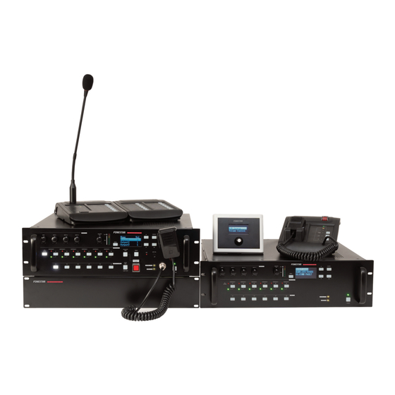
- Page 1 VELA-SYSTEM VOICE ALARM SYSTEM INSTRUCTION MANUAL...
-
Page 2: System Equipment List
VELA-PDU Power conditioner GENERAL DESCRIPTION The VELA-SYSTEM voice alarm system is an integrated emergency and general announcement broadcast system. - Each VELA-AMP/VELA-EXT has 6 outputs, and the system can expand up to 256sub zone outputs via the DANTE audio network, ie up to 42 VELA-EXT can be connected to one VELA-AMP. Each VELA- AMP/VELA-EXT can support up to 2 VELA-FMICs and 2 VELA-MICs. -
Page 3: System Configuration
SYSTEM CONFIGURATION - This example is a small systems for restaurants or small stores, etc. - Total 360 W power outputs, I-channel general broadcast system with 6 outputs. System Example 1 - 3 -... - Page 4 System Example 2 A standby amplifier is connected to this system for installation in factories or schools, etc. - Total 720 W integrated 1 - channel emergency/general broadcast system with 12 outputs - The system can be set as BGM/paging system with PC software - VELA-BUP standby amplifier is connected to the system.
- Page 5 FUNCTIONS 1.-VELA-AMP and VELA-EXT Voice Alarm System Amplifiers This VELA-AMP voice alarm amplifier funtion as the central units in the VELA system. Only one unit can be connected in the system. The front panel-mounted LCD displays setting and operation status. Up to 4pcs VELA-FMIC or VELA-MIC can be connected to one VELA-AMP. Each VELA-AMP or VELA- EXT has more than 360 W power output and is equipped with 6 speaker line outputs.
- Page 6 5.- Menu Key (MENU) - During emergency or generl broadcasts, this key can be used. - Press (MENU) to display the MENU page. 6.- OK key (OK) - During failure indicator, Stops the buzzer when a failure is detected by the surveillance function (Only for VELA-AMP) - In other Status: Functions as a confirmation key 7.- Cancel Key (CANCEL)
- Page 7 23.- Selected Output lndicators (green) [SELECT] - lndicate the speaker outputs selected with the Output Selection key - When the partition is selected, the indicator light is always on. The indicator flashes slowly while the partition is broadcasting on BGM . The indicator flashes quickly when the partition is in normal broadcast.
- Page 8 12.- Attenuator Control Outputs (ATT CTRL) - Connect to external attenuators. 13.- Direct Output Terminals - Provide pre-stage direct output signal 14.- 24 V DC Output (24 V, +.-) - Provide 24 V DC output, max 0.3 A. 15.- Funcional Ground Terminal - Hum noise may be generated when external equipment is connected to the unit.
- Page 9 10.- Emergency Microphone - After the emergency mode is activated, press the Talk key located on the side of the microphone to make an all-zone call or emergency broadcast over the selected zones. 11.- VELA-EXTMIC connector (At the bottom) - Connect the VELA-EXTMIC Extension Unit to this connector. Evacuation Announcement Key/Evacuation Indicator (EVACUATE) - This key can only be used while in emergency broadcast mode.
- Page 10 12.- RD In - Conneted to VELA-AMP or Previous equipment 13.- Message update interface - Replacing the internal message of the machine through this port. VELA-EXTMIC Zone selection controller The VELA-EXTMIC is an expansion unit for the VELA-FMIC and VELA-MIC. Up to 3 Expansion Units can be added, expanding the available function keys to up to 36 per unit.
- Page 11 VELA-BGM Panel introduction 1.- USB port 1 - You can use this port to update the program and configure the device data when you don`t use Dante. Tip: This port cannot be used simultaneously with the RS-485 communication port on the rear panel. 2.- SD Seat - The machine plays the audio file in the SD card through this interface.
- Page 12 VELA-BGM Back plate 1,. POWER - Turn on/off the device 2.- AC Seat - Mains access port 3.- Fuse slot 4.- Dante Card - The machine is connected to the LAN via a Dante card. 5.- GPS - Receiving base station signal to calibrate time. Note Since the antenna receives satellite signals, in order to ensure a good signal, the receiving end of the antenna should be placed in an open environment.
- Page 13 4.- Current track/total track 5.- the current audio playback mode (2) Play in all order Shuffle the current folder (2) All songs are randomly played (2) Single play Current folder order play 6.- Audio play progress 7.- Music mode 8.- recording mode 9.- recording recording 10.- duration Error 11.- number...
- Page 14 Routing General Input of VELA-AMP or VELA-EXT to SP outputs of VELA-AMP or VELA-EXT Step1: enable or disable the general input with PC software and set up deference priority for the general inputs if necessary. Step2: if enable Digital Input1-3, Please setup the network routing with PC software first. Step3: if enable Input1-3 or BGM.
- Page 15 Making General broadcast from VELA-AMP or VELA-EXT by activating the control inputs VELA-AMP & VELA-EXT Trigger general broadcast process Step1: Set up the Control Input function and select the broadcast group zones. Step 2:Connecting the external control switch to control input terminal. Step 3: Close or open the external control switch to start or close a general broadcast.
- Page 16 Making general broadcast from VELA-MIC VELA-MIC General broadcast flowchart 1.1 Making general MIC broadcast Step 1: Set up the select key function of VELA-MIC as "Zone Select" function with PC software Step 2: Set up the"ON/OFF"key mode :"PPT"or"LOCK" Mode with with PC software Step 3: Press the zone select key to select the broadcast zones Step 4: Press "ON/OFF"...
- Page 17 Making Emergency broadcast Three methods are used for making emergency broadcast: Press the emergency activation switch on the front panel of VELA-AMP to initiate the emergency broadcasts. Press the emergency activation switch on the front panel of VELA-FMIC to initiate the emergency broadcasts.
- Page 18 Step 1:Press emergency activation switch to enter emergency mode. Step 2:Press"ALL"key to select all zones or press the select key to select the broadcast zones Step 3:make announcement while press the emergency microphone's talk key. If skip step 2, all the zones would be selected as broadcast zones as default. Step 4:Reset the emergency mode using the below three methods: Press the "RESET"...
- Page 19 1.3 Making automatic emergency broadcast via emergency control input on the rear panel of VELA- AMP or VELA-EXT External control input signal or timing signal trigger emergency broadcast Step 1:Setup the emergency control input function and select the group zone with PC software. Step 2:When the fire alarm system is activated, an emergency control signal will output to the fire center.
- Page 20 The Equipment status and response when emergency mode is activated by external equipment. 1.1 When the emergency mode is activated by external, and the status and the response of VELA- The emergency indic ator blink and the buzzer sounds. if the emergency activation switch is pressed, The emergency indicator stop blink and keep to light up.
-
Page 21: Priority Settings
Priority Settings 1.1 Priority List Sub priority (In same broadcast System Priority type, the user can set different sub No broadcast Type (user can't priority for the broadcast generated change) from different broadcast source) External Emergency broadcast (from fire alarm system) 1-128 (Broadcast Sub priority) Emergency microphone broadcast (from VELA-AMP or 1-128 (Broadcast Sub priority) - Page 22 Surveillance 1.1 what is the Surveillance function The surveillance function continually monitor the system failure status. Included below items: the important component parts inside the equipment in this system. The important connections between equipment component in this system. The communication status in this system if a failure status is detected, the failure message would be display on LCD.
- Page 23 In this event, a failure of the contents shown on the LCD screen of VELA-AMP. Pressing the amplifier's [OK] key to acknowledge the failure and switches the yellow failure indicator from flashing to steady-on mode. The user can check the failures information on LCD by press [UP]/[DOWN] keys. If the failure is reset at the amplifier, the failure indicator goes out.
- Page 24 2) Acknowledging failures by the control input Failure acknowledgment can also be performed by using the control inputs of the VELA-AMP or VELA-EXT 1.5 Examples of Failures and User Operations 1.5.1 Failure example 1: Communications failure Assuming that the VELA-FMIC's connection is disconnected with the VELA-AMP system, when the failure is detected, the equipment operates as follows: - The buzzer of VELA-AMP sounds, the Failure indicator flashes yellow and failure information is displayed on the LCD screen.
- Page 25 The user should operates as follows: Step 1: Press the VELA-AMP's [OK] key (to acknowledge the failure). The buzzer stops and the yellow Failure indicator light switches from flashing to steady on mode. Step 2 Analyse the cause and remedy it. Then correctly reconnect the cables between the VELA-FMIC and the VELA-AMP.
- Page 26 Step 1: Press the VELA-AMP's [OK] key (to acknowledge the failure) or the VELA-FMIC's [Failure Acknowledgment] key. The buzzers on the VELA-AMP or VELA-FMIC stop and the yellow Failure indicators light on the VELA-AMP or VELA-FMIC switch from flashing to steady on mode. Step 2: Analyse and remedy the cause.
- Page 27 Local Failure Information List: Failure information Discription SP L TO Earth Ground fault caused in a speaker connected to the VELA-AMP or VELA-EXT SP L n OPEN (n=1~6) Speaker Line n of the VELA-AMP or VELA-EXT is Open-circuited SP L n CLOSE (n=1~6) Speaker Line n of the VELA-AMP or VELA-EXT is Short-circuited.
- Page 28 SETTINGS 1.1 Keys Used for Settings 1.2 Setting Hierarchical Chart 1.3 Message Updated. Because the number of stored messages is numbered according to the order in which the files are placed on your computer, it is recommended to use the following steps to update your voice information. Step 1: Edit the name of the message As follow methods in PC: xx_name.wav or xx_name.mp3 which xx must be the continuous number ,such as 01,02,03..
- Page 29 Step 2: Connect the equipment to PC via USB cable. Step 3: A new USB disk would be found on PC. Step 4: Copy all the message files into the USB disk at same time. Step 5: Removed the USB cable. Then finish the message updated. Noted: Every time the message Updated, all the message files must be copied to a new folder in PC, then delete all the files in USB disk.
-
Page 30: Installation
INSTALLATION 1.1 Installing the VELA-FMIC on a Wall WARNING! - Install the unit only in a location that can structurally support the weight of the unit and the mounting bracket. Doing otherwise may result in the unit falling down and causing personal injury and/or property damage. - Page 31 Before install to the bracket, the VELA-EXTMIC must be connected to the extension connector on the VELA- FMIC's side. Installing the VELA-MIC on a Desk WARNING! - Install the unit only in a location that can structurally support the weight of the unit and the mounting bracket.
- Page 32 Before install to the bracket, the VELA-EXTMIC must be connected to the extension connector on the VELA- MIC's side. Creating Remote Microphone Name Labels 1.- Preparation by hand Copy the "Pattern paper for hand writing" on the next page. After writing a name, cut out the pattern paper aligning it with the cutting guidelines.
- Page 33 1.3 Remote Microphone Connections 1.- Total 4pcs VELA-FMIC or VELA-MIC can be connected to VELA-AMP or VELA-EXT. Each RD port support up to 2pcs (only 1pcs VELA-FMIC can be connected). 2.- Power supply to the remote microphones Each RD port of VELA-AMP or VELA-EXT can supply power to two VELA-FMIC or VELA-MIC only. If the total distance is greater than 100M, provide external power for each VELA-FMIC and VELA-MIC as shown below.
- Page 34 1.- Controlling functions assigned to the General Control Input terminals from the external equipment. Following are assignable functions to the General Control Input terminals. (For the function assignments, refer to VELA-SYSTEM software operation manual) 2.- INPUT 1-3: Allows general broadcast received from the designa ted input to the designated output (zone).
- Page 35 1.6 Emergency Control Input Terminal Connections For Control Input 1 -4 of VELA-AMP, the Function are fixed as below: Control Input 1(Evacuation), Low level input would broadcasts the evacuation message internally pre- recorded. High level input would stop the Evacuation evacuation broadcast. Control Input 2 (Alert), Low level input would broadcasts the alert message internally pre-recorded.
- Page 36 Terminal assignment to the emergency control inputs] RJ45 connector Cable color Cable color Connector name Assignment pin No. (T568B type (T568A type) Orange/White Green/White CTRL IN 1 Orange Green COM 1 Green/White Green/White CTRL IN 2 Blue Blue COM 2 EMERGENCY Blue/White Blue/White...
- Page 37 VELA-AMP rear - 37 -...
- Page 38 1.9 VELA-EOL Connection Speaker line failure can be detected with greater accuracy when the VELA-EOL modeules are connected to the VELA-AMP's or VELA-EXT's general control inputs 1-6. Note “End of line” function must be assigned to the Emergecy control input terminal. When the speaker is directly connected to the output of the VELA-AMP/VELA-EXT, the speaker cable detection function can be set by the PC software.
- Page 39 function, battery EOL function, and battery Port function Normal mode detection is off(568A standard detection off(568B Broadcast Type (non- EOL function) network cable) standard network cable) PS port Orange White- External control input 1 External control input port 1 PS port Green White-Green Orange External control input 2 External control input port 2...
- Page 40 1.11 External attenuator connection (4-wire system) Operation status of the VELA amplifier and the corresponding attenuator operation Operation status of amplifier Attenuator operation Normal mode Normal operation At the time of emergency broadcast, or Priority 1 or 2 broadcast Bypassed - 40 -...
- Page 41 1.12 BGM/Paging system Connection and standby amplifier Connection - 41 -...
- Page 42 1.13 Connections between VELA-AMP and VELA-EXT Amplifiers - 42 -...
- Page 43 1.14 Connecting Power Supply Equipment - 43 -...
-
Page 44: Specifications
SPECIFICATIONS VELA-AMP Voice Alarm System Amplifier Power Source 220-240V ~50/60Hz Power Consumption 1100 W AC Fuse 6.3A Rated Output 360 W Frequency Response 100 Hz-15kHz, 3 dB (at 1/3 rated output) Distortion 2% or less (at rated output, 1 kHz) S/N Ratio 65 dB or more Audio Input/Output... - Page 45 VELA-EXT Voice Alarm System Extension Amplifier Power Source 220-240V ~50/60Hz Power Consumption 1100 W AC Fuse 6.3A Rated Output 360 W Frequency Response 100 Hz-15kHz, 3 dB (at 1/3 rated output) Distortion 2% or less (at rated output, 1 kHz) S/N Ratio 65 dB or more Audio Input/Output...
- Page 46 VELA-BUP Voice Alarm System Standby Amplifier Power Source 220-240V ~50/60Hz Power Consumption 1100 W AC Fuse 6.3A Rated Output 360 W Frequency Response 100 Hz-15kHz, 3 dB (at 1/3 rated output) Distortion 2% or less (at rated output, 1 kHz) S/N Ratio 65 dB or more Operating Temperature...
- Page 47 VELA-MIC Remote Paging Microphone Power Source 24 V DC (operating range: 15-40 V DC, supplied from the VELA system) Current Consumption 120 mA (VELA-FMIC), 320 mA (with 5 VELA-EXTMIC connected) Frequency Response 200 Hz-15 kHz Distortion 1% or less S/N Ratio 55 dB or more Volume Control Microphone volume control, buzzer volume control...
- Page 48 VELA-BGM Test Specification Sheet AC Power 100-240V AC 50/60Hz DC Power 24V/1A Power consumption Fuse Frequency Response 20 Hz ~20kHz Signal to noise ratio 93 dB Sampling Rate Bit rate 24 bit U disk play support USB interface 1 built-in FLASH Update voice message When using the device alone, you can connect the computer USB interface 2...
- Page 49 1.9 System connection diagram 1 Note: cable parameter see table 2 - 49 -...
- Page 50 1.10 System connection diagram 2 Note: cable parameter see table 2 - 50 -...
- Page 51 1.11 Rack - 51 -...
- Page 52 TABLA 1 VELA Series FUSE parameter list PCB No. PCB Name Fuse parameter Fuse Index HB05098 Amplifier 32A 400V Ø6*32mm UL/CE(SCHURTER) HB05098 Amplifier 3A 250V Ø2*20mm CSA/T/UL HB05074 AC INPUT 6.3A 250V Ø2*20mm CCEE/CSA/S/UL/VDE VELA-BGM AC INPUT port 1A 250V Ø2*20mm CSA/S/UL/VDE ——...
- Page 53 TABLE 2 Cable parameter list VELA-AMP Connecting Device Cable Type Connected device Cable Port name Device Port Port plug Port plug Device Port Port Name Device Module parameter 3P Terminal AC power 3P Terminal AC input 3P PLUG VELA-PDU Female cable Male Ordinary...
- Page 54 TABLE 2 Cable parameter list VELA-BUP Connecting Device Cable Type Connected device Port name Device Port Port plug Cable parameter Port plug Device Port Port Name Device Module 3P Terminal 3P Terminal AC input 3P PLUG AC power cable VELA-PDU Female Male Screw...
- Page 55 - 55 -...
- Page 56 - 56 -...
Need help?
Do you have a question about the VELA-SYSTEM and is the answer not in the manual?
Questions and answers