Sign In
Upload
Manuals
Brands
FONESTAR Manuals
Security System
SEVEN SYSTEM
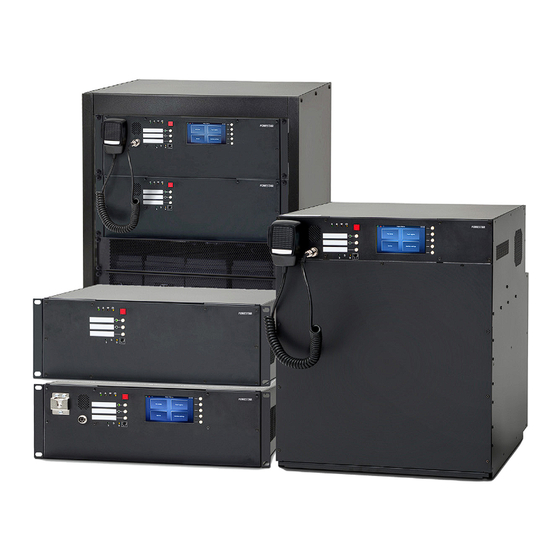
FONESTAR SEVEN SYSTEM Manuals
Manuals and User Guides for FONESTAR SEVEN SYSTEM. We have
1
FONESTAR SEVEN SYSTEM manual available for free PDF download: Manual
FONESTAR SEVEN SYSTEM Manual (203 pages)
COMPACT ALL-IN-ONE PUBLIC ADDRESS AND VOICE ALARM SYSTEM
Brand:
FONESTAR
| Category:
Security System
| Size: 45 MB
Table of Contents
Table of Contents
2
1 Safety
5
2 SEVEN System Presentation
9
3 SEVEN System Presentation
10
4 Symbols Used in the Document
14
5 Warranty Conditions
15
6 Requirements
16
Unpacking
16
Installation Requirements
17
Environmental Conditions
17
7 Device Description
18
Internal Devices
18
Control Units
18
SEVEN Series 320, 640 and 640-2 Units
19
SEVEN Series 320N, 640N, 640N-2
21
Drawing 2. Diagram of the Connector Panel for SEVEN Series 320N, 640N and 640N-2 Units
21
Drawing 3. Front Panel of SEVEN 320, 640, 640-2 and 320N, 640N, 640N-2 Series
23
Drawing 4. Line Control Card Arrangement for SEVEN Systems
24
SEVEN Series 320, 640 and 640-2 Units
25
Drawing 5. Diagram of the Connector Panel for SEVEN Series 320, 640 and 640-2 Units
25
SEVEN Series 320N, 640N, 640N-2
26
Drawing 6. Diagram of the Connector Panel for SEVEN Series 320N, 640N and 640N-2 Units
26
Drawing 7. Front Panel of SEVEN 320, 640, 640-2 and 320N, 640N, 640N-2, 640NR-2 Series
28
Drawing 8. Line Control Card Arrangement for SEVEN Systems
29
SEVEN-1500R Unit
30
Drawing 9. SEVEN-1500R Unit
30
Drawing 10. Diagram of the Connector Panel for SEVEN-1500R Unit
31
Drawing 11. Front Panel of SEVEN-1500R
33
Drawing 12. Line Control Card Arrangement for SEVEN-1500R
34
SEVEN Series 1500N, 1500NR Units
35
Drawing 13. SEVEN-1500 / 1500NR
35
Drawing 14. Diagram of the Connector Panel for SEVEN Series 1500N, 1500NR Units
35
Drawing 15. Front Panel of SEVEN-1500N and 1500NR Series
37
Drawing 16. Line Control Card Arrangement for SEVEN 1500N, 1500NR Series
38
FMIC Box
39
SEVEN-Xnet_Mini-1Gb/Wan/Rs Communication Card
39
Drawing 17. SEVEN-Xnet_Mini-1Gb/Wan/Rs Communication Card
39
Drawing 18. SEVEN-Xnet_Mini-1Gb/Wan/Rs Communication Card
40
Drawing 19. Diagram of Logical Inputs/Outputs of Communication Card
40
SEVEN-Xnet_Mini-1Gb Communication Card
41
Drawing 20. SEVEN-Xnet_Mini-1Gb Communication Card
42
SEVEN-Xctrline-4 - Control Card of 4 Loudspeaker Lines
43
Drawing 21. SEVEN-Xctrline-4 Loudspeaker Lines Control Card
43
Drawing 22. SEVEN-Xctrline-4 Loudspeaker Lines Control Card
44
SEVEN-Xctrline-2 - 2 Loudspeaker Lines Control Card
45
Drawing 23. SEVEN-Xctrline-2 Card Model
45
Drawing 24. SEVEN-Xctrline-2 Card Model
45
Drawing 25. Impedance Connection
47
Drawing 26. Loop Connection
47
SEVEN-Xctrline-44 - Control Card of 4 Loudspeaker Lines
48
Drawing 27. SEVEN-Xctrline-44 Loudspeaker Lines Control Card
48
Drawing 28. SEVEN-Xctrline-44 Loudspeaker Lines Control Card
48
Loop Monitor Board LM8200 for Short Isolators
50
Drawing 29. LM8200 Board
50
Drawing 30. LM8200 - Board for 4 Loops
51
Drawing 31. DDR-30L-24 - Converter 48 VDC to 24 VDC
51
Drawing 32. Control Card Line Outputs Connection in Parallel with TF06 Chokes to LM8200 Board
52
Drawing 33. Connecting 24VDC to LM8200
53
Drawing 34. Connecting Fault Output to Logical Input Available on Mini and SEVEN
54
Drawing 35. Connection of Isolators IS8200 to Loop Monitor Board LM8200
56
Assembly and Connection of SEVEN-LMK Master and SEVEN-LMK Extension Sets
59
Drawing 37. Mounting Rail Assembly
59
Drawing 38. Installation of Rubber Pads under 100V Chokes
59
Drawing 39. Assembly of 100V Chokes and Rubber Pads
60
Drawing 40. Installation of Second 100V Choke on Top of a Rubber Pad
60
Drawing 41. Fixing 100V Chokes with a Screw
60
Drawing 42. Fixing 100V Chokes with a M6 Screw
61
Drawing 43. Assembly of the Remaining 100V Chokes
61
Drawing 44. Connecting each of the Chokes to 100V Output
61
Drawing 45. Connecting 20V Power Supply to LM 8200
62
Drawing 46. Installation of LM 8200 Module and DC-DC Converter on Mounting Rails
62
Built in Amplifier Modules
63
Technical Details
63
SEVEN Charger
64
Drawing 47. Connection between VRLA Batteries, Temp. Sensor and SEVEN Charger Module
64
Drawing 48. Connecting SEVEN-1500NR with SEVEN-1500R with a Set of 4X12V Batteries
65
External Devices
67
SEVEN-FMIC Fireman Microphone
67
Drawing 49. Microphone Pins Diagram
67
Drawing 50. SEVEN-FMIC Fireman Microphone
68
Drawing 51. Upper Panel of Fireman Microphone
69
SEVEN-MIC Zone Microphone
71
Drawing 52. SEVEN-MIC Zone Microphone
71
Drawing 53. SEVEN-MIC Zone Microphone Connectors Diagram
72
SEVEN-MICP - Zone Microphone with LCD
74
Drawing 54. Zone Microphone with SEVEN-MICP Display
74
Drawing 55. SEVEN-MICP Zone Microphone Connectors Diagram
75
SEVEN-MICEXT - Microphone Keyboard Extension
77
Drawing 56. SEVEN-MICEXT Microphone Extension
77
Functional Buttons Performance
78
Functional Buttons Signaling
78
Extension Connector
79
Drawing 57. the Way of Connecting Microphone and Extension Using an Aluminum Connector
80
SEVEN-M01 Microphone
83
Drawing 60. SEVEN-M01 Main Control Placement
83
Drawing 61. Microphone Connector Pinout
83
Drawing 62. Connecting the SEVEN-M01 Microphone to SEVEN
84
8 System Hardware Installation
85
Information on Limiting Damage Consequences
85
General Connection Diagram
85
Drawing 63. General Connection Diagram
85
Connecting Devices
86
Control Units
87
Daisy Chain Topology
87
Drawing 64. Example of CHAIN Topology Control Units Connection
87
DIP Switch Configuration
88
Power and Lan Configuration
88
Drawing 65. Example of Power and Lan Configuration
88
Drawing 66. Example of DIP Switch Configuration
88
Example of Use with Systems - Point to Point Connection
89
Use of CTC VDTU2-B140-DC
89
Drawing 67. Point to Point Connection Example 1
90
Drawing 68. Point to Point Connection Example 2
90
Ring Topology
91
Drawing 69. RING Topology Control Units Connection (Fiber Connection)
91
Drawing 70. RING Topology Control Units Connection (Copper Connection)
92
Batteries
93
Drawing 71. 4X12 V DC VRLA Storage Batteries Connecting Diagram
93
Drawing 72. Battery Connection Diagram
94
Fireman Microphone RING-Type Optic Fiber Connection
95
Microphones
95
Drawing 73. Fireman Microphone Optic Fiber Connection - RING Topology
95
Different Ways to Power the Fireman Microphone
96
Fireman Microphone CHAIN-Type Cable Connection
96
Zone Microphones - Types of Connection
98
Connecting Power to Zone Microphones
100
Preparing Sound System for VAS Application
101
9 Operation Modes - LED Colors
103
Normal Mode
105
Alarm Mode
105
Failure Mode
105
Lock Mode
105
10 Instruction for Performing Tests and Trials
106
Instructions for Performing Basic Functions
106
Alarm Mode
106
Controlling Backup Power Batteries
107
Failure Mode
107
Testing the System
108
11 Operation Instructions
109
Control Unit
109
Fireman Microphone
109
Zone Microphone
111
12 Maintenance and Service
112
Preparations before VAS System Maintenance Works
112
Initial Procedures for System Testing
112
System Testing
112
System Maintenance
113
Daily Review
113
Inspection Every 6 Months
113
Annual Inspection
115
Manufactures Remarks
115
13 Configuration Software
116
Welcome Screen
116
Basic Configuration
117
System Configuration
119
File
120
Preferences
121
System
122
System Connection Settings
124
Workspace
125
Central Unit Configuration
126
Fmic
132
MIC
135
Micp
137
Priority Manager Configuration
139
Group Zone Configuration
141
Control I/O Configuration
142
Group Logical Inputs
142
Group Logical Outputs
143
Timers
145
Matrix Configuration
146
Scenario Configuration
148
Event Configuration
150
Functions
152
The Amplifier Output Manager Tab
164
Reports
167
Basic Steps Required to Program the System
168
Glossary
169
Faq
170
Appendix
172
14 SEVEN System Touchscreen User Manual
177
15 Annexes
190
16 Certificates
191
17 Glossary
192
18 List of Tables
193
En 19. List Drawings
194
19 List Drawings
194
Advertisement
Advertisement
Related Products
FONESTAR SEVEN-1500N
FONESTAR SEVEN-1500NR
FONESTAR SEVEN-320N
FONESTAR SEVEN-MICEXT
FONESTAR SEVEN-FMIC
FONESTAR SEVEN-640-2
FONESTAR SEVEN-NSMA
FONESTAR SEVEN-1500R
FONESTAR SEVEN-640N
FONESTAR SEVEN-1500NR15
FONESTAR Categories
Amplifier
Speakers
Racks & Stands
TV Mount
Microphone
More FONESTAR Manuals
Login
Sign In
OR
Sign in with Facebook
Sign in with Google
Upload manual
Upload from disk
Upload from URL