
Subscribe to Our Youtube Channel
Related Manuals for Srne IPC Series


Summary of Contents for Srne IPC Series
- Page 1 IPC Series Charging Bidirectional Inverter User Manual Manual version: V1.01 Subject to change without notice Code: 110598...
-
Page 2: Table Of Contents
Please keep this manual for future reference 3.1 Charging curve This manual contains all safety, installation, and operating instructions for the IPC series frequency 3.2 Charging stage description and pure sine wave charging bidirectional inverter (hereinafter referred to as "the inverter"). Please read all instructions and precautions in the manual carefully before installation and use. -
Page 3: Overview
And comprehensive electronic protections keep the entire system safer and more stable; The IPC series inverter is specifically developed as an integrated inverter and charger for RV systems. Its strong load capacity can meet the load requirements of various types of household appliances, including air conditioner, electric kettle, hair dryer, induction cooker, coffee machine, etc., meeting the needs of household appliances in RV life. -
Page 4: Dimension Drawing
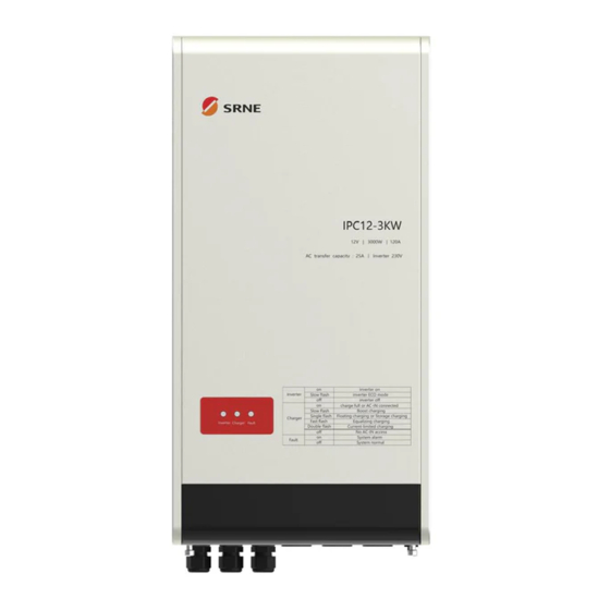
2、Technical Parameters 1.4 Dimension drawing Product model IPC12-3KW Inverter mode: output rating 3000W Withstand instantaneous impact power 6000W Output power factor Output voltage 220VAC/230VAC(default)/240VAC(±2%) Output frequency 50HZ(default)/60HZ(±0.1%) Output wave Pure sine wave Output harmonic component THDV<4%(pure resistance load) Rated input voltage 12VDC Input voltage range 10.0~16.0VDC... -
Page 5: 3、Function Introduction
3. Function Introduction 3.2 Charging stage description Corresponding to the charging curve in 3.1 above, explain each charging stage: 3.1 Charging curve 3.2.1 Stage a- precharge -Test Lead-acid batteries or lithium batteries are deeply discharged or not charged for a long time, resulting in a very low battery voltage, even down to 0V. -
Page 6: Battery Parameter Table
3. 接口功能说明 3.3 Battery parameter table 4.3 TTL communication 1) Default baud rate: 9,600 bps, check bit: none, data bit: 8 bit, stop bit: 1 bit Sealed Flooded Lithium Battery Type Gel Battery Customized 2) Communication power output specification: 12.5V/200mA Lead-acid Battery battery... -
Page 7: Remote On/Off Interface
3. 接口功能说明 4.6 Battery voltage sampling BVS interface 4.8 Operating mode switch power Since the line diameter from the battery to the inverter is too small, when the charging power is large, Using a 3-position rocker switch, with the Remote ON/OFF interface in the closed state, the inverter has the voltage collected by the inverter terminal will be higher than the actual voltage of the battery terminal, three operating modes: OFF, I, and II. - Page 8 5. Installation instructions 5.3 Installation and wiring Installation steps: 5.1 Installation precautions Step 1: Please read the user manual carefully. Step 2: Determine the installation position and the space for heat dissipation Please read this manual carefully before installation to be familiar with the installation steps. Determine the installation position (wall-mounted or horizontal installation method can be adopted): Be careful when installing battery.
- Page 9 Step 4: Wiring 3) Ac output line Connect the load equipment with inverter load and bypass load to the AC output terminal AC-OUT1, which The AC device shall be determined based on the inverter's continuous output power. The impact power of the AC device cannot be higher than the inverter's instantaneous impact power. is defined as follows: Otherwise, the inverter may be damaged.
- Page 10 Step 5: Step 7: Start the inverter 1) Close the breaker at the DC input end of the inverter or fuse at the battery end; Install other functional wiring according to actual needs, such as communication line (RS485/CAN/TTL), 2) Confirm that the Remote On/Off of the remote switch interface is in short circuit state, as shown below: battery temperature sampling line (BTS), battery voltage sampling line (BVS), remote switch control line (Remote On/Off, short circuit of terminal line by default), relay dry contact output line (NC O NO), positive and negative lines for starting battery charging (positive Start Batt-)
- Page 11 52.0 mm 一、Wall mounting Step 1: Install the wall hanger ⑤ on the wall or board with M6X30 Phillips head screw ⑤; Step 2: Hang the product ① into the wall hanger ⑤ from top to bottom, and then drive the M6X30 Phillips 401.0 mm head screw ⑤...
- Page 12 3. 接口功能说明 7. 保护功能 7. Protection Function 7.8 Inverter N-G ground protection In the inverter mode, the zero line controlled by the relay inside the inverter is connected to the grounding 3. 接口功能说明 wire, simulating the grounding of the zero line of the AC power transformer. At this time, the external leakage 7.1 DC input overvoltage protection protection can work normally and provide protection in case of leakage.
Need help?
Do you have a question about the IPC Series and is the answer not in the manual?
Questions and answers