Advertisement
Quick Links
Advertisement

Subscribe to Our Youtube Channel
Related Manuals for Srne SPI-10K-SP


Summary of Contents for Srne SPI-10K-SP
- Page 1 USER MANUAL All-in-one solar charge inverter SPI-10K-SP SPI-8K-SP V1.2...
-
Page 2: Table Of Contents
Table of Contents 1. Safety 1.1 How to use this manual ........................1.2 Symbols in this manual ........................1.3 Safety instruction ........................... 2. Production Instructions 2.1 Instructions ..........................2.2 Features ............................2.3 System connection diagram ......................2.4 Production overview ……………………………………………………………………………………………..3. - Page 3 Table of Contents 5.3 AC output mode ……………………………………………………………………………………………………… 5.4 Battery charging mode ……………………………………………………………………………………………… 5.5 Time-slot charging/discharging function ……………………………………………………………………….. 5.6 Battery parameter …………………………………………………………………………………………………… 6.Communication 6.1 Overview ……………………………………………………………………………………………………………….. 6.2 USB-B port …………………………………………………………………………………………………………… 6.3 RS485-1 port ………………………………………………………………………………………………………..6.4 CAN/RS485-2 port ………………………………………………………………………………………………..6.5 Dry contact ………………………………………………………………………………………………………..7.
-
Page 4: Safety
1. Safety 1.1 How to use this manual • This manual contains important information、guidelines、operation and maintenance for the following products:SPI-10K-SP,SPI-8K-SP • The manual must be followed during installation, using and maintenance. 1.2 Symbols in this manual Symbol Description DANGER indicates a hazardous situations which if not avoided will result in death DANGER or serious injury. -
Page 5: Production Instructions
2. Production Instructions 2.1 Instructions SPI series is a new type of solar energy storage inverter control inverter integrating solar energy storage & utility charging and energy storage, AC sine wave output. It adopts DSP control and features high response speed, reliability, and industrial standard through an advanced control algorithm. -
Page 6: System Connection Diagram
2.3 System connection diagram The diagram below shows the system application scenario of this product. A complete system consists of the following components: PV modules: converts light energy into DC energy, which can be used to charge the battery via an inverter or directly inverted into AC power to supply the load. -
Page 7: Production Overview
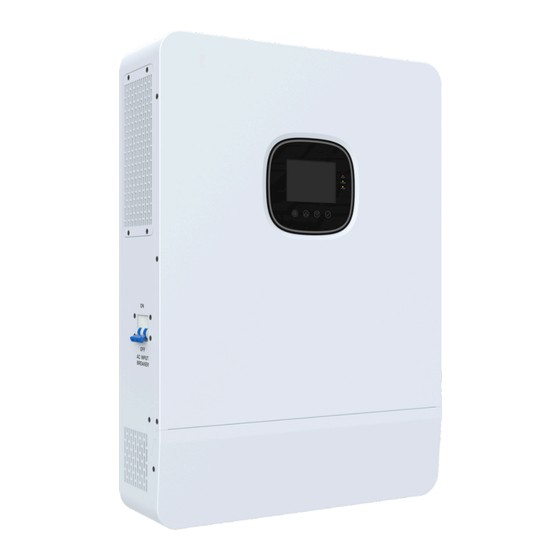
2.4 Production overview LCD screen Touchable key LED Indicators ON/OFF Rocker Switch PV INPUT (1/1) BAT INPUT (+) BAT INPUT (-) Dry contact CAN/RS485-2 port RS485-1 port USB-B port Grounding Screw AC OUT (L+N) AC IN (L+N) AC INPUT breaker Parallel Communication port (Only for parallel modules)... -
Page 8: Installation
3. Installation 3.1 Select the mount location SPI series are designed for INDOOR USE ONLY (IP20) . Please consider the followings before selecting the location. • Choose the solid wall to install the inverter. • Mount the inverter at eye level. •... -
Page 9: Mount The Inverter
3.2 Mount the inverter Make 4 mounting holes in the wall with a drill according to the specified dimensions, insert two expansion screws above and two M5 size screws below for fixing the inverter. 3.3 Remove the terminal cover Using a screwdriver, remove the terminal protection cover. Terminal cover NOTICE •... -
Page 10: Parallel Wiring Connection
3.4 Parallel wiring connection 3.4.1 Introduction • Up to six machines can be integrated into the reverse control module. • When using the parallel function, it is necessary to correctly. Securely and reliably connect the parallel communication cable, as shown in the following connection diagram (packaging accessories) : Parallel Communication Cable 3.4.2 Precautions for connecting the parallel connection cable Warning:... -
Page 11: Single-Phase Parallel Connection Guide Diagram
and PE to PE. The L-wires of all machines in the same phase need to be connected together, but the L- wires of the AC inputs of different phases cannot be connected together. Other considerations as for parallel single-phase connection. Wiring reference 2.4.4 Diagram. 5. - Page 12 2. When multiple machines are connected in parallel, the parallel connection diagrams are as follows: a. Two all-in-one solar charger inverters of the system connected in parallel b. Three all-in-one solar charger inverters of the system connected in parallel...
- Page 13 c. Four all-in-one solar charger inverters of the system connected in parallel d. Five all-in-one solar charger inverters of the system connected in parallel...
-
Page 14: Three-Phase Parallel Connection Guide Diagram
e. Six all-in-one solar charger inverters of the system connected in parallel 3.4.4 Three-phase parallel connection guide diagram Parallel communication line of the inverters needs to be connected and then screwed and locked. The schematic diagram is as follows:... - Page 15 Three-phase parallel a. Three all-in-one solar charger inverters of the system connected in three phase 1+1+1 system: b. Four all-in-one solar charger inverters of the system connected in three phase 2+1+1 system:...
- Page 16 c. Five all-in-one solar charger inverters of the system connected in three phase 2+2+1 system: 3+1+1 system:...
- Page 17 d. Six all-in-one solar charger inverters of the system connected in three phase 2+2+2 system: 3+2+1 system:...
- Page 18 4+1+1 system:...
- Page 19 NOTE: Before starting up and running, please check whether the connection was correct to avoid any abnormalities in the system. 2. All wiring must be fixed and reliable to avoid wire drop during use. 3. When the AC output is wired to the load, it shall be properly wired according to the requirements of the electrical load equipment to avoid damage to the load equipment.
-
Page 20: Connection
AC Output 230V Items Description Applicable Model SPI-8K-SP/SPI-10K-SP AC Output Voltage Range (L-N) 200~240Vac, 230Vac default NOTICE • Users can change the output voltage by setup menu. Please read the chapter 5.2 Setting. • Output voltage corresponds parameter 38 , the output voltage can be set from 200V to 240V. -
Page 22: Cable & Circuit Breaker Requirement
4.2 Cable & circuit breaker requirement • PV INPUT Model Cable Diameter Max.PV Input Current Circuit Breaker Spec SPI-8K-SP 5mm²/ 10 AWG 2P-25A SPI-10K-SP 5mm²/ 10 AWG 2P-25A • AC INPUT Circuit Model Cable diameter Breaker Output Mode Max.Input Current... - Page 23 NOTICE 6-8mm • PV INPUT、AC INPUT、AC OUTPUT Cable 1. Use a stripper to remove the 6~8mm insulation of the cable. 2. Fixing a ferrule at the end of the cable. (ferrule needs to be Ferrule Cable prepared by the user) •...
-
Page 24: Ac Input&Output Connection
4.3 AC input & output connection Connect the fire wire, zero wire and ground wire according to the cables’ position and order shown in the diagram below. AC IN AC OUT AC IN AC OUT BAT- BAT+ AC IN AC OUT DANGER •... -
Page 25: Pv Connection
DANGER • Before connecting battery, the circuit breaker must be opened to avoid the risk of electric shock and must not be operated with electricity. • Make sure that the positive and negative terminals of the battery are connected correctly and not reversed, otherwise the inverter may be damaged. -
Page 26: Dry Contact Connection
4.6 Dry contact connection Use a small screwdriver to push back the direction indicated by the arrow, then insert the communication cable into the dry junction port. (Communication cable diameter 0.2~1.5mm²) DRY CONTACT DRY CONTACT 4.7 Grounding connection Please make sure the grounding terminal connect to the Grounding Bar. NOTICE •... -
Page 27: Operation
5. Operation 5.1 Operation and display panel The operation and display panel below includes 1 LCD screen, 3 indicator lights, 4 touchable keys. screen Touchable Keys indicators • Touchable Keys Touchable Keys Description To enter/exit the setting menu To next selection To previous selection To confirm/enter the selection in setting menu... - Page 28 • LED Indicators Indicators Color Description Continued: utility grid by-pass output AC/INV Green Flash: inverter output Continued: charging complete CHARGE Yellow Flash: charging FAULT Flash: error occur • Display panel Icon Description Icon Description Indicates the PV panel Indicates the utility grid Indicates the battery Indicates the generator Indicates the inverter is...
- Page 29 Icon Description Icon Description Indicates the inverter is working Indicates the inverter is standby normally Indicates error occur Indicates setting Indicates load power 80%~100% Indicates battery SOC 80%~100% Indicates load power 60%~79% Indicates battery SOC 60%~79% Indicates load power 40%~59% Indicates battery SOC 40%~59% Indicates load power 20%~39% Indicates battery SOC 20%~39%...
- Page 30 • View real-time data In the main screen,press the UP / DOWN keys to view the real-time data of the inverter during operation. NOTICE NOTICE UP/DOWN Main Screen View Real-Time Data Real-Time Data Page PV side BAT side AC IN side LOAD side General PV voltage...
-
Page 31: Setting
5.2 Setting NOTICE NOTICE UP/DOWN Enter Setup Menu Main Screen View Parameter ENTER Edit Parameter UP/DOWN Set Parameter ENTER Confirm Parameter Parameter ID Parameter option Parameter Meaning Options Description Exit Exit the setup menu. Utility at first priority, utility and solar provide power to load at the same time when solar is available in both hybrid mode and on-grid mode, battery will provide power to load only... - Page 32 Only solar charging the battery, no utility charging. SPI-8K-SP, setting range:0~180A Battery charging current SPI-10K-SP, setting range:0~200A. User-defined, user can set all battery USER parameter. Sealed lead-acid battery. Flooded lead-acid battery. Battery type Gel lead-acid battery.
- Page 33 Parameter Meaning Options Description When the battery voltage falls below this Battery over- voltage point and item 13 value is reached, the discharge voltage inverter output will be switched off. Setting (delay off) range: 40V~48V, in steps of 0.4V. When the battery voltage is lower than item 12 of the parameter and the delay time set in this Battery over- discharge voltage...
- Page 34 Enable switch to the bypass automatically when the inverter is overload. default SPI-8K-SP, setting range: 0~100A. Max. utility charging current SPI-10K-SP, setting range: 0~120A. RS485 address setting range: 1~254. Parallel Id: 1 RS485 address mode: 1~6. [31] SIG Settings for stand-alone use.
- Page 35 Parameter Meaning Options Description Disable this function. default On-grid function, Solar is charged first and any surplus power after the load demand is met is ON GRd fed back to the grid. (Item 01 is set to UTI, item On-grid and mixed load 03 is set to UPS, item 06 is set to SNU) function Mixed load mode, solar is used in priority to...
- Page 36 Parameter Meaning Options Description 3rd slot end discharging Setting range: 00:00:00-23:59:00 default Disable this function. Time slot discharging Enable this function, AC output source function mode will switch to UTI , battery discharging only in discharging time slot which user set or utility is not available. YY/MM/DD.
-
Page 37: Ac Output Mode
5.3 AC output mode The AC output mode corresponds to parameter setting item 01 and 34, which allows the user to set the AC output power source manually. 01 UTI • Utility Priority Output (default) Utility at first priority, utility and solar provide power to load at the same time when solar is available, battery will provide power to load only when utility power is not available.(Priority: utility>solar>battery) Utility Valid Utility Outage... -
Page 38: Battery Charging Mode
5.4 Battery charging mode The charging mode corresponds to parameter setting item 06, which allows the user to set the charging mode manually. • Hybrid Charging (default) Solar and utility charging the battery at the same time, solar at the first priority, utility power as a supplement when solar power is not sufficient. - Page 39 OFF-grid and on-grid mode settings Mode Setting Options Meaning Priority Features This mode maximizes access to available power while maintaining battery power for Utility priority utility-solar-battery emergency storage and is suitable for areas with unstable power supplies. This mode maximizes the use of solar Output Solar priority solar-utility-battery...
-
Page 40: Time-Slot Charging/Discharging Function
5.5 Time-slot charging/discharging function The SPI series is equipped with a time-slot charging and discharging function, which allows users to set different charging and discharging periods according to the local peak and valley tariffs, so that the utility power and PV energy can be used rationally. -
Page 41: Battery Parameter
5.6 Battery parameter • Lead-acid battery Sealed Flooded User-defined Parameter/Battery type USER Over-voltage cut-off voltage Equalization charging voltage 56.8V 40~60V settable Boost charging voltage 57.6V 56.8V 57.6V 40~60V settable Float charging voltage 55.2V 55.2V 55.2V 40~60V settable Under-voltage alarm voltage 40~60V settable Under-voltage cut-off 40~60V settable... - Page 42 • Li-ion battery User- Ternary defined Parameter/Battery type USER Over-voltage cut-off voltage Equalization charging 40~60V voltage settable 40~60V Boost charging voltage 53.2V 57.6V 56.8V 53.2V 49.2V settable 40~60V Float charging voltage 53.2V 57.6V 56.8V 53.2V 49.2V settable 40~60V Under-voltage alarm voltage 43.6V 46.8V 49.6V...
-
Page 43: Communication
6. Communication 6.1 Overview USB-B port RS485-1 port RS485-2 port Dry contact port Parallel connection port 6.2 USB-B port USB typeB USB2.0 printer cable The user can read and modify device parameters through this port by using the host software. Please contact us for the host software installation package if you require one. -
Page 44: Rs485-1 Port
6.3 RS485-1 port The RS485-1 port is used to connect to the Wi-Fi/GPRS data acquisition module, which allows the user to view the operating status and parameters of the inverter via the mobile phone APP. RJ45 Definition Pin 1 Pin 2 Pin 3 Pin 4 Pin 5... -
Page 45: Dry Contact
6.5 Dry contact Dry contact port with 4 functions: 1. Remote switch on/off 2. Switching signal output 3. Battery temperature sampling 4. Generator remote start/ stop Temperature sampling(reserved) Switching signal output Remote on/off Generator remote on/off Function Description When pin 1 is connected with pin 2, the inverter will switched off the AC output. Remote switch on/off When pin1 is disconnected from pin2, the inverter outputs normally. -
Page 46: Fault And Remedy
7. Fault and Remedy 7.1 Fault code Alarm Fault code Fault Code Meaning Does it Affect the outputs Instructions BatVoltLow Battery under-voltage alarm Battery discharge over-current, software BatOverCurrSw protection BatOpen Battery disconnected alarm BatLowEod Battery under-voltage stop discharging alarm BatOverCurrHw Battery over-current hardware protection BatOverVolt Battery over-voltage protection... - Page 47 Fault Code Meaning Does it Affect the outputs Instructions ModelNumErr Wrong model Busdiff Busbar voltage imbalance BusShort Busbar short circuit Rlyshort Inverter output back flow to bypass LinePhaseErr Utility input phase fault BusVoltLow Busbar under-voltage protection Battery SOC below 10% alarm (Only enable BatCapacityLow1 BMS take effect) Battery SOC below 5% alarm (Only enable...
-
Page 48: Troubleshooting
7.2 Troubleshooting Fault Code Meaning Causality Remedy Closing the circuit breaker. No power input, or in sleep Ensure the rocker switch is ON. Screen no display mode. Push any button on the panel to exit sleep mode. The battery voltage is Charge the battery and wait until the battery Battery under-voltage lower than the value set in... -
Page 49: Protection And Maintenance
8. Protection and Maintenance 8.1 Protection features Protection Feature Instruction When the charging current or power of the PV array configured PV input current/power exceeds the PV input rated value, the inverter will limit the input limiting protection power and charge at the rated. If the PV voltage exceeds the maximum value allowed by the PV input over-voltage hardware, the machine will report a fault and stop the PV boost to... -
Page 50: Maintenance
Protection Feature Instruction (102%<load<110%) ±10%: error and output shutdown after 5min; Inverter over-load (110% < load < 125%) ±10%: error and output shutdown after 10s. protection Load > 125% ±10%: error reported and output switched off after 5s. Prevents AC back flow from the battery inverter to the bypass AC AC output reverse input. -
Page 51: Datasheet
9. Datasheet MODEL SPI-8K-SP SPI-10K-SP CAN BE SET INVERTER OUTPUT Rated Output Power 8,000W 10,000W Max.Peak Power 12,000W 15,000W Rated Output Voltage 230Vac(Single phase) Load Capacity of Motors Rated AC Frequency 50/60Hz Waveform Pure Sine Wave Switch Time 10ms(typical) Parallel capacity... - Page 52 MODEL SPI-8K-SP SPI-10K-SP CAN BE SET GENERAL Dimensions 620*445*130mm(2.03*1.46*0.43ft) Weight 27kg (59.52lb) Protection Degree IP20,Indoor Only -10~55℃, >45℃ derated Operating Temperature Range (14~131℉,>113℉ derated) Noise <60dB Cooling Method Internal Fan Warranty 2 Years COMMUNICATION Embedded Interfaces RS485 / CAN / USB / Dry contact External Modules (Optional)...
Need help?
Do you have a question about the SPI-10K-SP and is the answer not in the manual?
Questions and answers