Bose SoundDock Portable Service Manual
Digital music system
Hide thumbs
Also See for SoundDock Portable:
- Owner's manual (76 pages) ,
- Quick setup manual (1 page) ,
- Owner's manual (25 pages)
Table of Contents
Advertisement
Quick Links
Advertisement
Table of Contents

Subscribe to Our Youtube Channel
Related Manuals for Bose SoundDock Portable


Summary of Contents for Bose SoundDock Portable
- Page 1 Digital Music System ® February 16, 2009 - The Apple Computer security chip (U7042) was added to the DSP board to provide “Works With iPhone” compatibilty. DOM 9026. ©2007 Bose Corporation Service Manual Reference Number 300657-SM Rev. 10 Electronic Copy Only...
-
Page 2: Table Of Contents
CONTENTS Safety Information ..........................3 Specifications ............................ 4 Part List Notes ..........................5 Electrostatic Discharge Sensitive (ESDS) Device Handling ............5 Warranty .............................5 Product Description ........................6-7 Power Supply Part List ........................8 Packaging Part List ........................... 9 Figure 1. Packaging Exploded View ....................9 Speaker Assembly Part List ...................... -
Page 3: Safety Information
THIS DOCUMENT CONTAINS PROPRIETARY INFORMATION OF BOSE CORPORATION WHICH IS BEING FURNISHED ONLY FOR THE PURPOSE OF SERVICING THE IDENTIFIED BOSE PRODUCT BY AN AUTHORIZED BOSE SERVICE CENTER OR OWNER OF THE BOSE PRODUCT, AND SHALL NOT BE REPRODUCED OR USED FOR ANY OTHER PURPOSE. -
Page 4: Specifications
SPECIFICATIONS Electrical Power Supply Input: Voltage: 100VAC to 240VAC (universal), 50-60Hz Current Consumption: 1 A (rms) max for 115VAC .5 A (rms) max for 230VAC Power Supply Output: +/- 1V DC Voltage: Current: 2A (max) SoundDock ® Input: Voltage: 20V, +/- 1V Current Consumption: 2 Amp (max, continuous) Power Consumption:... -
Page 5: Part List Notes
ELECTROSTATIC DISCHARGE SENSITIVE (ESDS) DEVICE HANDLING This unit contains ESDS devices. We recommend the following precautions when repairing, replacing or transporting ESDS devices: • Perform work at an electrically grounded work station. • Wear wrist straps that connect to the station or heel straps that connect to conductive floor mats. -
Page 6: Product Description
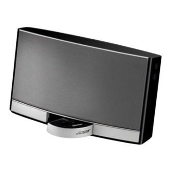
PRODUCT OVERVIEW PRODUCT DESCRIPTION The SoundDock ® Portable Digital Music System is the next product in the line of Bose ® iPod speaker systems. It offers all of the features of the original SoundDock and adds rechargeable battery enabled portability, a stow-away dock, an auxiliary input and a fresh appearance. - Page 7 Note that the SoundDock Portable battery expected life time is about 3 years or 300 charging cycles. Additional batteries are available separately.
-
Page 8: Power Supply Part List
System. Each has a unique mechanical interface. One is circular and the other is rectangular, they are not interchangable. Use the part list below to identify the part numbers needed for each version of the supply. ® Description Bose Part Note Number PWR PACK, 20V, 2A, BLK (rectangular) -
Page 9: Packaging Part List
PACKAGING PART LIST BOSE ® SOUNDDOCK PORTABLE DIGITAL MUSIC SYSTEM Item Description Part Number Note Number OWNERS GUIDE, MAX, 8L, US/EU/UK 300673 OWNERS GUIDE, SD P, 6L, AP 306331 SEE POW ER SUPPLY DETAILS ON PAGE 7 SEE AC PRONG DETAILS ON PAGE 7... -
Page 10: Speaker Assembly Part List
SPEAKER ASSEMBLY PART LIST BOSE ® SOUNDDOCK PORTABLE DIGITAL MUSIC SYSTEM Item Number Description Part Number Note BAFFLE, FRONT, SHEET METAL NUT PLATE, LEFT 300679-001 RECHARGE, LI-ION, BATTERY PACK, BLK 043517 RECHARGE, LI-ION, BATTERY PACK, WHT 043516 SCREW, 6-13 X .625, PAN, XREC/SQ... -
Page 11: Baffle Assembly Part List
BAFFLE ASSEMBLY PART LIST BOSE ® SOUNDDOCK ® PORTABLE DIGITAL MUSIC SYSTEM Item Description Part Number Note Number FOAM, TOP, PORON 308109-002 PAD, THERMAL 303561-001 *AMP BOARD, SVC, ROHS *307960-002 CABLE, FFC, 25POS, 38MM 301956-038 SCREW, TAPP, 6-32 x .375, PAN, TORX... -
Page 12: Dock Assembly Part List
DOCK ASSEMBLY PART LIST BOSE ® SOUNDDOCK ® PORTABLE DIGITAL MUSIC SYSTEM Item Description Part Number Note Number TOP CRADLE, BLK 300690-001 TOP CRADLE, WHT 300690-002 DOCK, SVC BOARD 307958-002 INSERT CLIP 303567-001 CABLE, FFC, 8POS, 0.5P, 155MM 303564-155 CABLE, FFC, 10POS, 0.5 MMP, 165MM... -
Page 13: Electrical Part Lists
ELECTRICAL PART LIST DSP PCB Assembly Resistors Reference Description Part Number Note Designator R7000 10K, 0603, .1W, 1% 191465-1002 R7001 10K, 0603, .1W, 1% 191465-1002 R7002 15K, 0805, .1W, 1% 133625-1502 R7003 15K, 0805, .1W, 1% 133625-1502 R7004 10K, 0603, .1W, 1% 191465-1002 R7006 1M, 0603, .1W, 5%... - Page 14 ELECTRICAL PART LIST DSP PCB Assembly Resistors (continued) Reference Description Part Number Note Designator R7222 10K, 0603, .1W, 1% 191465-1002 R7231 100K, 0603, .1W, 1% 191465-1003 R7232 3.9K, 0603, .1W, 1% 191465-3901 R7233 6.19K, 0603, .1W, 1% 191465-6191 R7238 100 OHM, 0603, .1W, 5% 199403-101 R7241 100 OHM, 0603, .1W, 5%...
- Page 15 ELECTRICAL PART LIST DSP PCB Assembly Capacitors Reference Description Part Number Note Designator C7000 180pF, 0603, COG, 50V, .1% 188454-181 C7001 180pF, 0603, COG, 50V, .1% 188454-181 C7002 180pF, 0603, COG, 50V, .1% 188454-181 C7003 180pF, 0603, COG, 50V, .1% 188454-181 C7004 180pF, 0603, COG, 50V, .1%...
- Page 16 ELECTRICAL PART LIST DSP PCB Assembly Capacitors (continued) Reference Description Part Number Note Designator C7217 0.1uF, X7R, 0603, 50V, 10% 191470-104 C7225 0.1uF, X7R, 0603, 50V, 10% 191470-104 C7226 10uF, EL, 85, 16V, 20% 177902-100C C7227 10uF, EL, 85, 16V, 20% 177902-100C C7228 0.1uF, X7R, 0603, 50V, 10%...
- Page 17 ELECTRICAL PART LIST DSP PCB Assembly Integrated Circuits Reference Description Part Number Note Designator U7000 IC, OP-AMP, LO-PWR, 1MHz, SC-70 302888-001 U7006 IC, INVERTER, SMD 266582-001 U7008 IC, VOLT REG, SMD, POS, SOT89, +5V 258167-05 U7010 IC, RESET, SOT-23, MAX809, 2.63V 191158-06 U7011 IC, DSP, TMS320DA705, MASKED...
- Page 18 ELECTRICAL PART LIST DSP PCB Assembly Capacitors (continued) Reference Description Part Number Note Designator C7407 3300pF, 0603, X7R, 50V, .1% 191470-332 C7409 100pF, 0603, X7R, 50V, .1% 191470-101 C7410 330pF, 0603, X7R, 50V 191470-331 C7411 330pF, 0603, X7R, 50V 191470-331 C7427 0.1uF, X7R, 0603, 50V, 10% 191470-104...
- Page 19 ELECTRICAL PART LIST Amplifier PCB Assembly Resistors Reference Description Part Number Note Designator R7116 100K, 0603, .1W, 1% 191465-1003 R7224 10 OHM, 0603, .1W, 5% 199403-101 R7225 121K, 0603, .1W, 1% 191465-1213 R7226 121K, 0603, .1W, 1% 191465-1213 R7227 121K, 0603, .1W, 1% 191465-1213 R7228 121K, 0603, .1W, 1%...
- Page 20 ELECTRICAL PART LIST Amplifier PCB Assembly Capacitors (continued) Reference Description Part Number Note Designator .1uF, X7R, 0603, 50V, 10% 191470-104 C7219 .01uF, EL, 105C, 25V, 20% 269823-103EZ C7240 100pF, 0603, X7R, 50V, .10% 191470-101 C7241 3300pF, 0603, X7R, 50V, .10% 191470-332 C7242 3300pF, 0603, X7R, 50V, .10%...
- Page 21 ELECTRICAL PART LIST SPS (Switching Power Supply) PCB Assembly Resistors Reference Description Part Number Note Designator 10 OHM, 0603, .1W, 5% 199403-100 R003 10 OHM, 0603, .1W, 5% 199403-100 R004 1K, 0603, .1W, 5% 199403-102 R005 1K, 0603, .1W, 5% 199403-102 R006 100K, 0603, .1W, 1%...
- Page 22 ELECTRICAL PART LIST SPS (Switching Power Supply) PCB Assembly Capacitors (continued) Reference Description Part Number Note Designator .01uF, 0603, X7R, 50V, 10% 191470-103 C010 1000pF, 0603, X7R, 50V, 10% 191470-102 C011 1000pF, 0603, X7R, 50V, 10% 191470-102 C012 47uF, 7343, TANT,16V, LO-R, 10% 275411-476 C013 100uF, 7343, TANT, LO-R, 10%...
- Page 23 ELECTRICAL PART LIST SPS (Switching Power Supply) PCB Assembly Transistors Reference Description Part Number Note Designator XSISTOR, MFET, P, SOT-23, 40V, 3.0A 303215-001 XSISTOR, MFET, P, SOT-23, 40V, 3.0A 303215-001 Integrated Circuits Reference Description Part Number Note Designator IC, PWM, VOLTAGE CONTROLLER, TPS40200 303218-001 IC, PWM, VOLTAGE CONTROLLER, TPS40200 303218-001...
- Page 24 ELECTRICAL PART LIST I/O PCB Assembly Resistors Reference Description Part Number Note Designator 100K, 0603, .1W, 1% 191465-1003 R4000 15K, 0805, .1W, 1% 133625-1502 R4001 39K, 0603, SMD, .1W, 5% 199403-393 R4002 39K, 0603, SMD, .1W, 5% 199403-393 R4003 Capacitors Reference Description Part Number...
- Page 25 ELECTRICAL PART LIST IR PCB Assembly Resistors Reference Description Part Number Note Designator 100 OHM, 0603, .1W, 5% 199403-101 R2000 Capacitors Reference Description Part Number Note Designator .1uF, X7R, 0603, 50V, 10% 191470-104 C2000 Inductors Reference Description Part Number Note Designator BEAD, FERRITE, CHIP, 1806 256116-181...
-
Page 26: Disassembly Procedures
DISASSEMBLY PROCEDURES 1. Grill removal 1.1 The grill is removed by pulling from the top center. The left and right sides of the grill are molded to fit inside the main assembly. Pulling from the center allows the left and right sides to dislodge and be removed. - Page 27 DISASSEMBLY PROCEDURES 3. Dock Removal 3.1 Once the baffle assembly has been removed, lift up the four rubber feet. See Figure 9. 3.2 Remove the four phillips screws. Figure 9 3.3 Remove the dock assembly being careful not to damage the two cables that feed into the main assembly.
- Page 28 DOCK RE-ASSEMBLY PROCEDURES 1. Dock Re-assembly Figure 13 1.1 Place the spring into the slotted groove on the bottom plate as shown in figure 14. Figure 14 1.2 Place the other side of the spring into the slotted groove on the dock as shown in figure Figure 15 1.3 Turn the dock counter clockwise one full rotation.
-
Page 29: Test Procedures
3.3 Listen for any extraneous noises such as B. Frequency = 80Hz +10% buzzes, rattles, ticks, and distortion. 1.3 Apply power to the SoundDock Portable, the system will default to the AUX input if PASS if no noise can be heard at a distance there is nothing connected to the dock. -
Page 30: Iphone Test Procedures
TEST PROCEDURES CONTINUTED speakers. SoundDock ® Portable iPhone Test 2.2 Place the iPhone on the dock. Equipment Required ® Apple iPhone. 2.3 Press the play button on the remote, SoundDock system built after January 26th adjust the volume to a moderate level. 2009 (DOM 9026) See cover page for de- Confirm audio is clean and no distortion can tails. -
Page 31: Tap Command Set Up
Eliminator PCB, P/N 287089 ETAP Cable, P/N 309866-001 Notes: TAP commands can be sent to the SoundDock Portable system by connecting a PC to the iPod eliminator board via the 30 pin dock connector. An ETAP cable, iPod eliminator PCB and... - Page 32 None. Accessories, Communications then Hyper Terminal. 1.2 The new connection box will appear, type in SoundDock Portable as the name. Then select OK. 2. Configuring the properties and the ASCII settings 2.1 Once the Hyper terminal is running, 1.3 Confirm the Connect using option is set...
- Page 33 TAP COMMAND SET UP CONTINUED 2.2 Change the Emulation to Auto detect, then select ASCII setup. 2.3 Select Echo typed characters locally, Append line feeds to incoming line ends and Wrap lines that exceed terminal width. Then select OK. 2.4 Once these changes have been made, select OK.
-
Page 34: Amplifier Gain Procedure
1. Setting the Default Gain 1.1 Use the TAP command set up procedure to allow the SoundDock Portable system to receive TAP commands (see TAP command setup on page 29). 1.2 Issue TAP command SP 109, 8D87 to set the gain to 36231. -
Page 35: Battery Test
BATTERY TEST ® 1.4 The results are returned with a Hex num- SoundDock Portable Digital Music ber with the bytes in reversed order. Convert Battery test this number to decimal and confirm it is less than 250. Equipment Required Example - 0200 is displayed iPod Eliminator PCB, P/N 287089 Tap Cable- part number 309866-001 Number of cycles = 2... - Page 36 BATTERY TEST CONTINUED 4.0 V Balance 4.1 To calculate V Balance, all four cell voltages need to be collected. Perform the cell commands below and execute the “Check Read Status” SP 506 and “Get Results” SP 507 after each command to read the results.
-
Page 38: Revision History
SERVICE MANUAL REVISION HISTORY Date Revision Level Description of Change Change Driven By Pages Affected 08/17/07 Document released at revision 00 Service Manual release 10/09/07 Added universal inserts Part missing from original Part number change Changed power supply part numbers from 301141- 001 and -002 to 301141-011 and -012 12/03/07 DSP part number change –... - Page 39 SPECIFICATIONS AND FEATURES SUBJECT TO CHANGE WITHOUT NOTICE Bose Corporation The Mountain Framingham Massachusetts USA 01701 P/N: 300657-SM Rev. 10 5/2008 (H) http://serviceops.bose.com...
Need help?
Do you have a question about the SoundDock Portable and is the answer not in the manual?
Questions and answers