
Subscribe to Our Youtube Channel
Related Manuals for Global DN 2220


Summary of Contents for Global DN 2220
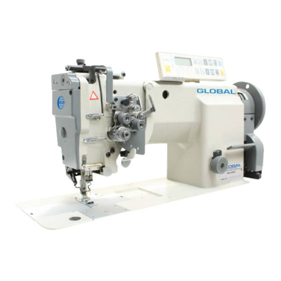
- Page 1 GLOBAL DN 2220 / DN 2200-LH DN 2220-AUT / DN 2220-LH Instruction & Parts manual www.globalsew.com info@globalsew.com...
-
Page 4: Gauge Parts
N ee d l e b a r roc k in g motion mechanism ---- - - --- -· - --------- ------------- ------------ - - -------- ---------------- ---------------------------------- ----------------- 5 . Stitch regulator mechanism ------- ··· ------- ··-------------------------- --------- 6. L o w er sha ft & feed rock shaft me c hanism 7. -
Page 5: Safety Precautions
PRECAUTIONS BEFORES STARING OPERATION 1. Safety precautions I) When turning the power on, keep your_hands and fingers away from the area around/under the needle and the area around the pulley. 2) Power must be turned off when the machine is not used, or when the operator leaves his/her seat. 3 ) The power must be turned off before tilting the machine head, installing or removing the "V"... -
Page 6: Preparation For Operation
PREPARATION FOR OPERATION - Operation box r.:>,.Jlt.-,;m::,c:1--��;;;-;;""' Balance wheel (included synchronizer) overall view of assembled sewing machine pe seNo motor ceptacles for Control box 1. Power cable connection 1) Connection to Power Supply When connecting the power· supply connector to the control box, the connector should be completely plugged in the proper receptacle after confirming the connector type and matching direction. - Page 7 The wire connections should be, then, insulated by wrapping insulating tape on the wires. CAUTION: The power switch must be Turned off before connecting the lamp. B. When the illumin_ a ting lamp is not used, the end of the lamp leads must be insulated as (a) or (b) as shown in the figure on right side'.
-
Page 10: Winding Of Bobbin Thread
Adjustment: Winding of bobbin thread Note: When bobbin thread is wound, keep the presser foot lifted. Tension of wound thread • Slack 'Winding is recommended for polyester thread and nylon thread. Conically wound thread Move the thread guide toward smaller diameter of wound thread layer. Length of wound thread Loosen the thread length adjusting screw to increase length of thread and tighten the screw to decrease length of thread. -
Page 11: Adjustment Of Feed (Stitch) Length And Stitch Reversing (Touch Back)
Note: To make feed (stitch) length smaller, depress the feed reverse lever and set the feed length setting dial to a desired position Touch-back button ... Direction of stitching can be reversed by depressing this button. Stitching goes on in reversed direction while the button is held down, and returns to forward direction when the button is released. - Page 12 Adjusting of needle thread guide Please adjust needle thread guide of needle thread tension according to sewing condition. "::::;:- Thread Thread Left lti'ddle' Ri<:ht � cuide �;.i) �) poi;it ion �) ·- --·- - � L� The thicker The thirinf'lr Sta11d- l!aterials then...
-
Page 13: Adjustment Of Presser Foot Pressure
A, B and two of C should be loosened. Note: In the adjustment, do not excessively loosen set fabric and thread by changing intensity and movable range of slack thread adjusting spring. 12. Adjustment of presser foot pressure Preo&uro regu I ot i ng thunt, ecrew Pressure to fabtic(s) can be adjusted by turning The pressure adjusting screw. -
Page 15: Adjustment Of Feed Dog Height
16. Adjustment of feed dog height Height of feed dog and pressure of presser foot should o.amrr be adjusted for individual fabric(s) with the following ,zz,� cautions: • Fabric will be damaged if the feed dog exter.ds too high, or pressure of presser foot is too large. •... -
Page 16: Relationship Between Hook Motion And Opener Motion
A ppr ox. 0.2mm 18. Relationship between hook motion and opener motion Tum the balance wheel by hand and stop when the opener holder is located most remotely from the throat plate. Make sure gap between the bobbin case holder A and the opener is approximately 0.2mm. -
Page 18: Adjustment Of Needle Threads Tension Release Assembly
To adjust, loosen two thread trimmer cam clamp screws A. To adjust, loosen two tension release cam clamp screws A. Opening degree of tension disc should be adjusted with the tension release roller B mounted on the Turning the balance wheel by hand, adjust the thread t. :i,1mer cam so that the movable knife starts moving when the green mark point on the balance wheel comes in line with the black mark point on the arm. -
Page 19: Adjustment Of Meshing Pressure Of Movable Knife And Fixed Knife
b. Turn the vertical positi?n adjusting screw B to adjust meshing pressure and then righter the hexagon Loosen two connecting link clamp bolts J. clamp bolt J. Loosen the nuts G and H. Depress the cam follower crank K and adjust the connecting rod L so that the cam roller can smoothly enter the groove of thread trimmer cam .. -
Page 20: Wiper Adjustment
Bare groove surface as small as possible, and tighten the nuts iii. Push the cam follower crank again and check that the cam roller enters into the thread trimmer cam groove smoothly. Cam follower crank Lower shaft Screw A Cam groove� phase Thread trimmer rocking crank C Connecting... - Page 21 SPECIFICA'f!ONS DN-2220 Model ' • JlN-2220-AlU'JI'. DN-222 0 /lL H nN�2220/JLH- Application Light to medium heavy material Medium heavy material Max. sewing 3500rpm 3000rpm speed 0..5mm 0,.._,7mm Stitch length 32mm Needle-bar stroke Presser-foot stroke 13mm by Leg 7mm by hand DPX5 11#-14# DPX5...
- Page 22 A.ARM BED AND ITS ACCESSORIES 13 (!) (9) (1) 14 !5 16 17 (1) (39) (JG) -=,, 36 � 1 30 (27) 29 20 27 26 25 24 (7) 23 22 21 20 19 10 34 33· 32 (9) - 18-...
- Page 23 Fig. � � Description Remarks � <t! H3200B2l90 Rubb er plug black H47l588001 gray Rubb er plug 1- 1 240082080 Screw SM3/16 (28) xJ I H2400B2060 Sp acer 1- 1 3200B2060 Oil gua rd plate H2400B2050 Oil gu a r d plate H3200B2070 Thread guide H3000D2160...
-
Page 25: B.thread Tension Regulator Mechanism
B.THREAD TENSION REGULATOR MECHANISM B);9 f--< ::r: Fig. � Part No. Description �b Remarks � �<t: H322IB6811 Screw SM9/64 < 40) x3 H3221B3l42 Tension releasing plate H322l86812 Tension releasing spring H4705C800I SM9/64 (40) x4.2 Screw H4706C800I Lever HA73I IC306 Screw SM9/64 (40) x4.5 H4707C8001 Mounting plate... - Page 26 Part No. Remarks Screw SM9/64 (40) x2.9 84 3 1 - 1 324818421 Thread tension stud H32481B12I SM9/64 (40) x7 H2004J0067 Screw H322IB6817 H3221B68l8 Tension releasing pin SM9/64 (40) x6.5 H3200B2100 Screw Stopper H322IB6819 B.THRJEA.D TJENS:U:ON ll.l.lE<GUJLATOR MECHANISM E-< ::r: <...
- Page 27 C.ARM SHAFT MECHANISM 3 4 5 6 7 8 9 1011 12 13 14 151617 1819 20 21 22 23 24 2 5 4 3 - - - - - - -o 42-- - - -__J� 39- -?<� 1------- 26 -�...
- Page 32 E.NEEDLE BAR MECHANISM �'� � ,-� ! ; I - 41 � --- - - --=- ..., =,.,, _ ,, _ «, 9§' a:, 1}' :0'; . 24 23 22 20 19 - 28 -...
- Page 33 SM9/64(40)x6 SM9/64(40)x4 • 13248113521 SM l/8(44)x3.5 ll34412C4l0 SMS/64(64) E.NEEDLE BAR MECHANRSl'vl (-< Fig. � g (-< Part No. Description � Remarks N � �< H34 I0C3025 Bushing HA305E0662 Scre w SM 15/l 6(28)x4.5 H32481BC21 Scre w H34l0C30IJ Spri ng H34 l0C301O Oil wick H34l0C302 3 Oil wick...
- Page 34 E.NEEDLE BAIR MECHANISM f-< ::r: ::r: � Fig. Part No. Descriptio , n • Remarks �� < H3410Cl261 SM5/64(64)x6 E4 4 H344l2C3l0 £45 H34412C210 Sleeve H34412Cl 10 Spring £47 H34412C5l0 H34412C810 Screw M5.5x5 - 30 -...
- Page 35 F.NEEDLE BAR CONTROL MECHANISM 13 14 � � �� 36 35 34 33 32 (4) 31 30 26 25 -- 24 22 21 29 28 - 31 -...
- Page 36 F.NEEDLJE BAR CONTROL l\-UECHAN.liSM E-< � ::i:: Fig. -< Part No. Description Remarks E-< �� N ,< -- - -� .._ · - ·---.. --··- SM I l/64(40Jx9.5 H3400D2030 Screw .IKM5 H3405D0663 Ball joint H3400D2I20 Cover Screw SM9/64(40)"6.5 HA73 IICC06 Connecting rod H3405D066i "...
- Page 37 G.STITCH REGULATOR MECHANISM 10 11 12 13 14 15 (7) 9 ·33 32(18)31 30 29 28 2 7 26 25 24 23 - 33 -...
- Page 38 G.STITCH REGULA TOR MECJHLANISM i-< ::r:: Fig. <C � Remarks Part No. Descriplion !-< N ::, � � H3204F065I Feed regulator SMI5/64 (28) x8.5 HAI 13F0684 Screw SM I 5/64(28)x l 2 H3200F2020 Screw H3206F0661 Connecting link H3206F0662 Eccentric shaft H3200F2060 Reverse stitch shaft Reverse stitch shall...
- Page 39 H.LOWER SHAFT FEED ROCI< SHAFT MECHANISM & 9 10 11 12 13 14 15 16 17 18 21 22 23 24 25 26 27 28 29 -------- >': 50- - ---A. ·' ·, 41 40 ( 38) (17) 39 (36) (35) 38 - 35 -...
- Page 40 ff.LOWER SHAFT & FEED ROCK SHAFT MECHANISM Fig. � � Part No. Descriptio1. 1 Remarks � � < N ::> H32132B104 Lower shaft bushing left H32132B204 Oi l wick H3200H2010 Lower shaft H3205H0655 Feed lifting cam H3205H0654 Screw SMl/4(40)�5 H32143B104 Lower shaft bushing right H32132B204 Oil wick...
- Page 41 ff.LOWER SHAFT & FEED ROCK SHAFT MECHANISM [--, ::r:: Fig. < Part No. Description Remarks �[--, � ::i N< Feed rock shaft Crank (left) H4905H8001 1- 1 320500662 Oil wick 1-143 Holder H3200O2030 Bolt H3200H2040 SM15/64(28)x 18. Washer H005001060 OBff97.I 6 Screw HS9013195l M3xJ4...
- Page 42 2220 2220-AUT 2220/LH 2220/LH - 38 - I.HOOK SADDLE MECHANISM 6� 5� ---= � � � �===== - = ==== --14 == 17 • •-22...
-
Page 43: Hook Saddle Mechanism
I.HOOK SADDLE MECHANISM ::r: ::r: < Fig. Part No. Description Remarks ::> f-< �< H3204I065l Hook saddle (right) H3304I065I Hook saddle (right) 11690411800 I Hook saddle (right) H49061800I Hook saddle (right) H3207l066I Screw SM I 5/64(28)x30 H320�' l 0066 Bushing H340510652 Hook complete H350012010... - Page 44 tHOOK SADDLE \XECHA:\IS,1 f-< ::::> � � <C Fig. Remarks Description Part No. � f-< 01 ;:::> � <C � � - SMl/4(24)x23 H3200l2050 Screw SM3/l 6(28)x43 Screw H3204!0658 SM3/16(28) H3204!0659 955 5 Spring washe; H0050140:i0 SM15/64 (28) x4.5 HA305E0662 Screw SMl/4 (40) x6 Scre w...
- Page 45 13 (11) 14 1 5 (1 1) (9 ) __ . ..i (14) (11) J.UPPER FEED ROCK SHAFT MECHANISM r - ; ; ' - - . i -·· --'- i '- '· ..-· -41-...
- Page 46 J.UPPJER FJ:ED ROCK SHAFT MECHAN[SM f:-c ::r: Fig. � � Remarks Part No. Descripcio �f:-c N:::> �� --···- ·- SM9/64 ( 40) x7 H4905J800I Screw H4906J800I Bolt !-14907.18001 Trimming knife ho l d er SM9/64 ( 40) x5 J0'1 1-l 4 908.l 800 ! Screw H4909J8001 Fixed blade...
- Page 47 KNIFE MECHANISM 36 37 38 9 10 • "J- ! : � • \l---- 34 14 2 (22) � 35 48 4 9 . 47 � -- -- - - 43 -...
- Page 48 - 44 - K.KNIFE MlECJHIANKSlVJI f-< ::> ::i:: <l'.! Fig. Remarks Part No. Description. ::> f-< �<l'.! " Screw SMl 1/64 (40) x8 HA300C2030 H4915K7101 Thread releading bracket H49l8K8001 Spring H4919K710I Thread releasing H240012040 Screw SMI 1/64 (40) x5 HA300B2l70 Screw SM! 1/64 (40) x8 H4923K710I...
- Page 49 K.KNTIFJE MJEC:HANISM ----· --· -··---. f--1 Fig. � Pa11 No. Descript i on Remarks � N o . �< �� H003002050 Nut (right) GBff6170 M5 H4964K8001 Shan 1149631<8001 Sha n H4985K800I Screw SMI 1/64 (40) x4 H3405D0663 Ball joint (right) H3205Gl 114 Scr ew M4x4...
- Page 50 L. TOUCH BACK AND DETECTOR MECHANISM 7 8 9 1011 121 3 (23) 32 31 30 (24) 29 -46-...
- Page 51 L.TOUCH BACK AND DETECTOR MECHANISM ::r: Fig. � Part No. Description Remarks �� H4918L8001 Screw H4905L7101 Touch switch (complete) HA700Q0030 Cord holder H4922L8001 Cord holder HA703R0065 Detector bracket (complete) H3205J0662 Ball be aring NTN 6204Z H007009300 Retaining ring C-type GBrf894. l 30 HA700R0060 Washer HA700R0050...
- Page 52 M.WIPER MECHANISM (21) (21)
- Page 53 Pa11No. Description Rem arks � H003002030 GB/f6170 M3 H005009030 Spri n g washer GB/f859 3 H005006030 Washer GBff96 3 H005004040 Washer GB/f848 4 HA300C2030 Screw SMI l/64(40)x7 H6909L8001 C arn plate (complete) H6910L8001 Sh aft H691 IL8001 Wi p er stan d H6912L8001 Screw SMI l/64(40)x20...
- Page 54 N. OIL LUBRICATION MECHAN . ! SM - so -...
- Page 55 Fig. � Part No. Description Remarks �� HA300C2030 Screw SMI l/64(40)x8 I- 1 3200K0050 Hold er H32l0K0672 Pipe H32175B304 Felt H3204K0032 Oil pipe & wick complete N06 H3204K0043 Oil pipe & wick compl ete H3204KOOl 1 Oil tank compl ete H3204K0659 Gasket I- 1 41I040160...
- Page 56 N.OIL LUBRlCATJON MECHANISM E--< ::i:: Fig. � � Remarks Part No. Dcscript_ i on � E--< N ;::) �-� H3210K0675 Holder H3210K067! Oil pipe connector HW48887-l 8 Pipe HAI00E2150 Screw SM9/64(40)x I 0 H3200K0250 Holding plate H3200K0030 Holder - 52-...
- Page 57 0.ACCESSORIES l)JJ rff1�...
- Page 58 - 54 - 0.ACCESSORlES F-< ::r:: ::r:: Fig. � Part No. Descript ! on t::::! Remarks F-< �<i: H3204D0658 Needle DPx5# I 4 DPx5 #14 H3300L0020 Needle DPx5# 14 DPx5-#21 H3200L0050 Socket wrench 2.5 H3200L0060 Socket wrench 3 H4905N8001 Socket wrench 2 H3404M065I Socket wrench I /I 6 H8504M8001 Socket wrench I .5...
- Page 60 Gauge Parts Lnst DN-222 0 ·----- �-- - � -- - · - • . - · H3200B2150 1/8(3.2mm) H320082220 113200(:21 00 lt12 I fiEOOliG 11:1-1coc2oso l13200B2J40 � -•-----r ..---•• ••------••-••-•-•r� •••• •---••--- -••--• H3200B2150 113Z001l22,rn 1n:wo(;21 20 l1:12171�00G8 lfMOOC2090 H3200B2J40 :!/ I (i (IJ.
Need help?
Do you have a question about the DN 2220 and is the answer not in the manual?
Questions and answers