Table of Contents
Advertisement
Quick Links
Advertisement
Table of Contents

Related Manuals for Global EM 111


Summary of Contents for Global EM 111
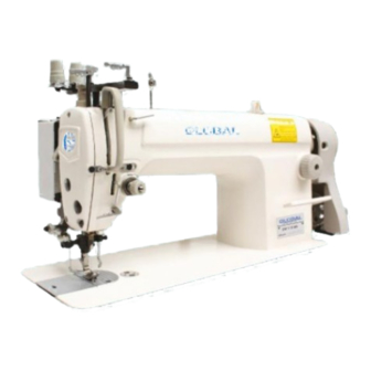
- Page 1 GLOBAL EM 111 Instruction & Parts manual www.globalsew.com info@globalsew.com...
-
Page 3: Table Of Contents
l. PRECAUTIONS BEFORE STARTING OPERATION ............... 1 2. MAIN SPECIFICATIONS ....................1 3. PREPARATION AND LUBRICATION................ 2 4. REPLACE NEEDLES ..... . 5. NEEDLE, THREAD AND MATERIAL TO BE SEWN .............. 3 6. -
Page 6: Preparation And Lubrication
3. PREPARATION AND LUBRICATION 1) Cleaning the machine Before leaving the factory, the machine parts are coated with rust-preventive grease, which may be hardened and contaminated by dust during storage and shipment. This grease must be removed with gasoline. 2) Examination Though eyery machine is confirmed by strict inspection and test before leaving the factory, the machine parts may be loose or deformed after long distance transportation with jolt. -
Page 7: Needle, Thread And Material To Be Sewn
5. NEEDLE, THREAD AND MATERIAL TO BE SEWN 6.THREADING (Fig.3) To thread the needle thread, raise needle bar to the upper end of its stroke, lead the thread from spool arid perform threading as shown in Fig.3. To draw the bobbin thread, hold. the end of the needle thread and turn the balance wheel to lower the needle bar and then to lift it to its highest position. -
Page 8: Set Stitch Length And Reverse Feeding
----------------------------------- -- -- - ----- - .. - ----------------- -- ---- --•· Arter ;1clcqn;l.1::ly no::,: iu11 ing 1 lw 111 ;Jckd. 1 irhtt·11 :;c( _;new ( l 1) 1 1v· ,1vetfi!i !i,1hhn:. l)idi111u1n ;,,11g1I; c.ir· 1hrc;1d wiil fill about 80% of bobbin capacity. This ii:(' can be adjusted by ,1clj1Jsti11g '. -
Page 9: Adjust Thread Tension
12. ADJUST THREAD TENSION (Fig.10, 11) clockwise until spring (C) comes to the notch of thread tension regulating bushing, and again tum tension stud (B) halfway back (counter-clockwise) After the adjustment, tighten set screw (A). 2) Adjusting the thread take-up spring stroke Loosen set screw (B), tm' n stud (C) clockwise to increase the stroke or turn stud (C) counter-clockwise to decrease the stroke. -
Page 10: Time Needle To Rotaing Hook
Thread guide position Leftward Center Rightward Material weight . Heavy Medium Light Fig.12 shows different stitch forms. Normal stitch form should be as shown in Fig.12 (a). When abnormal stitches cause puckering and thread break-age, the tension of needle thread an� bobbin thread must be adjusted accordingly. 1) In case needle thread tension is too strong or bobbin thread tension is too weak, as shown in Fig.12 (b), turn the thumb nut counter-clockwise to decrease the needle thread... -
Page 11: Replace Rotating Hook
(5) After the· adjustment, tighten set screw (B) and put in the rubber plug. The standard needle timing (Fig.15) is to align timing mark (B) on the needle bar and the bottom of needle bar bushing (A) and meanwhile align the inner surface (E) of . the hook and the center of needle eye (D) when the needle bar gets down to its lowest position. -
Page 12: Adjust The Position Of Feed Dog
17. ADJUST 'I'HE POSITION OF 2) Loosen screw (A) of feed lifting rock shaft crank right (See Fig.19, b) 3 ) Move feed bar (B) in the direction shown by the arrow in Fig.19 ( a) to adjust the height of the feed dog. The standard height offeed dog is that the top of feed dog is 0.8nnn above throat plate surface (B). -
Page 13: Adjust Opening Time Of The Tension Discs
· ----····--·· · -· ·--······ . •. ··· · · · ··· · · ·· · -··· · ·····-·----·--- · · · ·· -------- The standard timing of teed motion 10 11f·ecl le 111ot ion is that tlic Lnp of 1red dog (C) is flush with throat plate surface (B) when the point of needle (A) reaches throat plate surracc (8) (Fig.21.) If feed motion is not timed lo ncccllc 11101io11. -
Page 14: Regular Cleaning
21. REGULAR CLEANING (Fig.27) ) ) Cleaning feed dog Remove the throat plate and clear olT the dust and lint between feed dog tooth slots. 2) Cleaning rotating hook Swing out the machine head and clean the hook. Wipe the bobbin case with soft cloth. Feed dog 3) Cleaning oil pump, screen Swing out the machine head and clear off the dust... - Page 16 1. ARM BED AND ITS ACCESSORIES - 14 -...
- Page 17 1. ARM BED AND ITS ACCESSORIES 11H1-001A1 Machine head 11H1-001A2 Bedplate 11 H1-001 B2 Trademark plate GB827-86 Rivet 54T1-005 Face plate 54T1-00282 Gasket 72T1-004C3 Rubber plug 0 19 72T1-004C4 Rubber plug 0 11 ,8 74T1-004C1 Thread guide 22T1-006C6 Thread guide screw 72T1-016 Screw 22T1-005D1...
- Page 18 ©- ® 2. _ S EWING MECHANISM @--1 -16 -...
- Page 19 2. SEWING MECHANISM 11H2-001A1a1 Thread take-up lever 11 H2-001A1 b1 Thread take-up lever link 22T2-001A3 Hinge pin 73T2-001A1 Thread take-up crank 22T2-001A5 Needle bearing 22T2-001A6 Screw 22T2-001A3 Needle bar link Needle bar adaptor 22T2-001A8 22T2-001A9 Set screw Set screw 22T2-002 74T2-002 Thread take-up guard 72T2-003...
- Page 20 -18- 3. SEWING MECHANISM - - -...
- Page 21 3. SEWING MECHANISM 72T3-001A1 Arm shaft 22T3-001A2 Plug 0 7,4 x 10 22T6-005B1 Collar 22T3-002B2 Set screws 22T3-003 Arm shaft bushing (left) 22T3-004 Arm shaft bushing (middle) 22T2-002 Set screws 22T3-005 Arm shaft bushing (right) 22T3-006F Oil seal 11 H3-001A1 Handwheel 22T3-007C2 Set screws...
- Page 23 4. ROTATING HOOK MECHANISM 74T-001A1 Rotating hook shaft 22T4-001A1 a1 Filter screw 72T4-001A1 a2 Filter 72T4-002B1 Collar 72T4-002B2 Set screw 22T4-003G Oil seal 22T4-004 Hook shaft bushing (left) 72T4-003 Oil adjusting screw 22T4-006 Spring 72T4-008C1 Hook shaft bushing (right) 22T4-007C2 Set screw 72T4-010 Plunger...
- Page 24 21 - REGULATOR :>. � MECHANISM 111 l,;H...
- Page 25 5. STITCH REGULATOR MECHANISM Hinge pin 22T5-001A1 Feed connecting link 22T5-001A2 Hinge pin 22T5-001A3 22T5-001A4 Set screw 72T5-00281 Feed regulator 22T5-001 D4 Set screw 72T5-002 Feed regulator bushing 22T5-002 Sew screw 22T5-004 Hinge pin 72T5-003 Rubber plug 73T5-003C1 Feed regulator screw 22T5-006C4 O-ring 11 H5-001A1...
- Page 26 6. FEEDING, FEED LIFTING & LOWER SHAFT MECHANISM ---- � • � - - � ® -23-...
- Page 27 6. FEEDING, FEED LIFTING & LOWER SHAFT MECHANISM 72T6-001A1 Feed bar crank 72T6-001A6 Screw 20H11-001 B1 Feed bar 22T6-001A3 Feed dog 22T6-001A4 Screw 11 H6-004 Shaft for feed bar 22T2-019 Screw 11 H6-007 Bushing 72T6-001A5 Oil wick 11 H6-006 Bushing 2T5-001A4 Screw 11 H6-001...
- Page 28 7. PRESSER FOOT MECHANISM ® ---- ® -----@ �'"""' =-'A----- � • ®� ��- - - -® ....® f-------@ - 25 -...
- Page 29 7. PRESSER FOOT MECHANISM 72T7-010F1 Presser bar lifter 22T1-011 Set screw 72T7-001A1 Presser bar lifter cam 72T7-008 O-ring 22T7-004B 1 a Knee lifter lever (left) 72T7-002B1-1 Tension release cam 22T7-004B 1 c Screw 22T7-004B2 Screw 22T7-004B3 Knee lifter rod Screw 22T7-005 Tension release pin 22T7-006...
- Page 31 8. OIL LUBRICATION MECHANISM 22T8-001 Oil pump body 22T8-002 Oil pump impeller 22T8-003 Screw 72T8-005 Screw 22T8-005 Spring washer 22T8-006 Oil pump fitting plate 22T8-007 Oil adjusting plate 22T8-008A Oil pump screen complete 22T8-009 Screw 22T8-010B Oil pipe for hook shaft 72T8-001A Oil braid fitting plate 22T7-015...
- Page 33 9. OIL RESERVOIR AND BEL TGUARD 74T9-001A1 Oil reservoir 22T9-001A2 Oil drain screw Washer 22T9-001A3 Gasket (big) 22T9-001A4 Gasket (small) 22T9-001A5 Hinge pin for kneelifter 72T9-016 22T9-001A7 Spring 22T9-001A8 Kneelifter stop bracket 22T9-001A9 Adjusting screw 22T9-001 A 1 0 Lock nut 22T9-003B1 Knee lifter lifting rod 22T9-003B2...
- Page 34 1 0 . __ A C C E S S U K II:. :) -------®...
- Page 35 10. ACCESSORIES 22T9-007F1 Hinge of machine head 72T9-004C1 Machine rubber 73T2-004 Needle (DJx1) 72T9-005 Rubber cushion (big) 72T9-006 Rubber cushion (small) 22T9-011 Oiler 22T9-012 Magnet 72T9-007 Screw driver (long) 72T9-020 Screw driver (medium) 72T9-021 Screw driver (short) 72T9-022 Wrench 22T9-017 Oil container 11 H4-001 Bobbin...
Need help?
Do you have a question about the EM 111 and is the answer not in the manual?
Questions and answers