Piusi K24 Installation, Use & Maintenance Manual
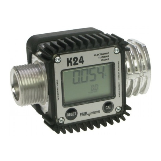
Electronic turbine meter
Hide thumbs
Also See for K24:
- Use, maintenance and installation manual (2 pages) ,
- Use and maintenance manual (2 pages) ,
- Calibration manual (1 page)

Related Manuals for Piusi K24


Summary of Contents for Piusi K24
- Page 1 ELECTRONIC TURBINE METER Use, maintenance and calibration manual Bulletin M0171G EN_...
-
Page 2: Table Of Contents
FACSIMILE COPY OF EU DECLARATION OF CONFORMITY GENERAL WARNINGS SAFETY INSTRUCTIONS SAFETY WARNINGS FIRST AID RULES GENERAL SAFETY RULES PACKAGING PACKAGE CONTENTS/PRE-INSPECTION BECOMING ACQUAINTED WITH K24 COMPATILE LIQUIDS DISPLAY LCD DISPLAY POSITIONING (METER VERSION ONLY) USERS BUTTONS OPERATING MODES INSTALLATION PULSER INSTALLATION DIAGRAM... -
Page 3: Facsimile Copy Of Eu Declaration Of Conformity
- Electromagnetic compatibility The technical file is at the disposal of the competent authority following motivated request at PIUSI S.p.A. or following request sent to the e-mail address: doc_tec@piusi.com. THE ORIGINAL DECLARATION OF CONFORMITY IS PROVIDED SEPARATELY WITH THE PRODUCT... -
Page 4: Safety Instructions
Use, maintenance and calibration SAFETY INSTRUCTIONS SAFETY WARNINGS Mains - preliminary ATTENTION checks before You must avoid any contact between the electrical power supply and the installation fluid that needs to be FILTERED. Maintenance Before any checks or maintenance work are carried out, disconnect the power source. -
Page 5: First Aid Rules
1 - contents of the package 2 - weight of the contents 3 - description of the product 5/124 5 /20 This manual is the property of PIUSI S.p.A. Any reproduction, even partial, is forbidden. -
Page 6: Package Contents/Pre-Inspection
60 l/min COMPATIBLE LIQUIDS Turbine The turbine is placed inside a hole through the body of k24, fitted with M-M threaded inlet and outlet. The supplied F-F bushing enables several combinations of threads. K24 HAS 2 measurement RUBBER PROTECTIONS, DESIGNED TO ACT AS GASKETS TOO. -
Page 7: Display Lcd
DISPLAY POSITIONING (METER VERSION ONLY) FOREWORD The square shape of the k24 body allows the card to be rotated in its housing, thus ensur- ing great versatility in positioning This allows easy display readings in any position. The card housing is closed by a plastic cover sealed through a rubber protection acting as a gasket as well. -
Page 8: Users Buttons
MODES event of a complete power break for long periods. The measurement electronics and the LCD display are fitted in the top part of the K24 standard counter of customers which remains isolated from the fluid-bath measurement chamber and sealed from the outside by means of a cover. -
Page 9: Meter Installation
METER INSTALLATION FOREWORD K24 features a threaded, perpendicular inlet and outlet (1” BSP male and female that can be combined together). It has been designed to be easily installed in any position: fixed in-line or mobile on a dispensing nozzle. In order to improve the life of the turbine, it is rec-... -
Page 10: Partial Reset (Normal Mode)
Use, maintenance and calibration 7.1.1 PARTIAL RESET (NORMAL MODE) The partial register can be reset by pressing the reset key when the meter is in standby, meaning when the display screen shows the word “TOTAL”. After pressing the reset key, during reset, the display screen first of all shows all the lit-up digits and then all the digits that are not lit up. -
Page 11: Dispensing With Flow Rate Mode Display
RESET CALIBRATION When operating close to extreme use or flow rate conditions (close to minimum or maximum acceptable values), an on-the-spot calibration may be required to suit the real conditions in which the K24 is required to operate. DEFINITIONS CALIBRATION Multiplication factor applied by the system to the electrical pulses received, to transform these into measured fluid units. -
Page 12: Calibration Mode
In calibration mode, the partial and total dispensed quantities indicated on the display screen take on differ- ent meanings according to the calibration procedure phase. In calibration mode, the K24 cannot be used for normal dispensing operations. In “Calibration” mode, the totals are not increased... -
Page 13: Display Of Current Calibration Factor And Restoring Factory Factor
ATTENTION When the Factory Factor is confirmed, the old User factor is deleted from the memory 13/124 13 /20 This manual is the property of PIUSI S.p.A. Any reproduction, even partial, is forbidden. -
Page 14: 8.2.2 In Field Calibration
This procedure calls for the fluid to be dispensed into a graduated sample container in real operating conditions ( flow rate, viscosity, etc.) requiring maximum precision. ATTENTION For correct K24 calibration, it is most important to: 1 When the Factory Factor is confirmed, the old User factor is deleted from the memory 2 use a precise Sample Container with a capacity of not less than 5 litres, featuring an accurate graduated indicator. - Page 15 The Meter stores the new work calibration factor and is ready to begin dispensing, using the USER K FACTOR that has just been calculated.. 15/124 15 /20 This manual is the property of PIUSI S.p.A. Any reproduction, even partial, is forbidden.
-
Page 16: 8.2.3 Direct Modification Of K Factor
Use, maintenance and calibration 8.2.3 DIRECT MODIFICATION OF K FACTOR If normal Meter operation shows a mean percentage error, this can be corrected by applying to the cur- rently used calibration factor a correction of the same percentage. In this case, the percentage correction of the USER K FACTOR must be calculated by the operator in the following way New Cal. -
Page 17: Meter Configuration
The Reset Total and Total registers will be automatically changed to the new unit of measurement. NO new calibration is required after changing the Unit of Measurement. 17/124 17 /20 This manual is the property of PIUSI S.p.A. Any reproduction, even partial, is forbidden. -
Page 18: Maintenance
K24 will switch on automatically and normal operation can be resumed follows The K24 will display the same Reset Total, the same Total and the same Partial indicated before the batteries were changed. After changing the batteries, the meter does not need calibrating again. -
Page 19: Malfunctions
Other components, such as pipes, rubber gaskets, plastic parts and wires, must be dis- posed of by companies specialising in the disposal of industrial waste. parts disposal 19/124 19 /20 This manual is the property of PIUSI S.p.A. Any reproduction, even partial, is forbidden. - Page 20 TURBINE Resolution Hi Flow 0.010 lit/pulse Low Flow 0.005 lit/pulse (nominal) Flow Rate K24 COL. BLACK 5 ÷ 120 (Litres/minute) FOR DIESEL FUEL, WATER,. (Range) K24 COL. BEIGE 5 ÷ 100 (Litres/minute) FOR WATER/UREA SOLUTION.. Operating pressure (Max) 10 (Bar) 145 (psi)
-
Page 21: Exploded Views And Overall Dimensions
EXPLODED VIEWS AND OVERALL DIMENSIONS METER PULSER 21/124 21 /20 This manual is the property of PIUSI S.p.A. Any reproduction, even partial, is forbidden. - Page 22 Use, maintenance and calibration 22 /20 M0171G...
- Page 24 ¡Descarga el manual en tu idioma! Lataa käsikirja omalla kielelläsi! Téléchargez le manuel dans votre langue! Download de handleiding in uw taal! Pobierz instrukcję w swoim języku! Baixe o manual em seu idioma! Загрузите руководство на вашем языке https://www.piusi.com/ support/search-manuals Bulletin M0171G EN_ 03.2024...
Need help?
Do you have a question about the K24 and is the answer not in the manual?
Questions and answers